?
DIY ExpressLRS TX Nano module
Remarks
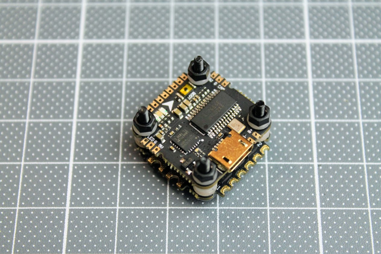
DIY Nano TX module build uses modular design it means it uses pre build modules. Only a few additional components are used (one resistor and one capacitor). Almost anyone could build this TX module with little soldering experience.?
Nano sized DIY TX module can be installed in the full and nano size JR module case. It can be even installed inside the radio as it is really small.
TX Parts list
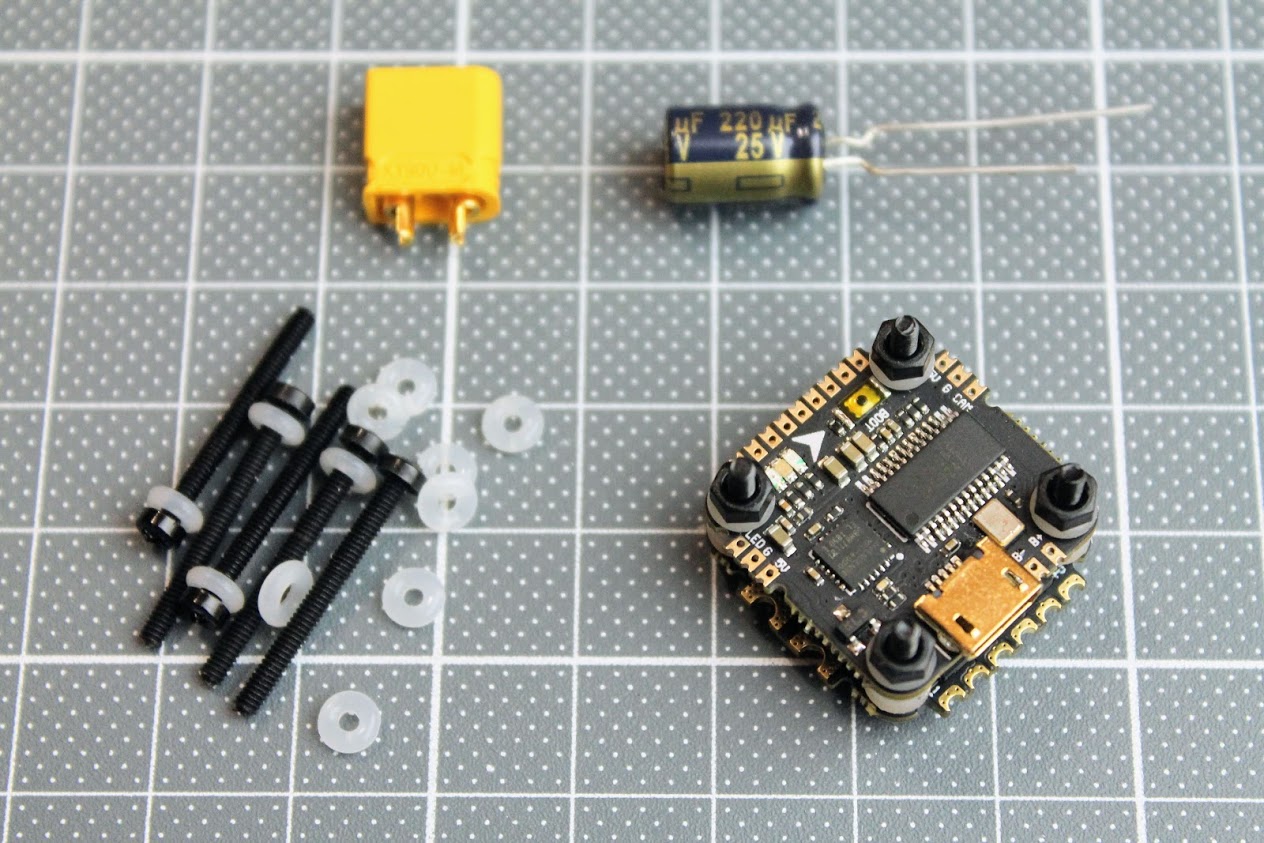
Parts list starts from PCB. I have ordered the PCB on OSH Park?(https://oshpark.com/shared_projects/K4feONmv).?The cost of PCB was $7.10?for?3pcs.
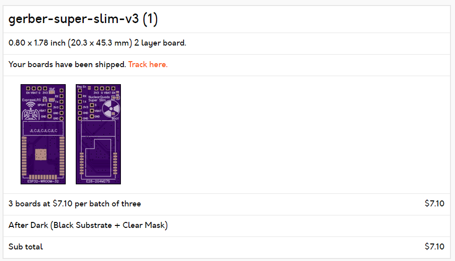
The original gerber files for PCB manufacturing can be found here:?
https://github.com/ExpressLRS/ExpressLRS-Hardware/tree/master/PCB/2400MHz/TX_SX1280_Super_Slim
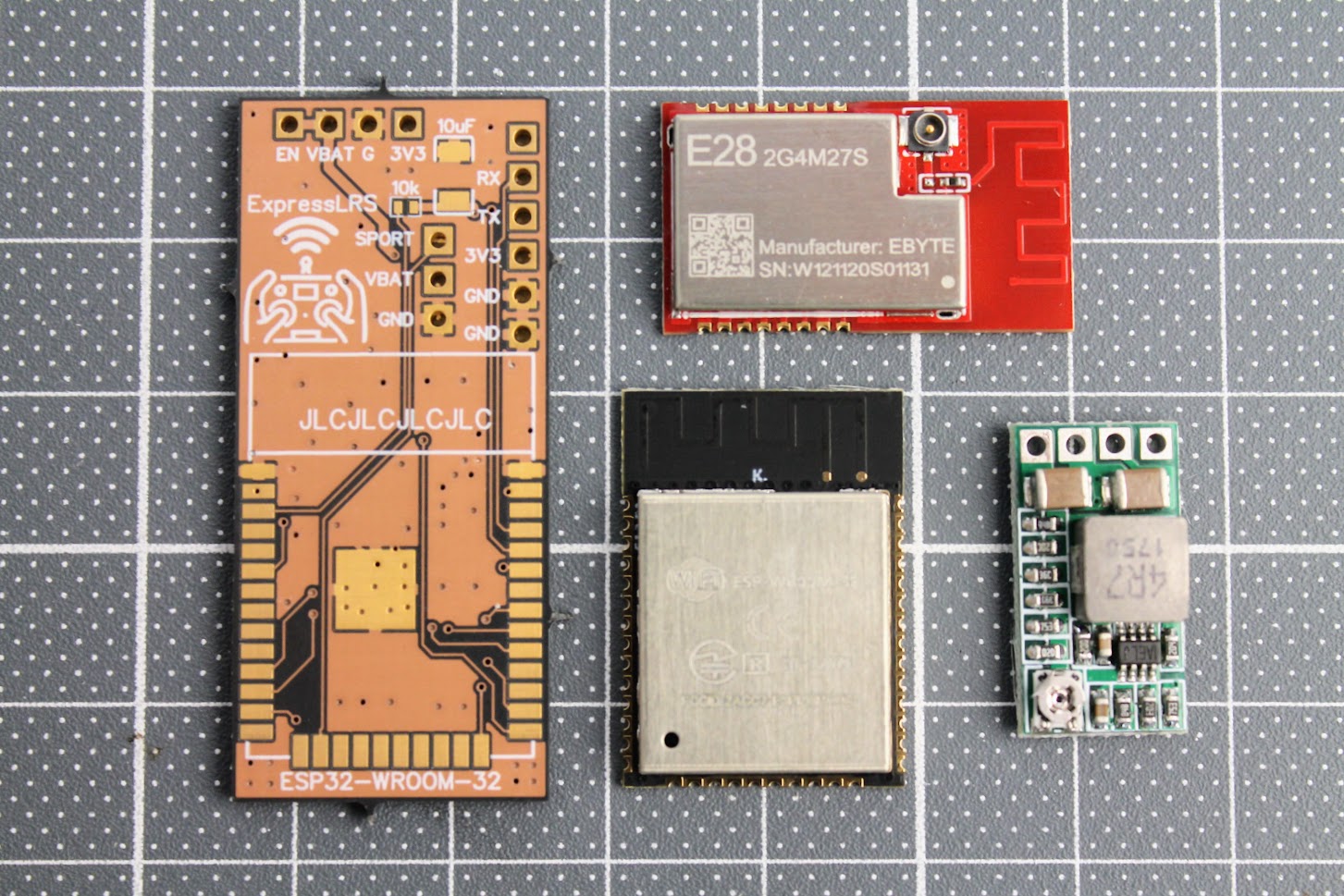
I have purchased all the electronic parts from Aliexpress as it was the cheapest source.
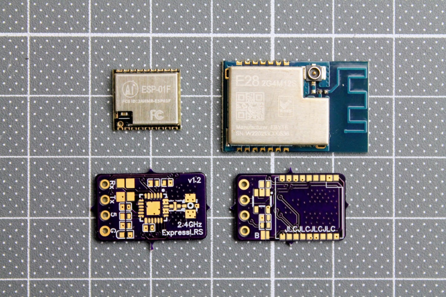
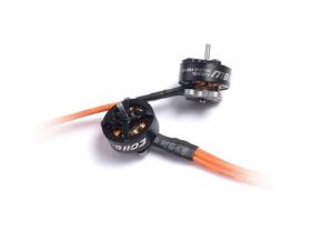
E28-2GM27S LoRa module (~$14) –?https://www.aliexpress.com/item/1005001812234542.html
ESP-WROOM-32? module (~$5) –?https://www.aliexpress.com/item/1005001833545594.html
DC-DC power supply?module (~$2.5) – https://www.aliexpress.com/item/32880983608.html
SMA antenna pigtail (~ $0.5/pcs) –?https://www.aliexpress.com/item/4000848776660.html
Also you will need 10uF SMD capacitor (3528 or type B size) and the 10k?SMD resistor (0402 size).
Other things you will need: 5 pin 2.54mm header socket, silicone wires and of course a soldering iron set.
Build process
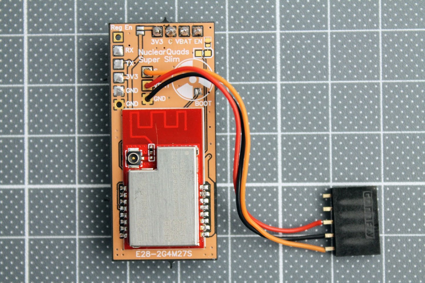
Soldered the ESP32-WROOM module and 10k resistor and 10uF capacitor. Soldering the resistor is the trickiest part as resistor is tiny (0402 size).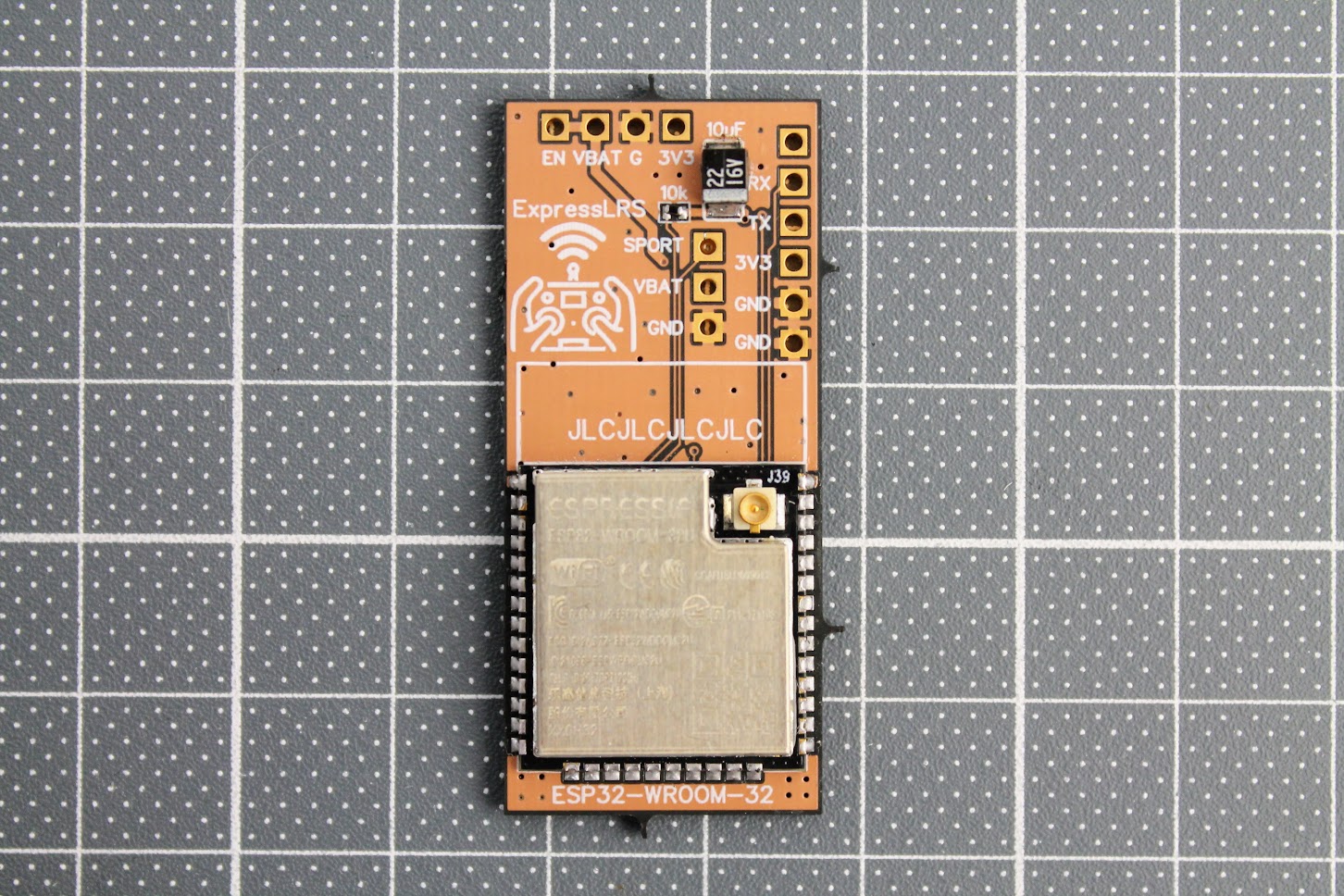
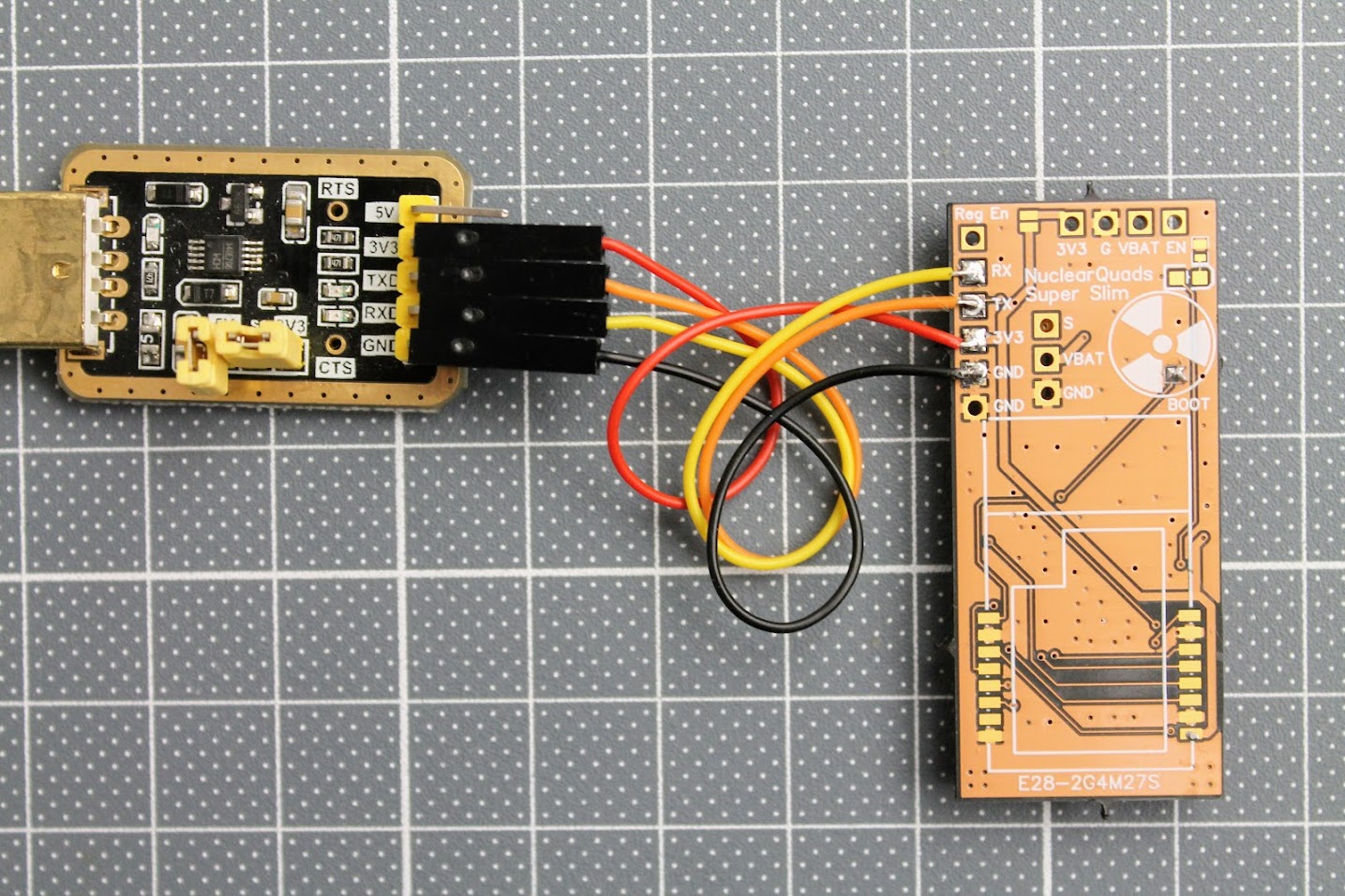
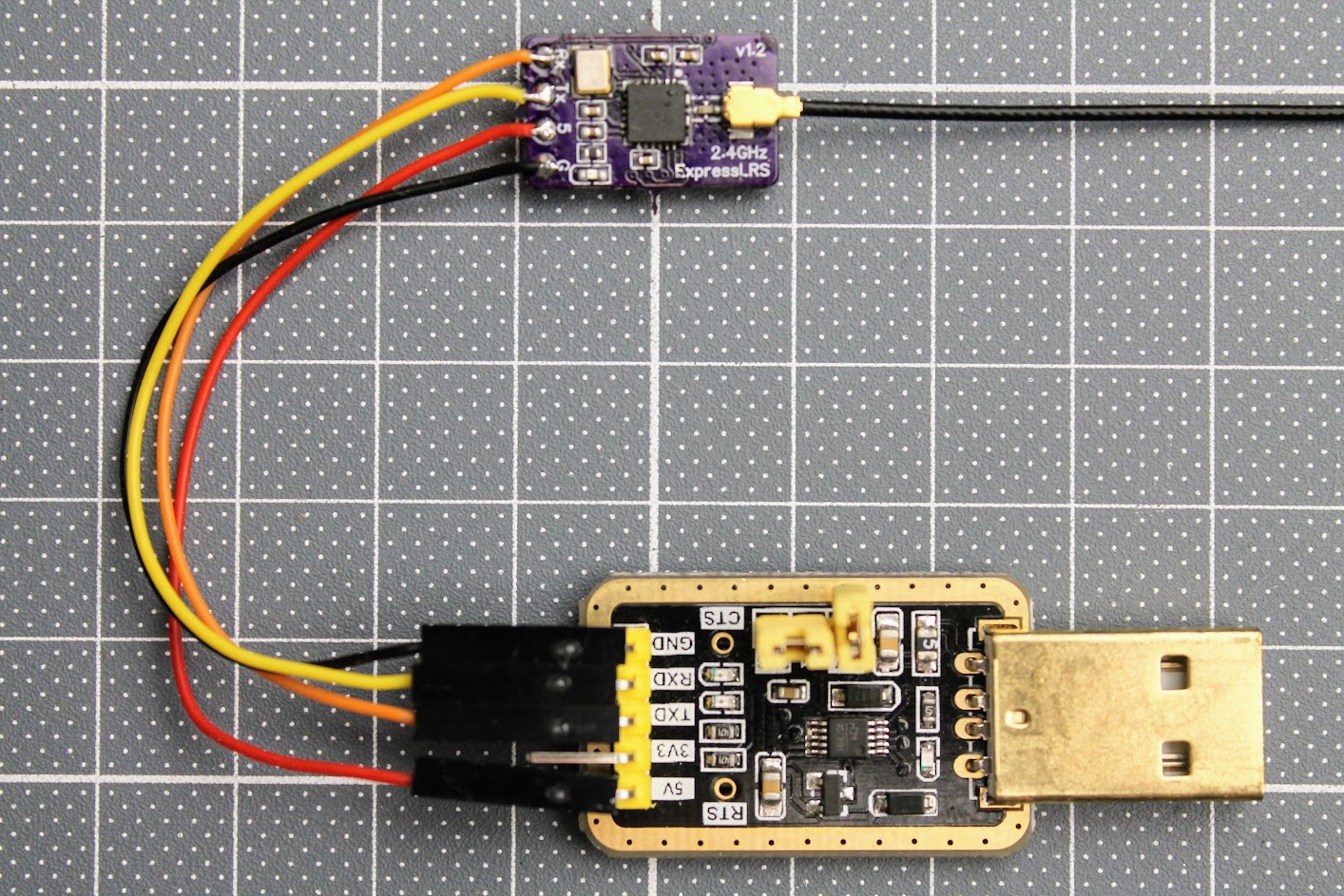
After the ESP32 module is soldered, you need to tempararily solder the RX, TX, 3.3V and GND wires. Connect these wires to the corresponding pins on the FTDI or any other USB to serial adapter. You can even use Arduino board. Don’t forget to short the BOOT pads for flashing the firmware by UART.
At this stage I would recommend to flash the ExpressLRS firmware to the ESP32-WROOM-32 module. For
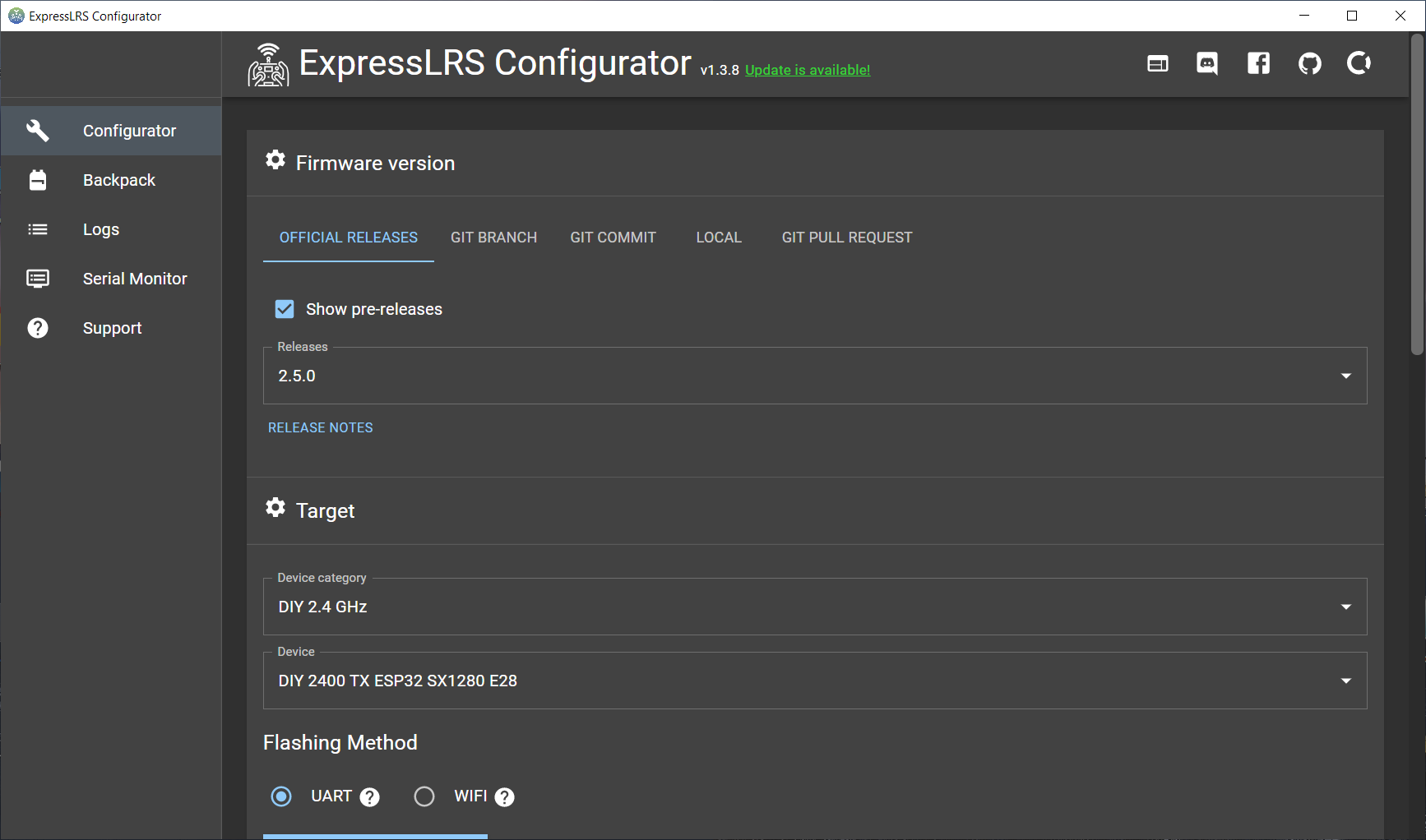
Start the ExpressLRS Configurator. You can download it from here:?https://github.com/ExpressLRS/ExpressLRS-Configurator/releases/?
Select “DIY 2.4 GHz” as Device category and “DIY 2400 TX ESP32 SX12800 E28” as Device.
Select UART as Flashing Method.
Read more about the flashing the ExpressLRS here:
ExpressLRS Open Source Long Range radio control system – Complete Guide
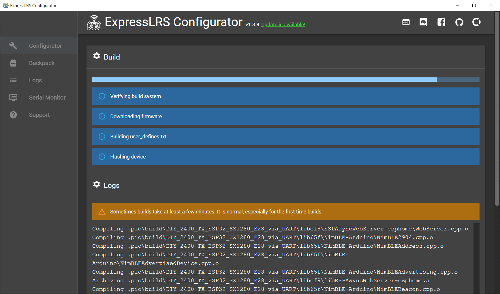
Press [Build & Flash]. Wait several minutes for it to compile.
And flashing successful!
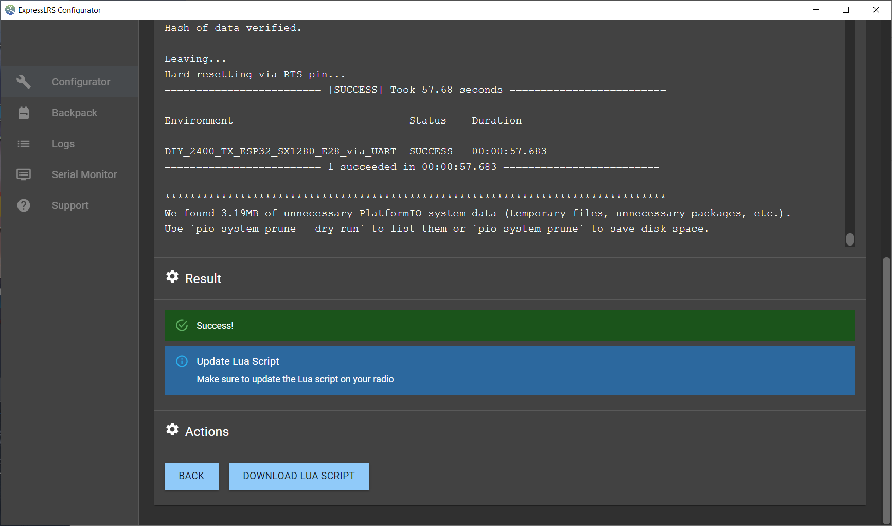
Now you can unsolder the FTDI (USB to Serial) adapter.
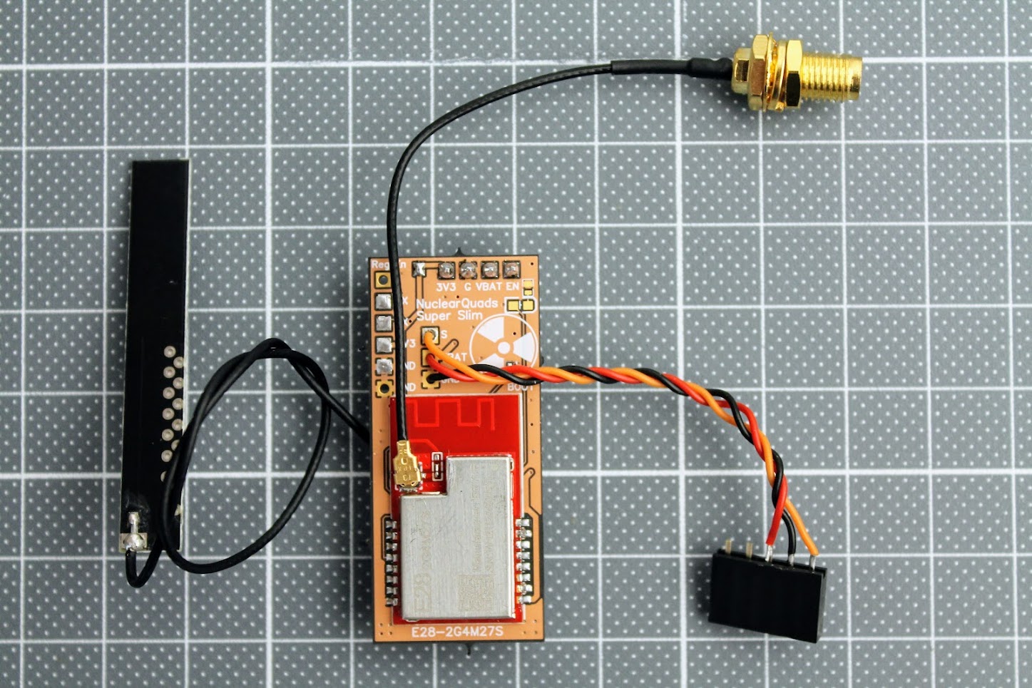
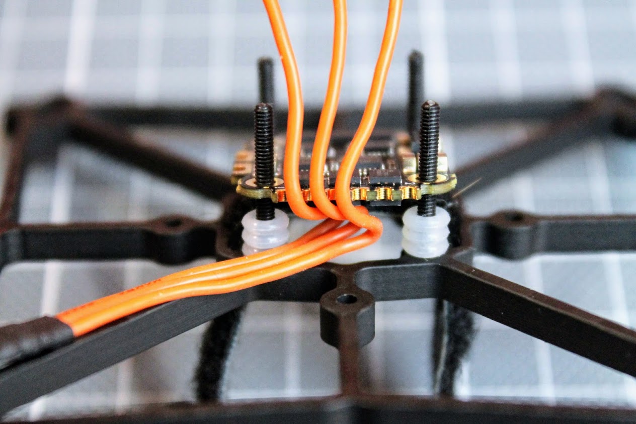
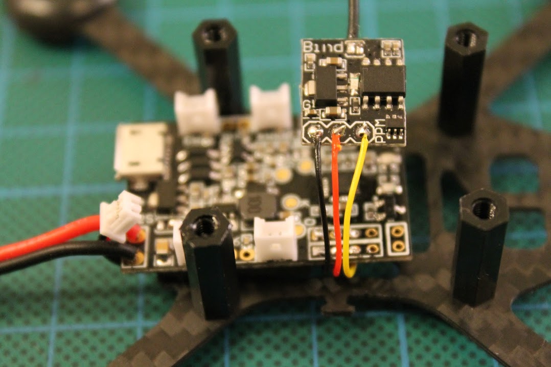
Next step solder the JR bay connector.
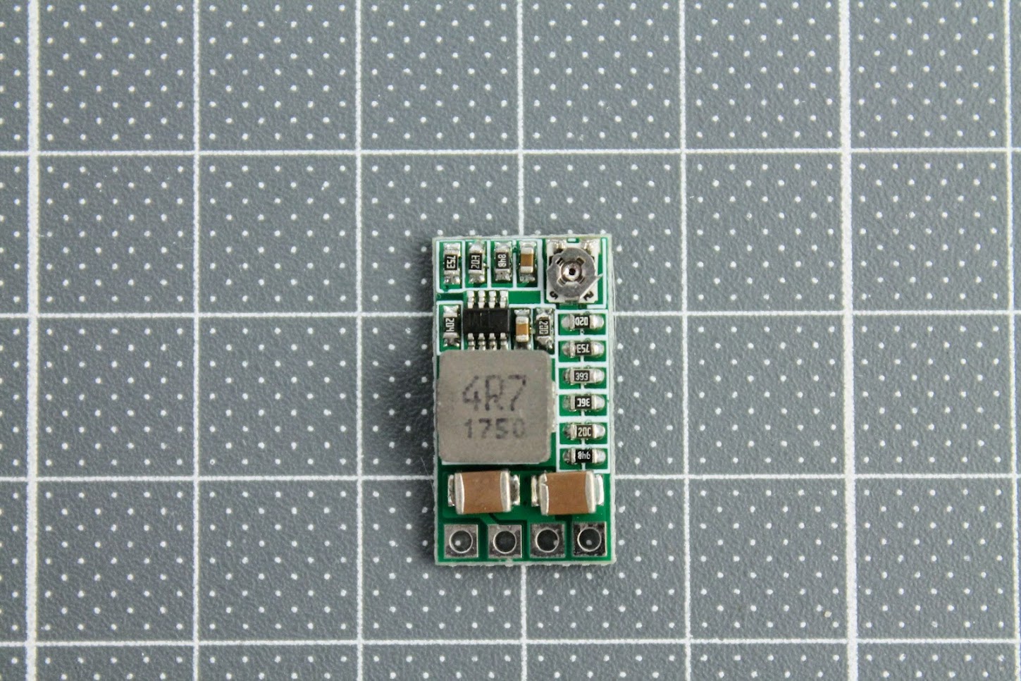
Prepare the power (voltage regulator) module. Short the 5V and 12V pads on the back side of the DC-DC regulator module. This will set the regulator to output the 3.45V, which is slightly more than 3.3V, but within the 5% tolerance of the modules.?
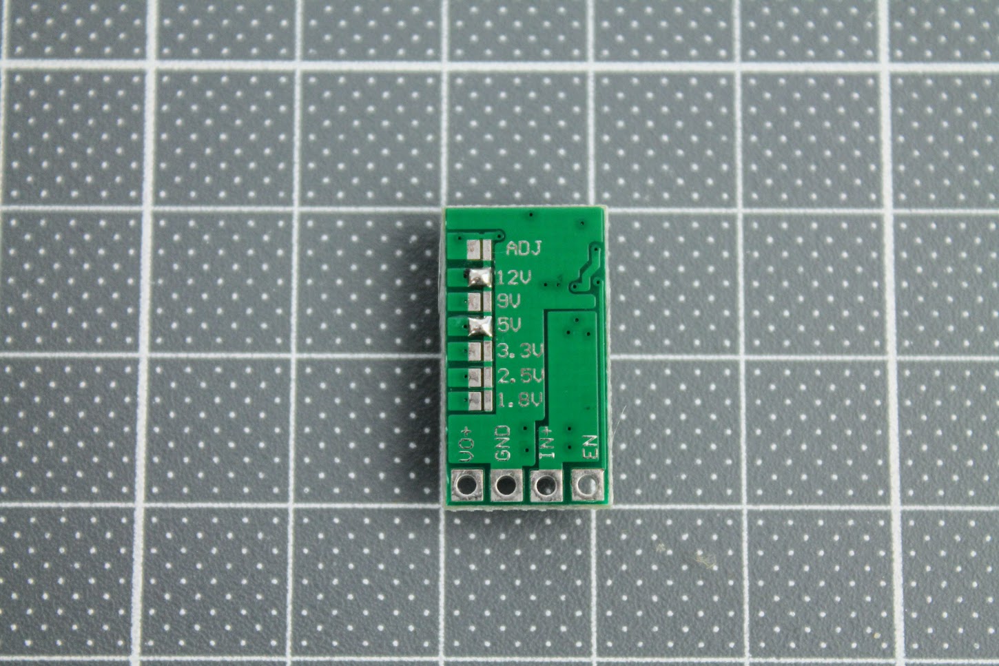
Turn the variable resistor to the clockwise end position (more about it below).
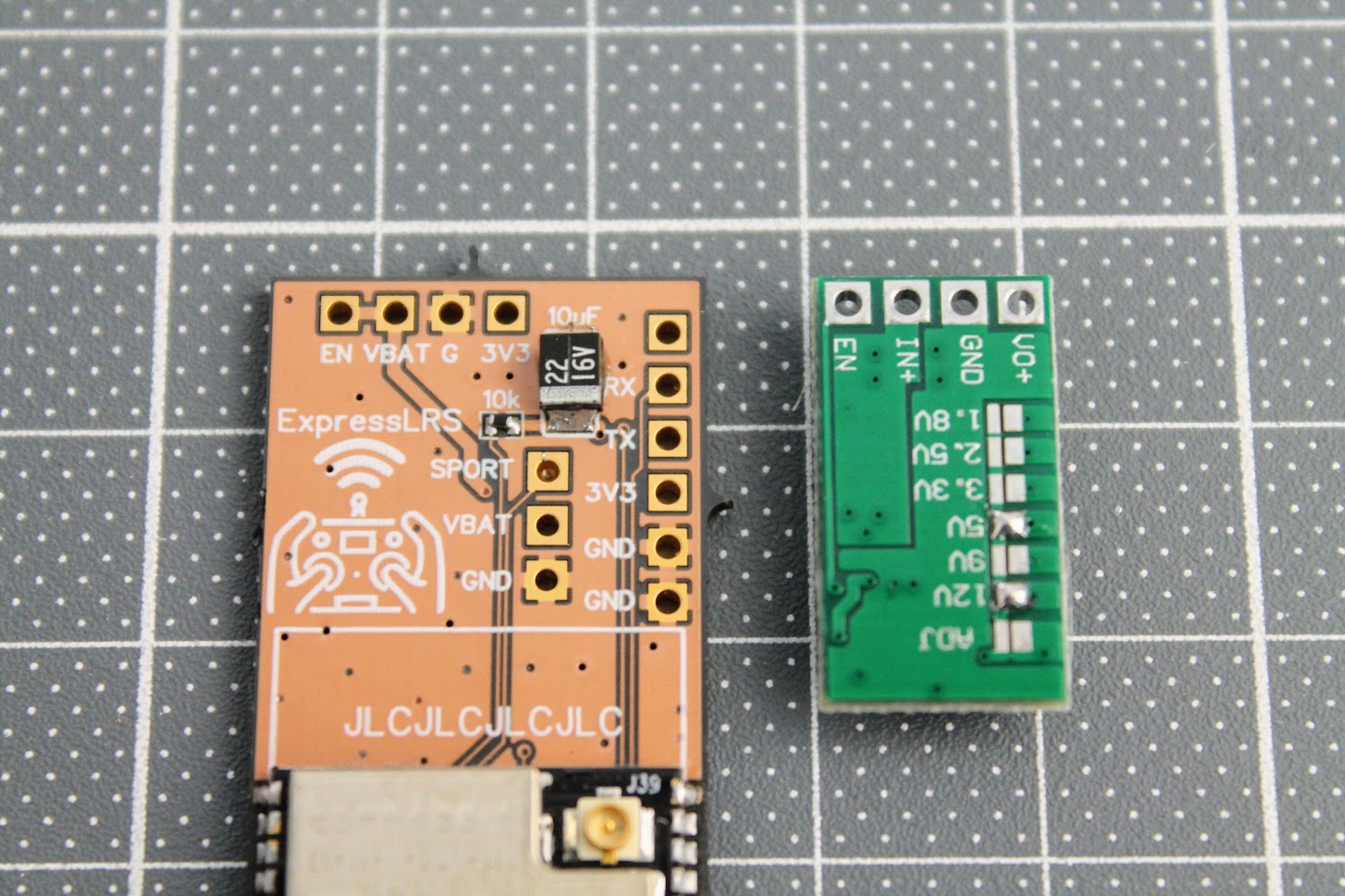
And solder the module to the EN, VBAT, G and 3V3 with the help of the pin headers.
I also would like to suggest to connect the ExpressLRS module to the JR bay, power the radio, enable the External module in the model setup and measure the voltage between the GND and VO+ pads. It should be slightly more than 3.3V, the recommended voltage is 3.45V. In my case I have measured the voltage 3.58V, which is in the range of the absolute maximum voltage ratings (+10%) for the ESP32 and E28 modules, but its not recommended to operate the modules at this voltage, so I have turned slightly the dial on the variable resistor to set the 3.45V, which is 5% more than standard power voltage for modules. In theory E28 module should be happy to have a slight voltage overhead.
I need to notice, that at this point the ESP32 and E28 modules are not powered as the Reg En jumper pads are not connected.
Once the power voltage is set and verified, you can short the?Reg En solder pads and solder the E28-2GM27S module.
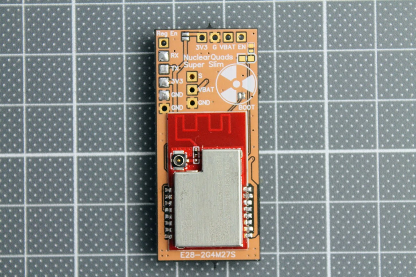
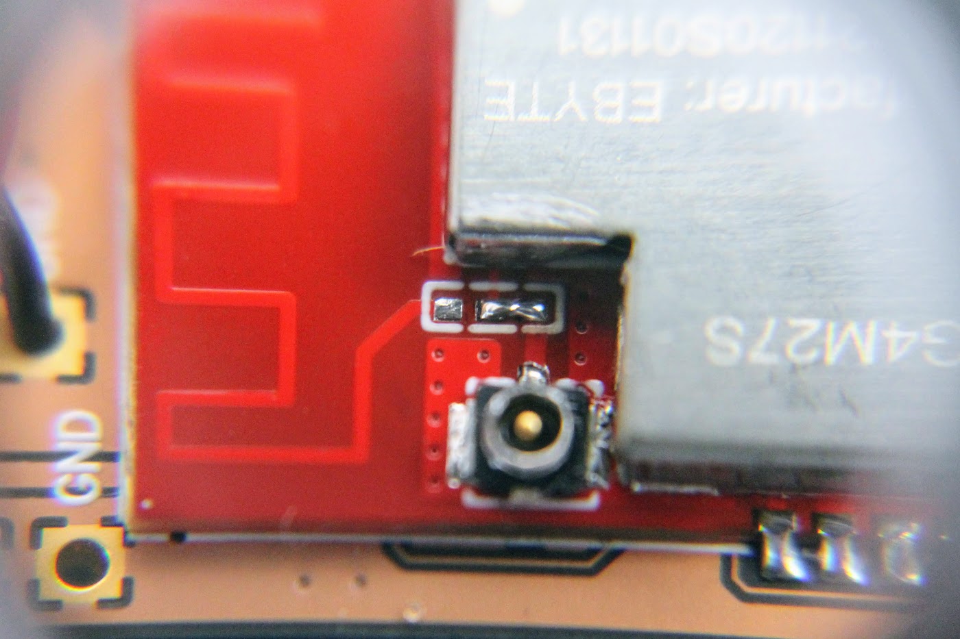
Another tricky part is to switch the zero Ohm resistor from the PCB antenna to the external (ipex) antenna position. I ended up just making the solder blob between the two pads as the resistor is zero ohms anyway.
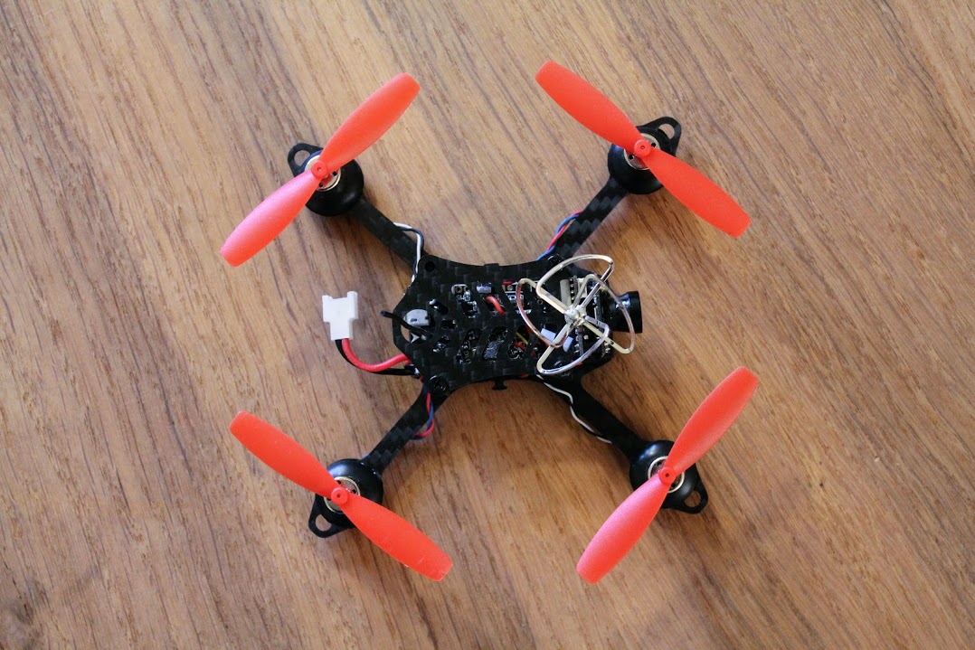
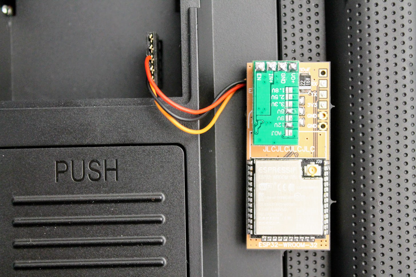
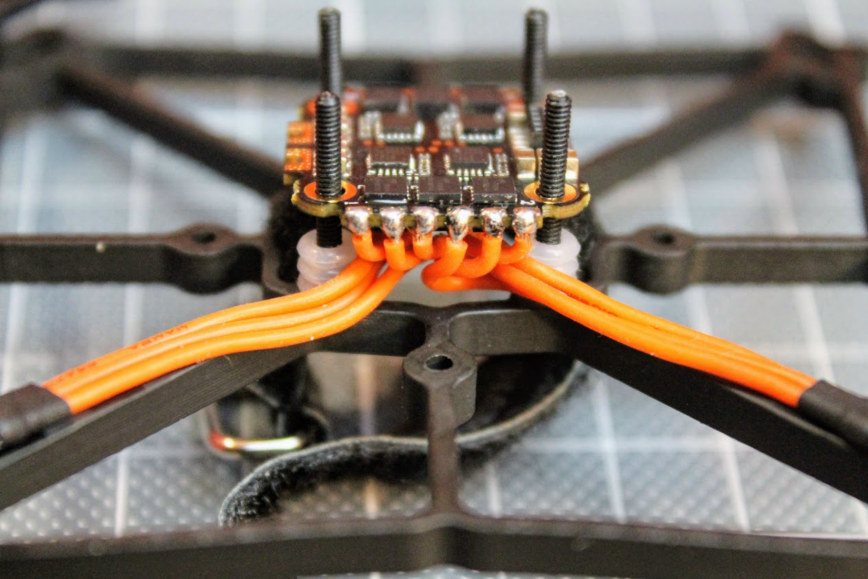
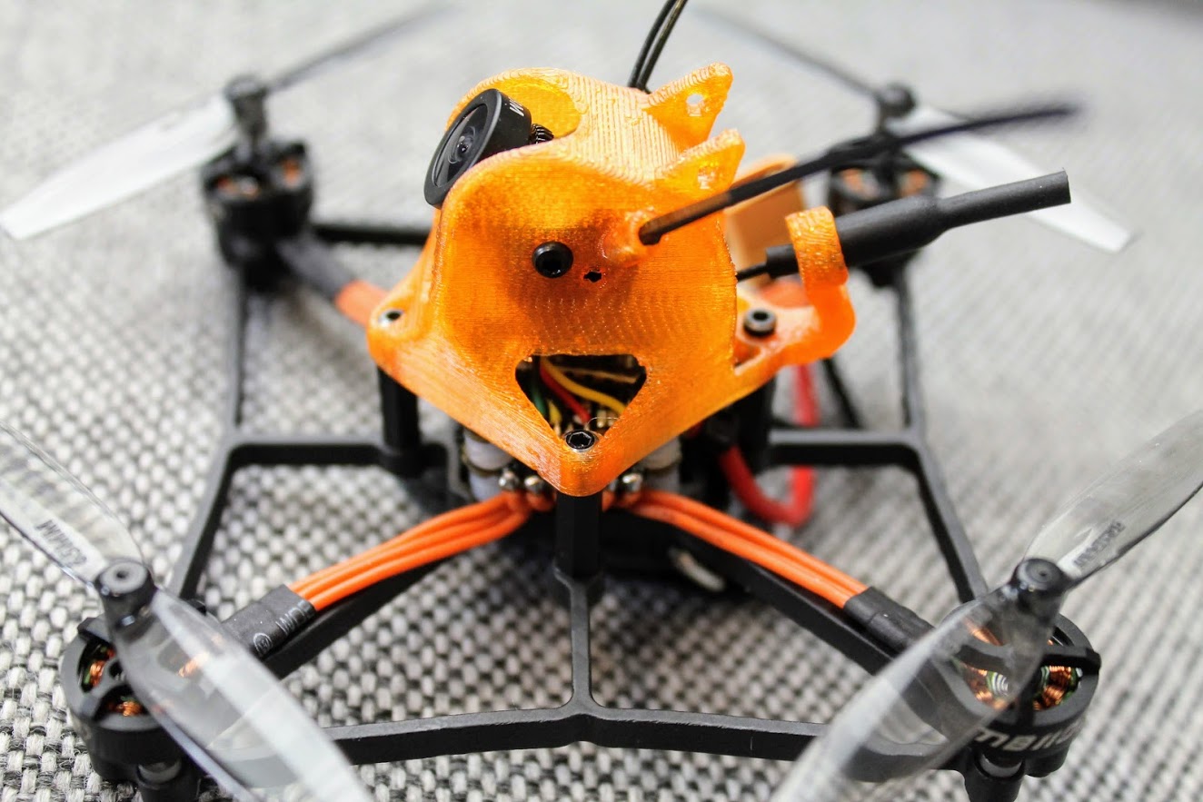
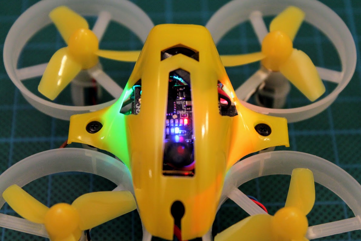
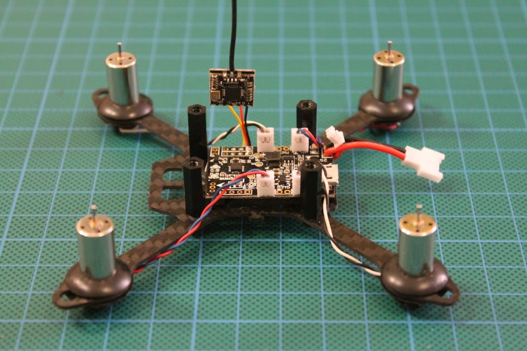
Completely assembled with all the antennas connected. Notice that 3.3V?power line Reg En jumper pads are soldered near the top right corner of the PCB board.
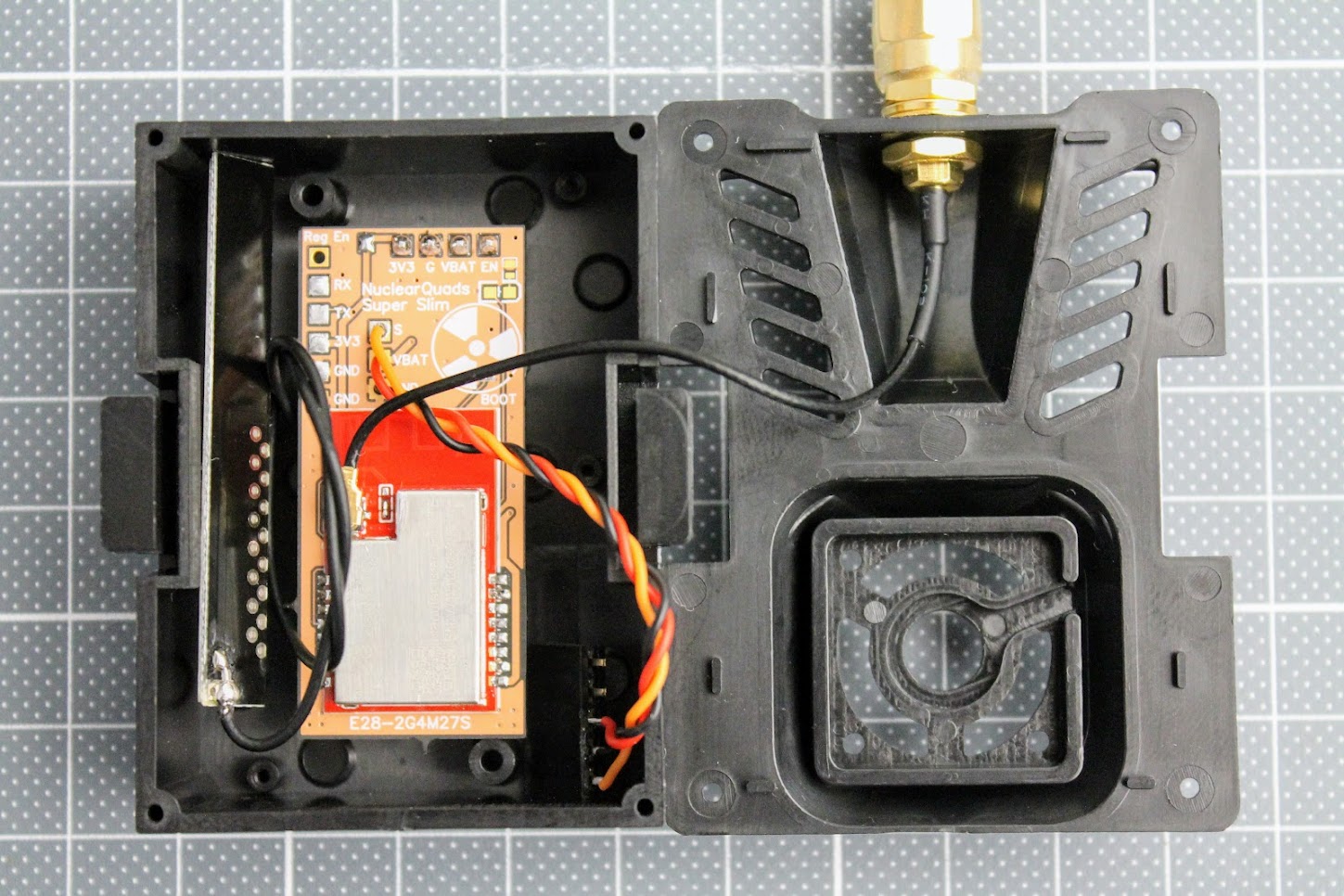
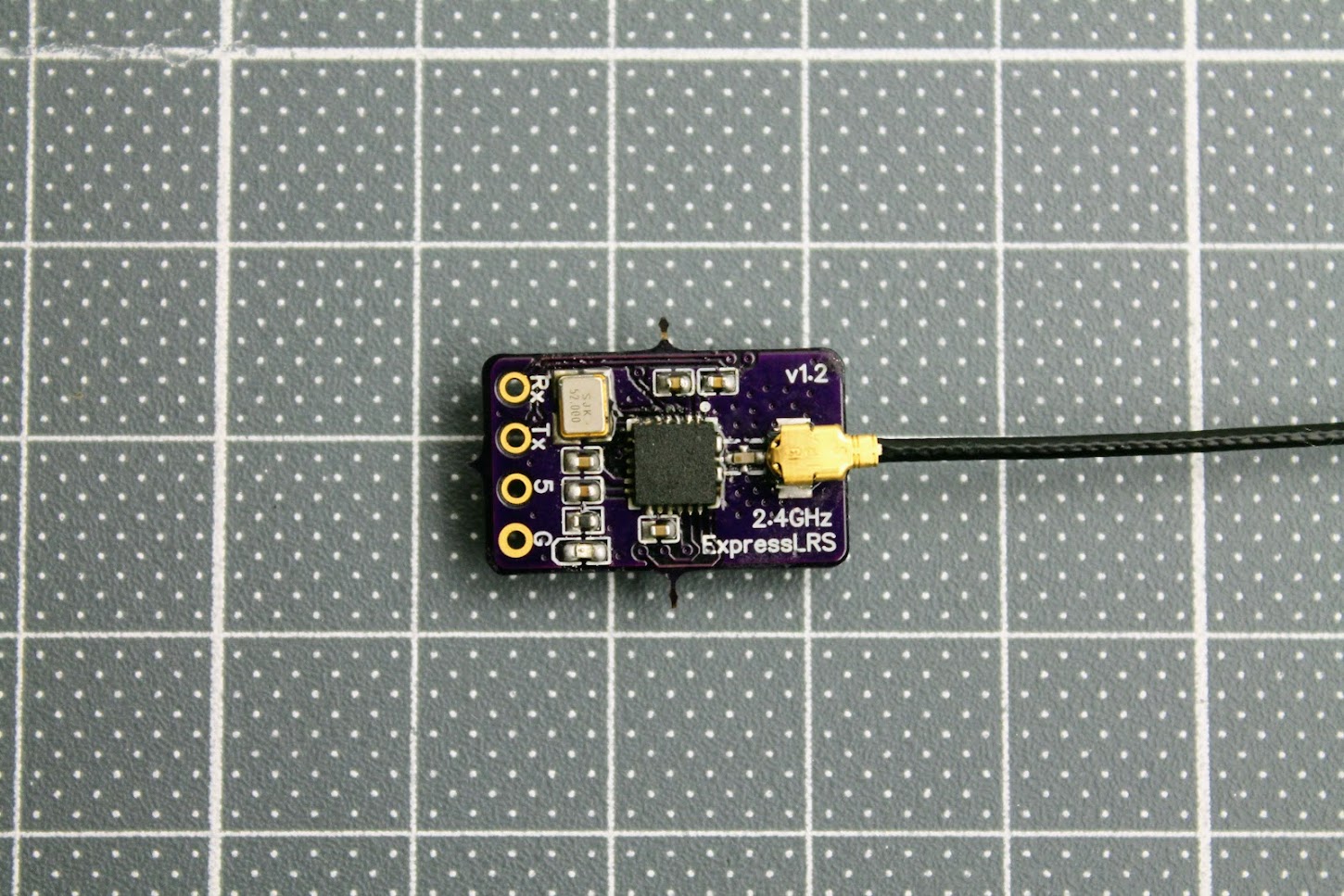
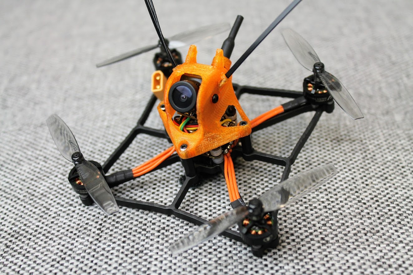
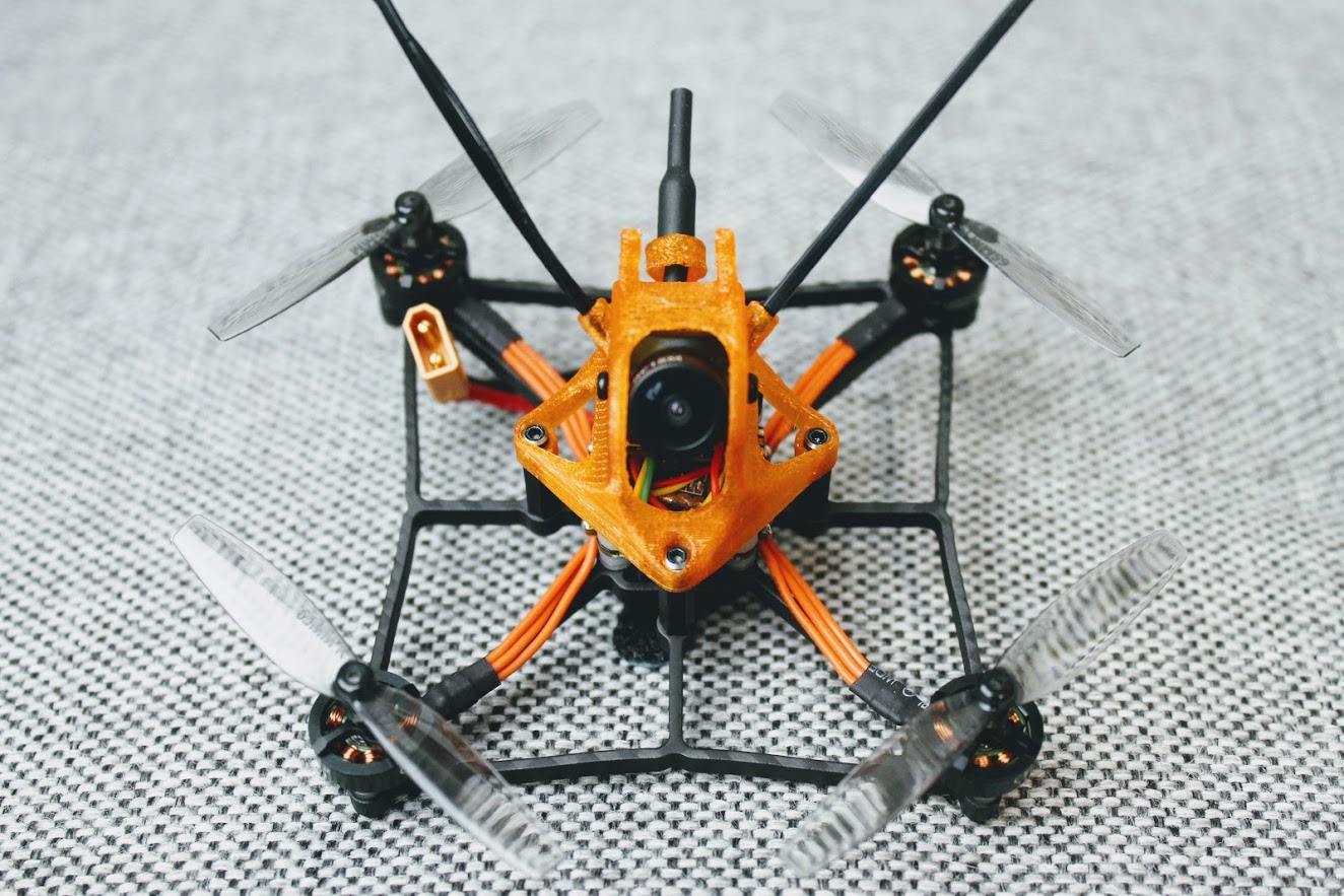
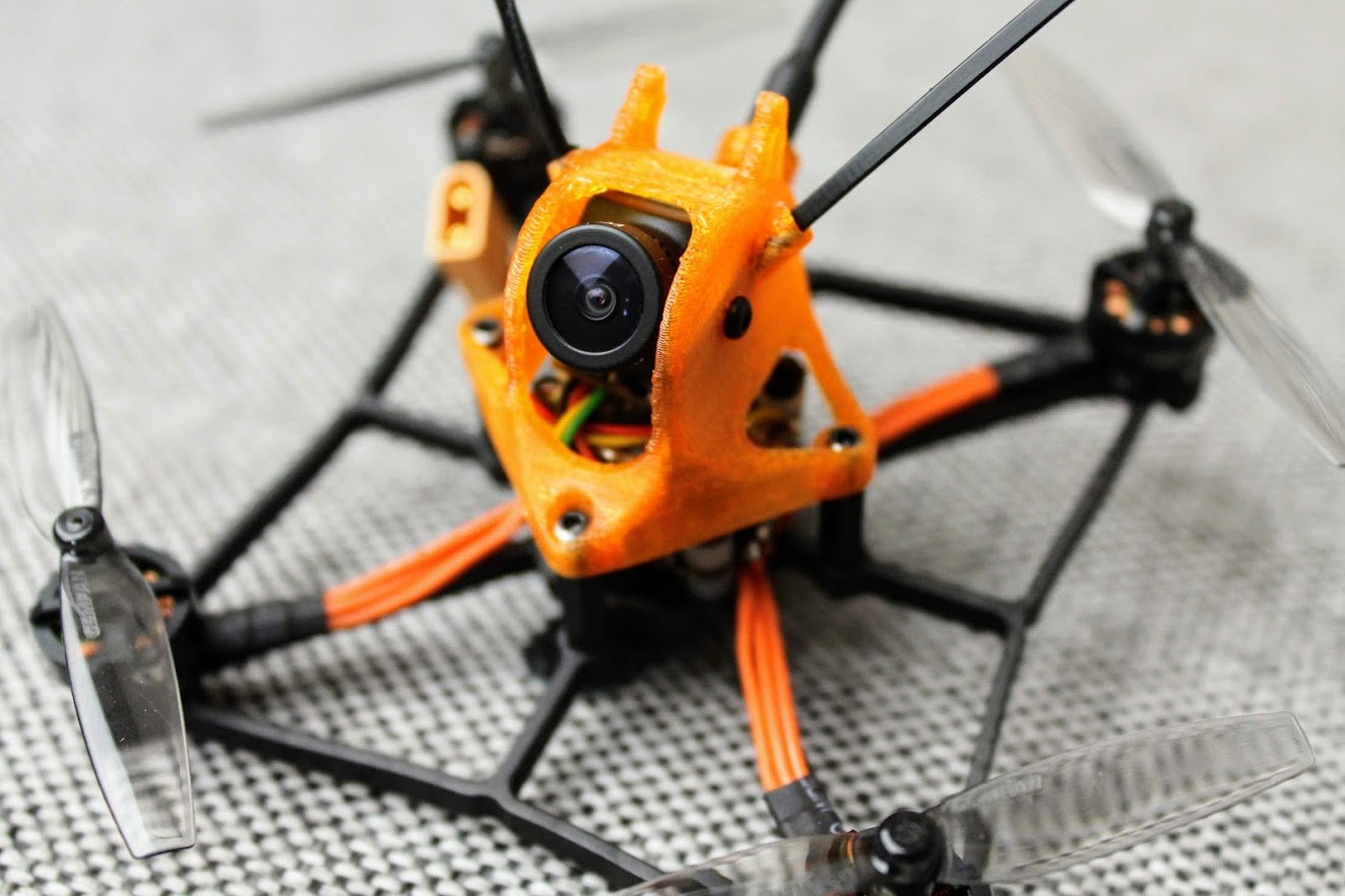
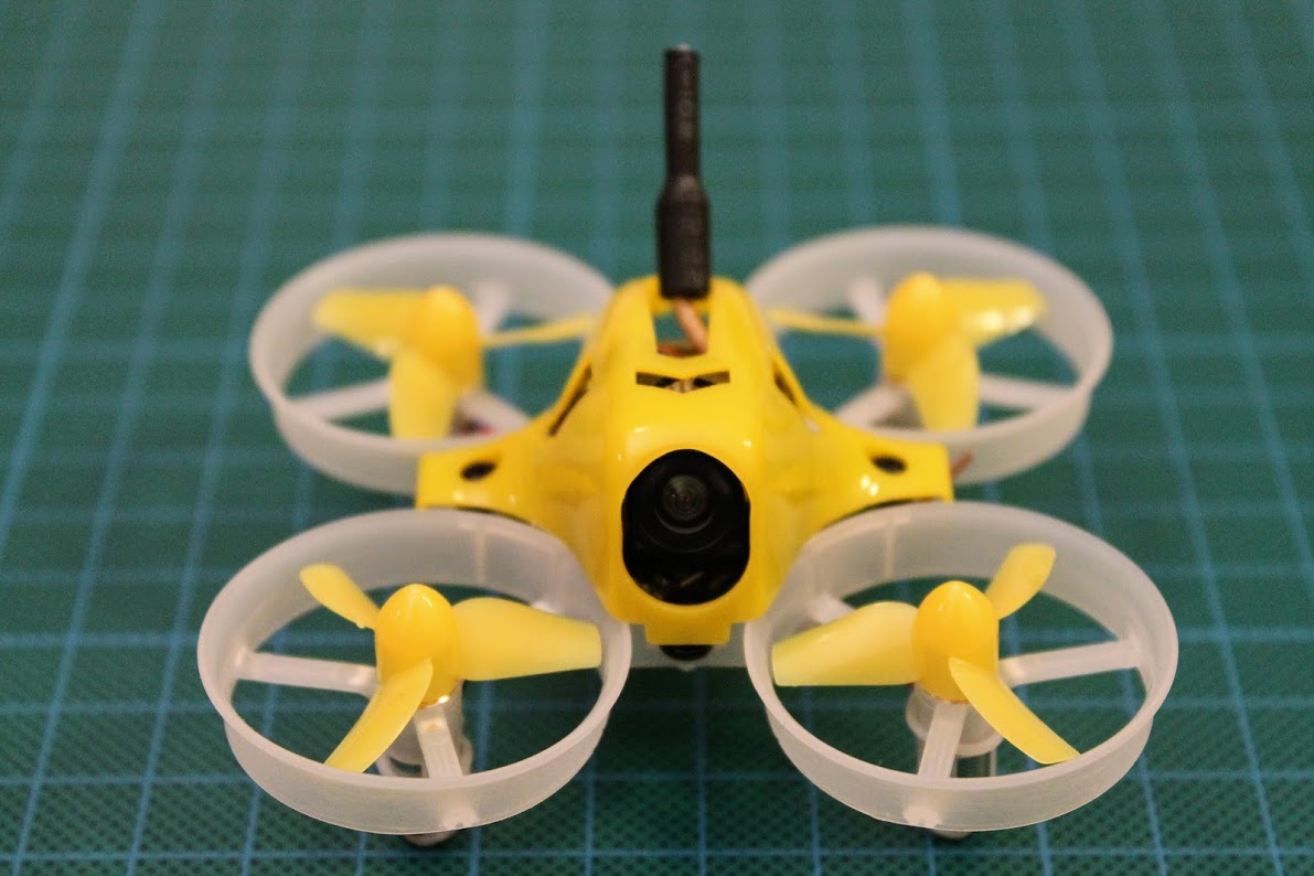
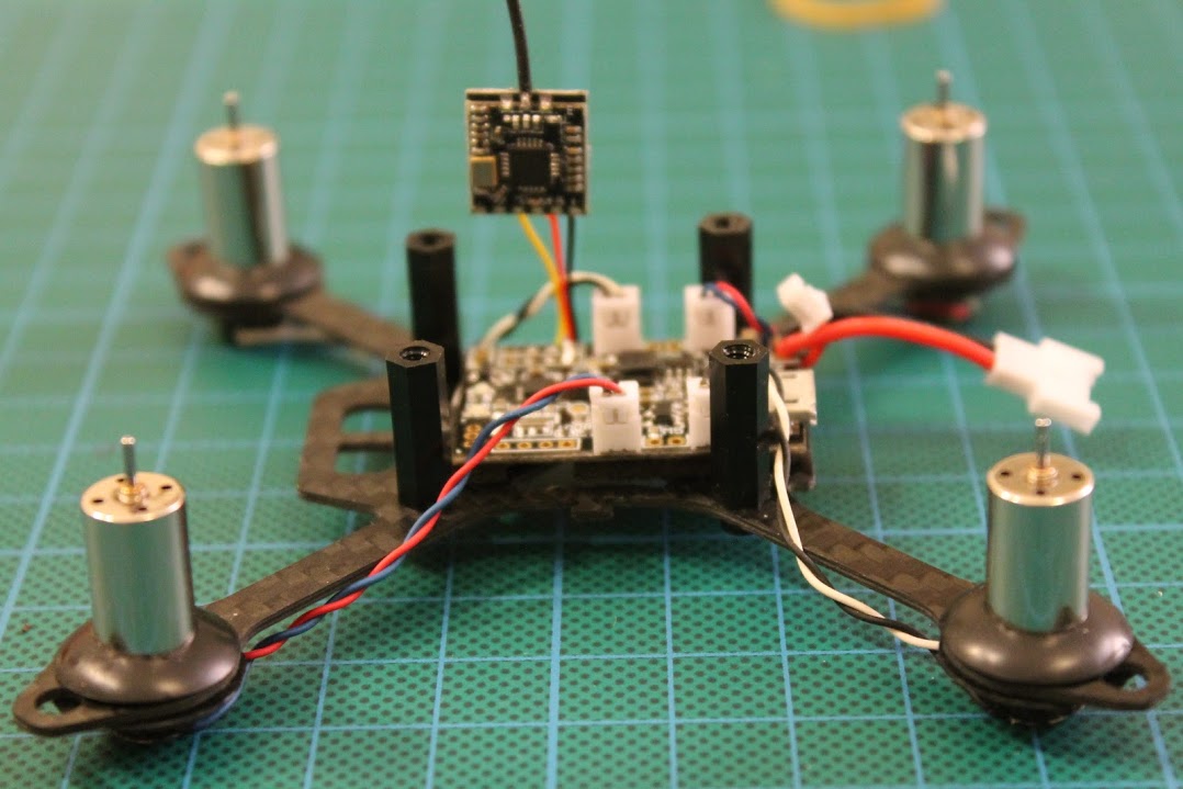
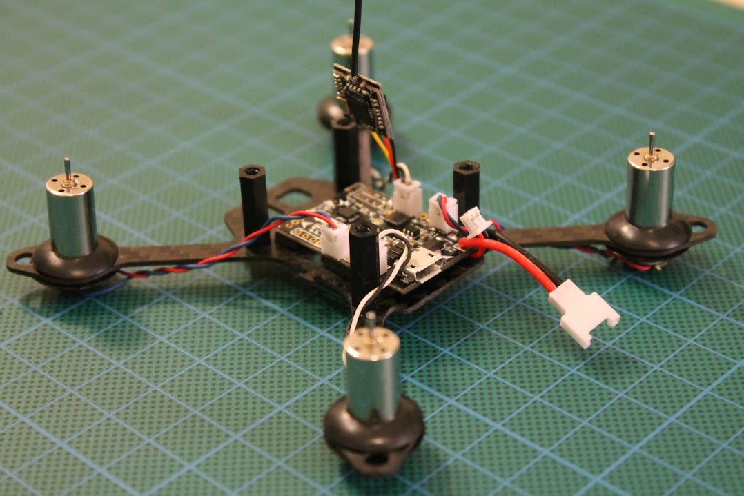
“Super slim” PCB variant of the ExpressLRS TX module fits easily in the JR case. Should also fit into the JR Nano case or even inside the radio as internal module.
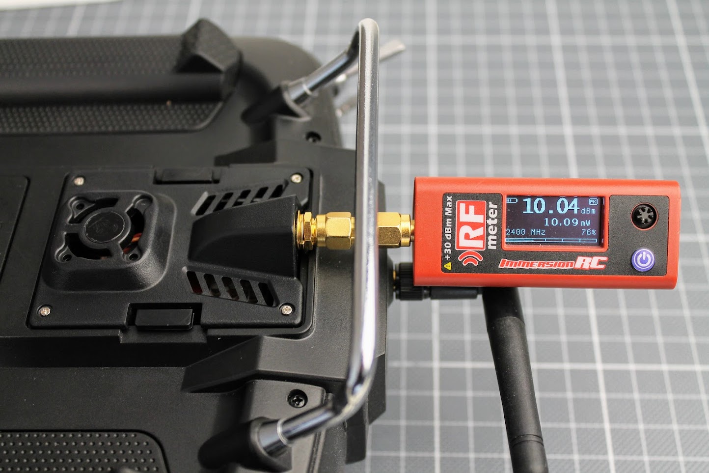
Power output tests
It is curious what RF power output does DIY ExpressLRS module gives. I have connected the ImmersionRC power meter to the antenna output of the DIY ExpressLRS module. The ExpressLRS module RF power output was set to 10mW, Dynamic power set to OFF. I’ve measured the exactly the 10mW of the power output.
At the 100mW output setting I’ve measured the 115mW output. 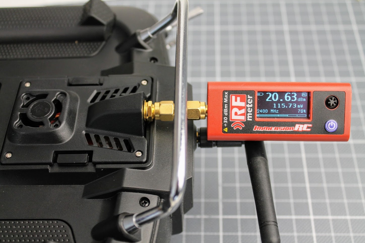
And at the 250mW?setting my RF power meter measured?255mW?of the RF output.?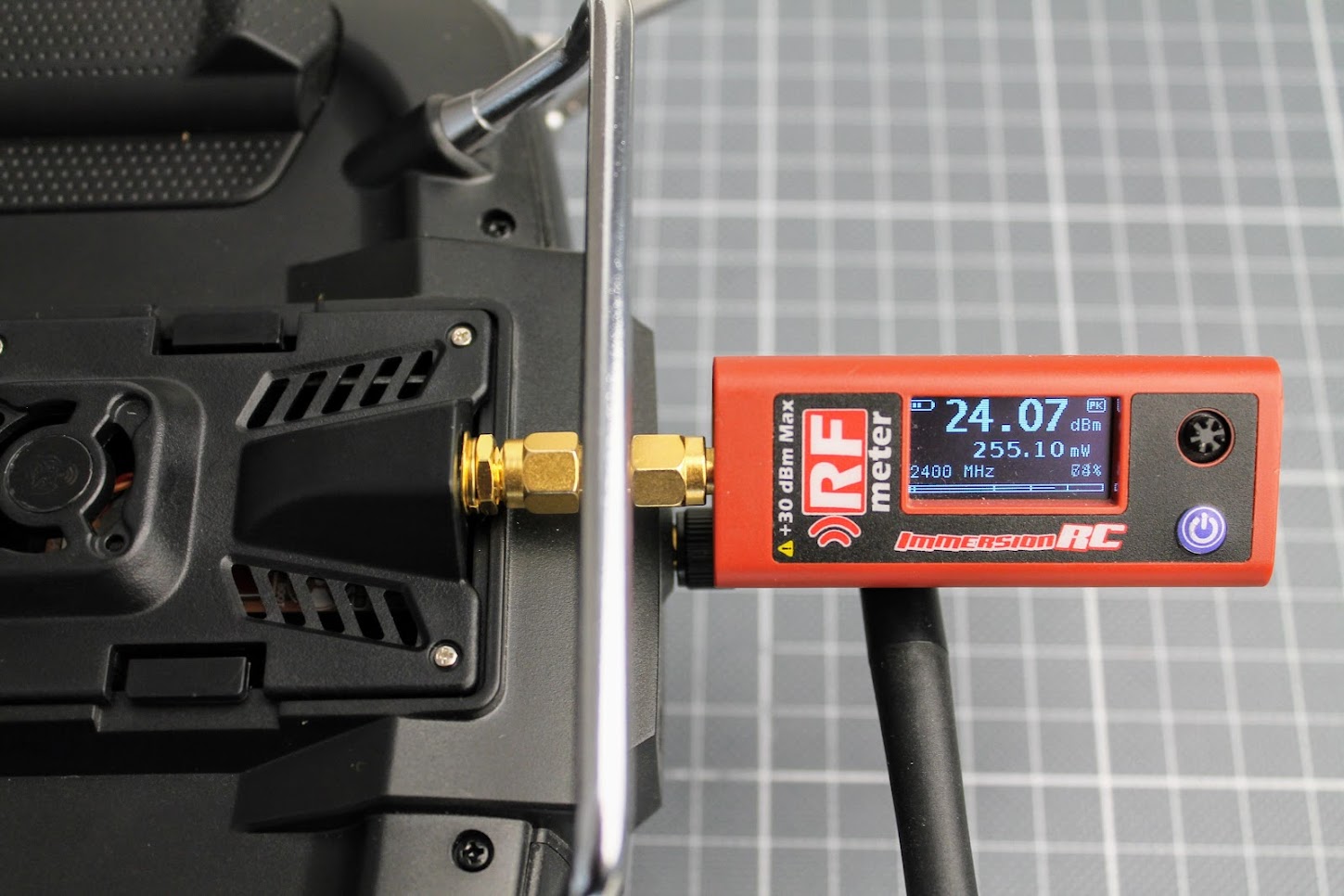
The 250mW output is stable, E28-2GM27S RF module does not heat up too much so no fan is needed.
?
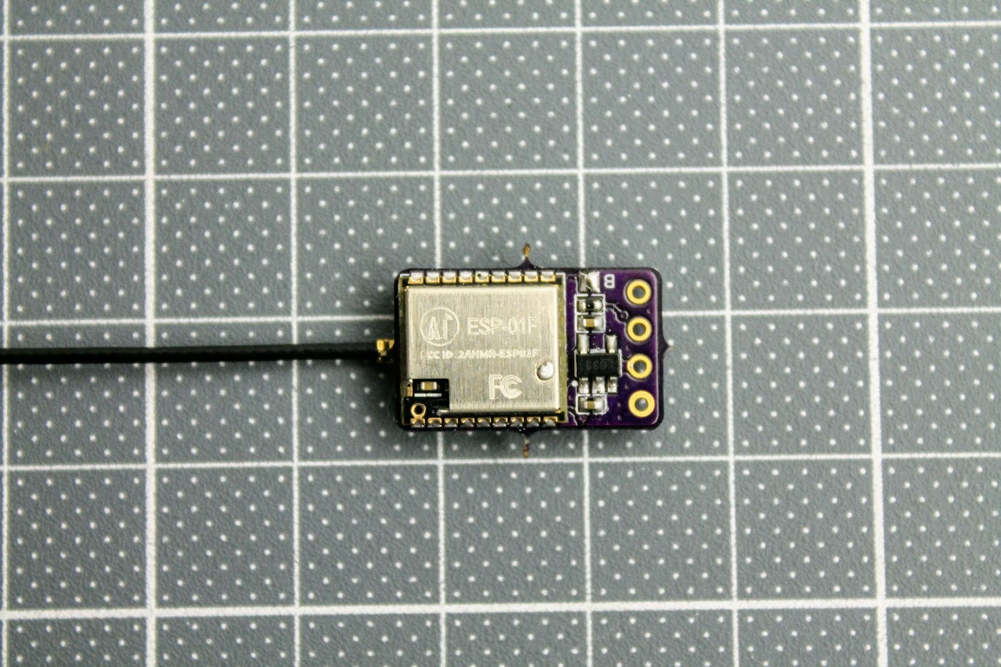
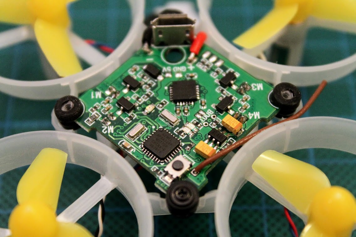
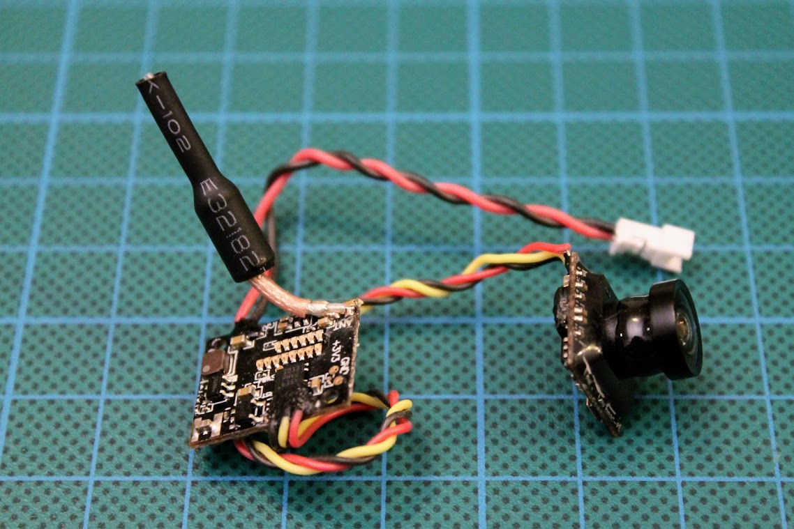
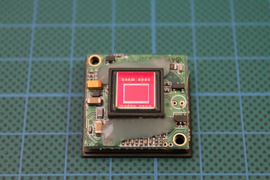
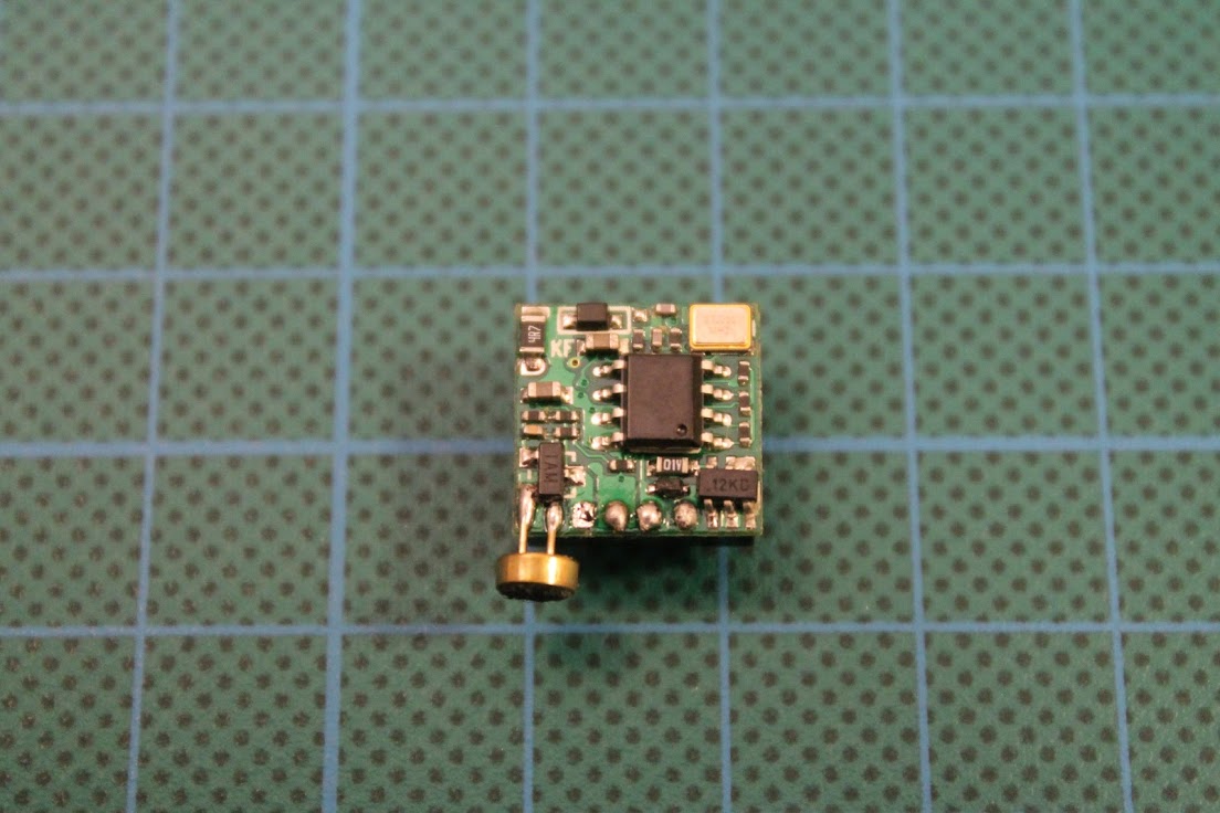
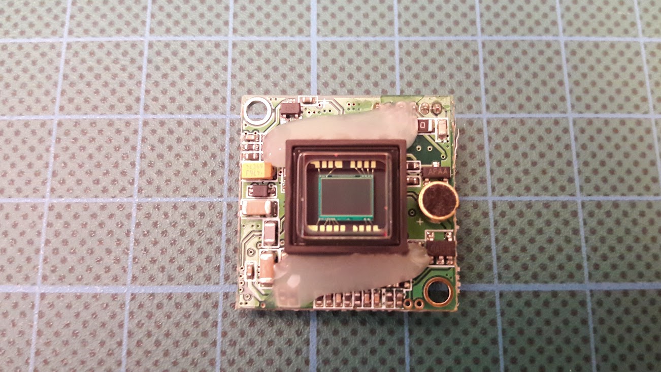
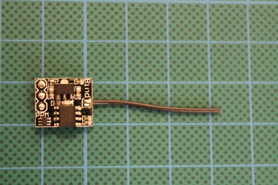
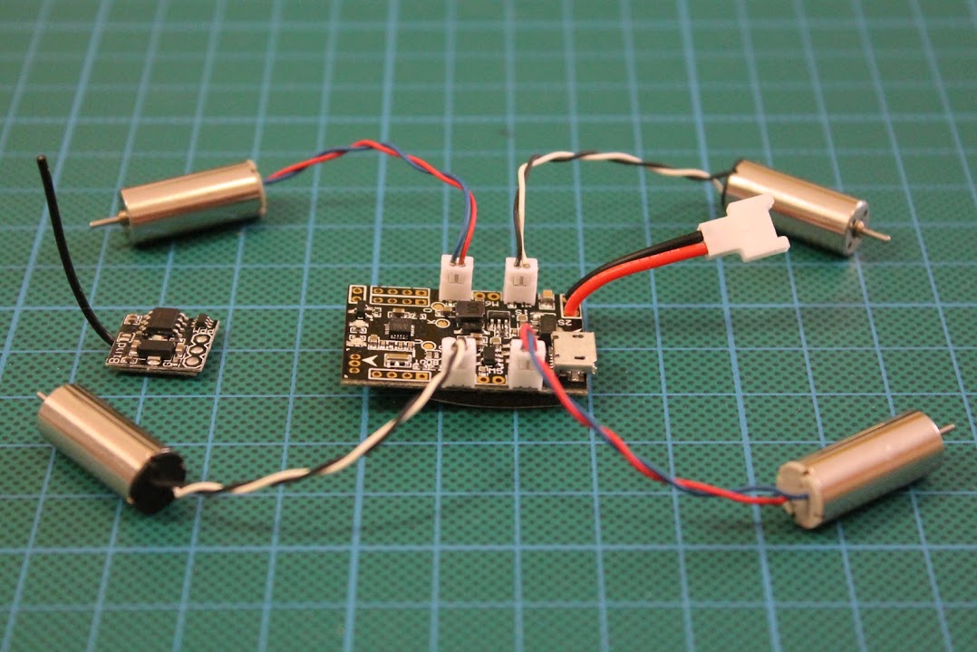
DIY ExpressLRS Nano Receiver
Remarks
DIY ExpressLRS Nano receiver uses 0402 size components. They are small as 1.0 x 0.5mm (0.040″ x 0.020″). It is almost impossible or at least it is very hard to solder these components without hot air gun. You will need proper equipment and soldering skills for soldering this small RX.
RX Parts list
I have ordered the PCB on?OSH Park?(https://oshpark.com/shared_projects/yYtMC9D3).?The cost of PCB was $3.00?for 6pcs. That’s $0.5 for one piece. Cheap as beans.
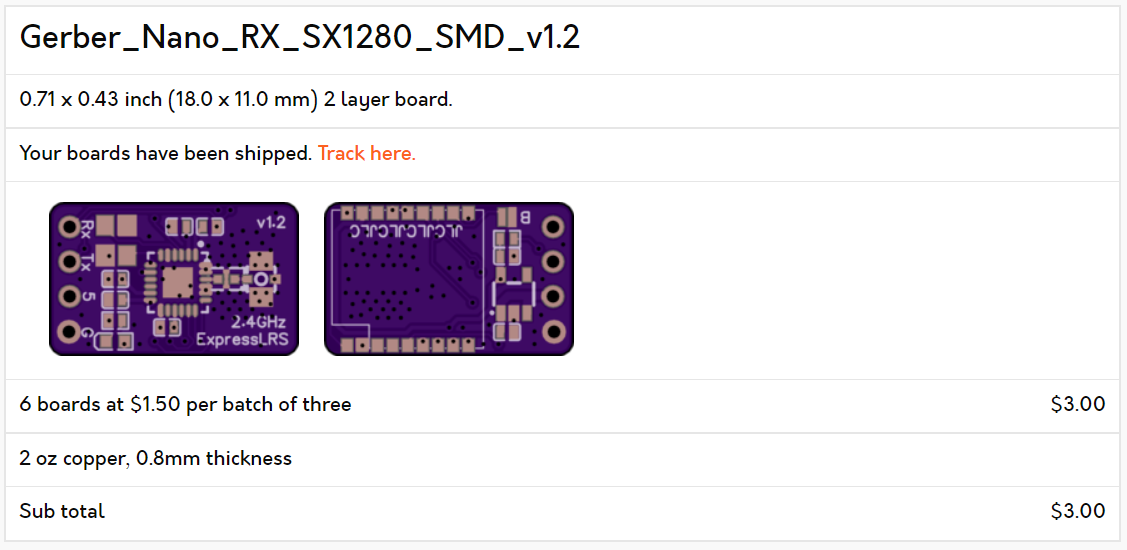
The original gerber files needed for PCB manufacturing can be found here: https://github.com/ExpressLRS/ExpressLRS-Hardware/…/PCB/2400MHz/RX_Nano
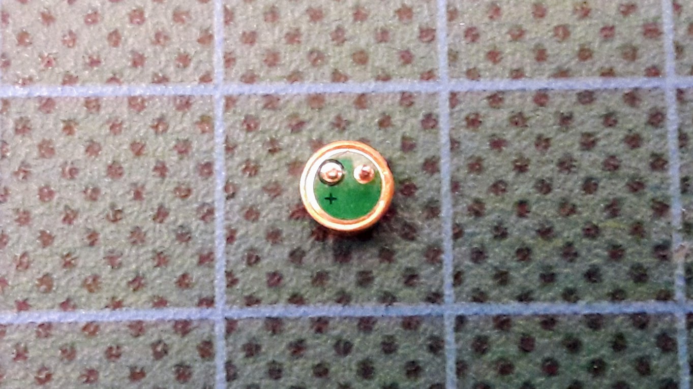
The EBYTE E28-2G4M12S module is used as the source for the cheapest SX1280 chip.?
EBYTE E28-2G4M12S on Aliexpress: https://www.aliexpress.com/item/1005001808615493.html
ESP-01F module – https://www.aliexpress.com/item/1005001808615493.html
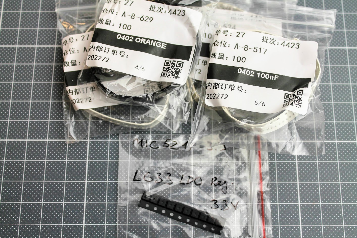
Some 0402 size components
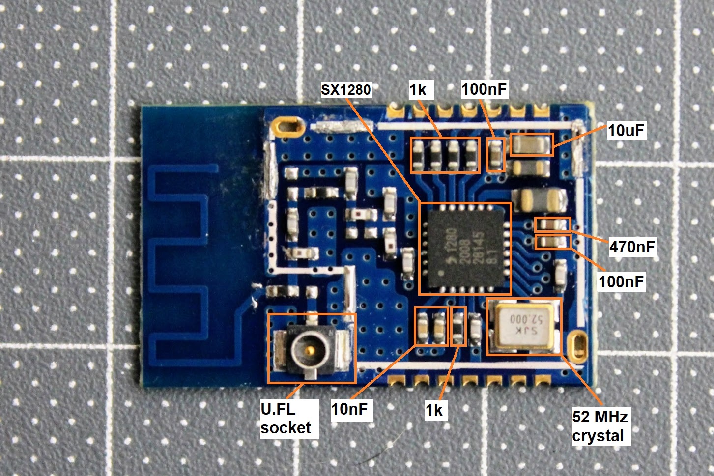
De-cased EBYTE E28-2G4M12S module.
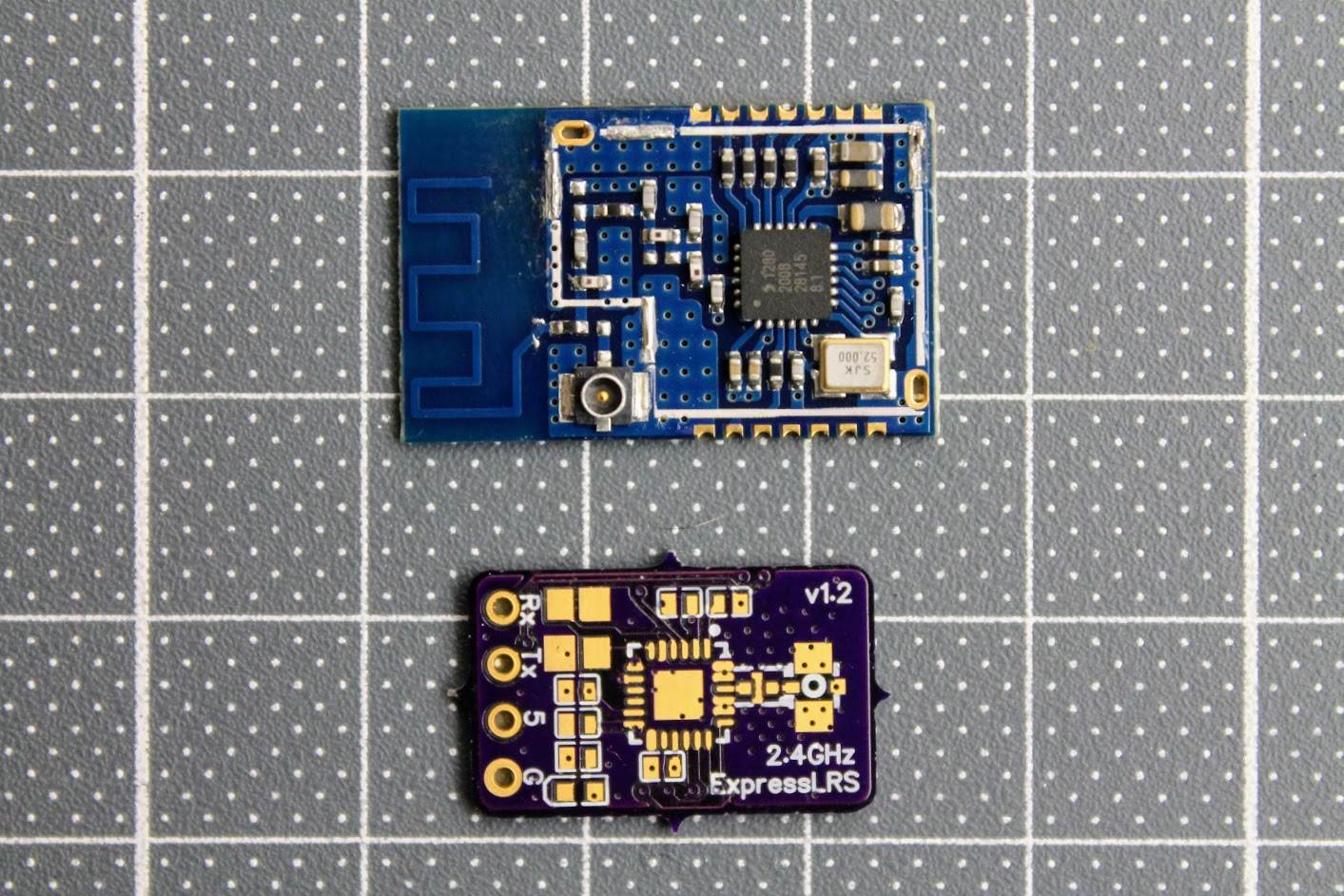
Here is the diagram of the EBYTE E28-2G4M12S module components for reuse in ELRS receiver.
The only other components you need to get are:
0402 size LED diode, 0402 size 1uF and 2.2uF capacitors
MIC5219-3.3 or MIC5319-3.3 voltage regulator – https://www.aliexpress.com/item/33047428186.html
ESP-01F module – https://www.aliexpress.com/item/1005001808615493.html
2.4GHz low pass filter (ballun) – 2450FM07D0034T or 2450FM07A0029T. These are harder to get. Look for it on Mouser or DigiKey.
You will definitely need the RX antenna also.
Build process
The PCB and the components are so tiny, that you need definitely need the magnifying glass, hot air soldering gun, precision tweezers and SMD soldering paste. You will have to apply the soldering paste, place the SMD components on the back side of the receiver first, solder them with a help of hot air gun and then repeat the same on the top side of the receiver.
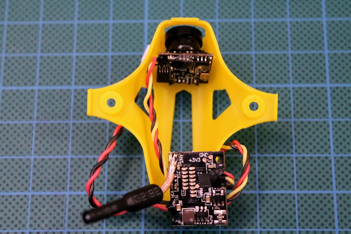
Photos of the soldered DIY ELRS Receiver.
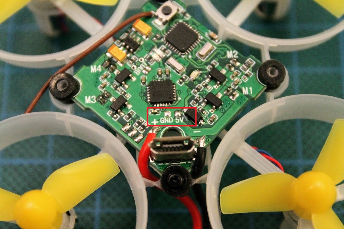
After the ESP-01F module is soldered, you need to solder the RX, TX, 3.3V and GND wires. Connect these wires to the corresponding pins on the FTDI or any other USB to serial adapter. You can also use Arduino Uno board for USB to serial adapter. Don’t forget to short the BOOT pads on the RX board for flashing the firmware by UART.
Read more about the flashing the ExpressLRS here:
ExpressLRS Open Source Long Range radio control system – Complete Guide
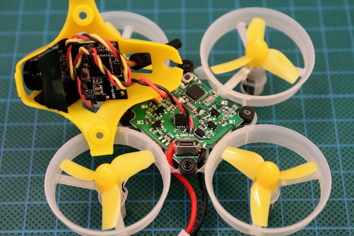
DIY ExpressLRS receiver ready for flashing.
Making the ExpressLRS transmitter and receiver by yourself is definitely a fun task, however you should evaluate your skills of the SMD soldering in case of the making the super small receiver.
]]>Parts list
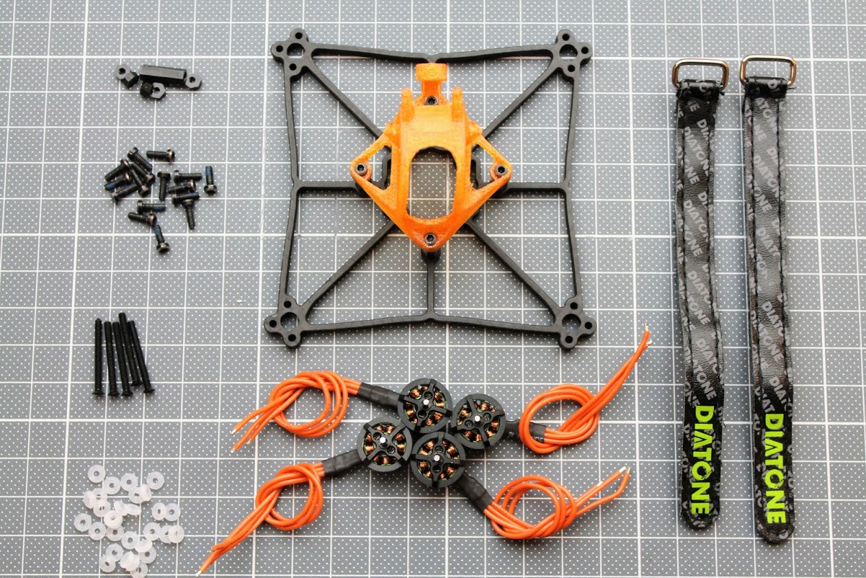
Diatone GTB239 frame kit – $16.58: https://www.banggood.com/DIATONE-GTB229-GTB239-Cube-2_5inch-Frame-Kit-FPV-Racing-Multi-Rotor-Parts-p-1552955.html
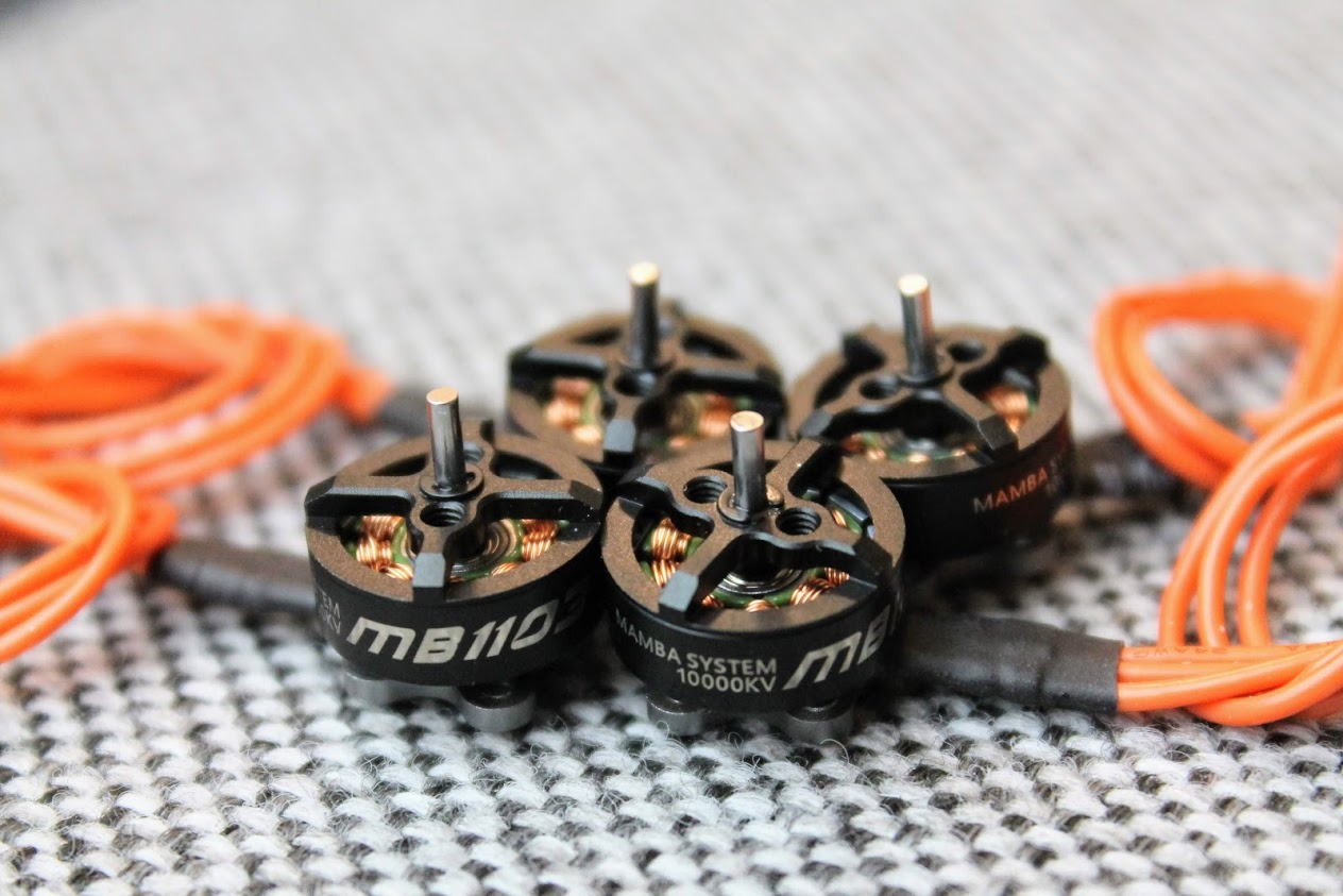
Diatone Mamba MB1103 10000kV motors – $10.99 x 4: https://www.banggood.com/MAMBA-1103-6500KV8500KV10000KV-2-3S-Motor-For-FPV-Racing-RC-Drone-p-1553986.html
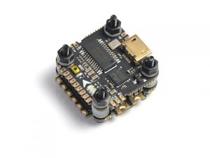
Diatone Nano Mamba stack – $42.84: https://www.banggood.com/Diatone-MAMBA-134-F411-Flight-Controller-MPU6000-Dshot6002-4S-STACK-BEC-5V1_5A-p-1530339.html
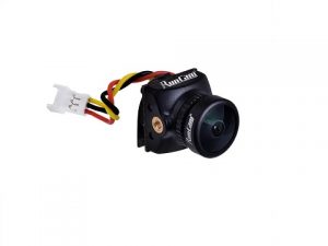
RunCam Nano 2 FPV camera – $20.50: https://www.banggood.com/RunCam-Nano-2-13-700TVL-1_8mm2_1mm-FOV-155170-Degree-CMOS-FPV-Camera-for-FPV-RC-Drone-p-1469656.html
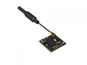
RunCam TX100 Nano VTX – $14.99: https://www.banggood.com/RunCam-TX100-Nano-5_8G-37CH-25mW100mW-VTX-Smart-Audio-IPX-IPEX-for-RC-Tiny-Drone-Mini-FPV-Camera-FC-p-1597688.html
Total parts: $138,87?
Parts in detail
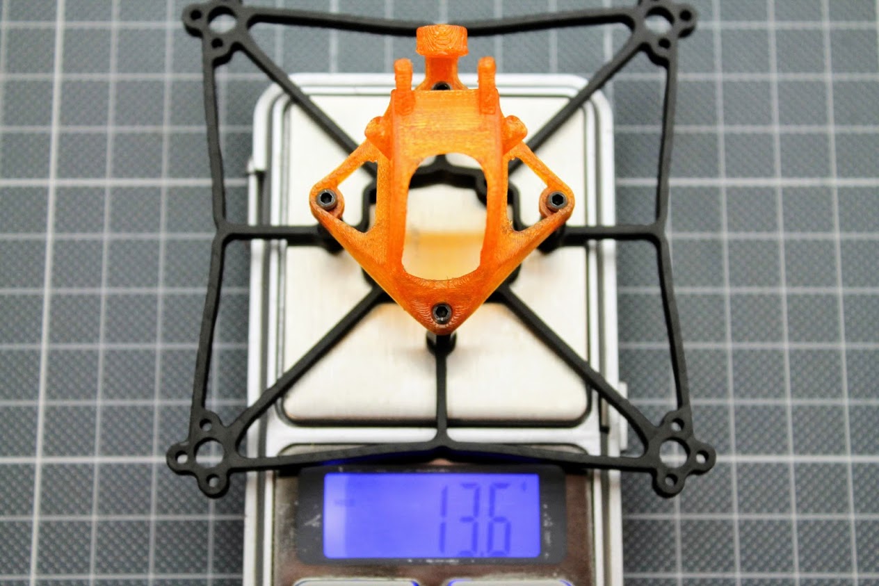
I have selected the GTB239 frame instead of the GTB229, despite the fact that I’ll be using it with 2S lipo batteries, because it is stronger and less likely to break in crashes. The additional 2 grams weight is not such a big penalty.
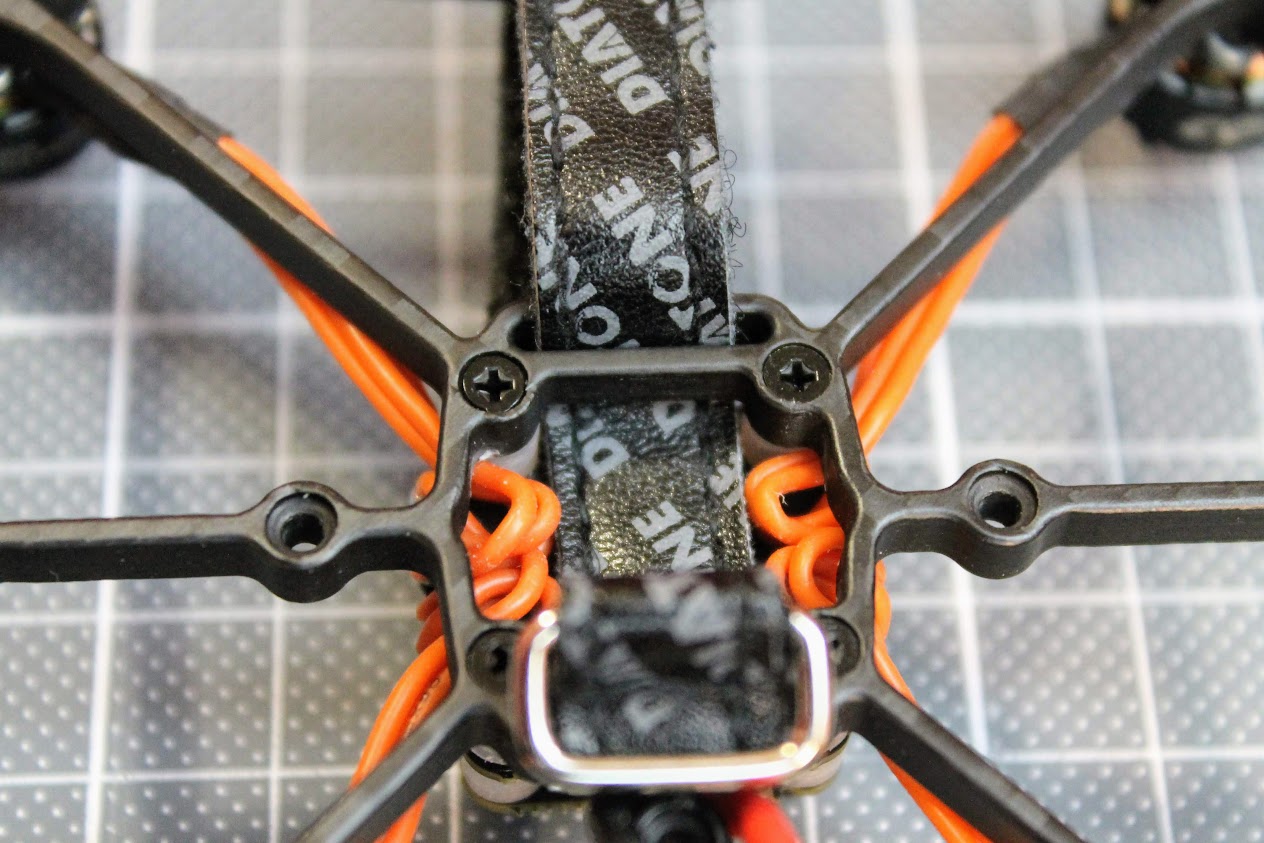
Frame kit comes with the frame, 3D printed canopy, two battery straps, a set of the M2 screws, plastic standoffs, plastic long M2 screws for mounting the FC and silicon rubber washers for vibration dampening.
Frame and canopy weights 13.6 grams total.
I have selected the Mamba 1103 motors with the higher 10000kV rating, hoping it will give me more speed on the 2S battery.
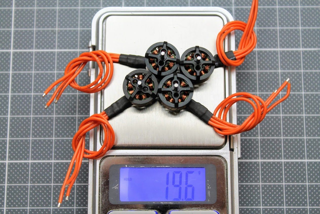
Motors weight 19.6/4=4.9 grams each.
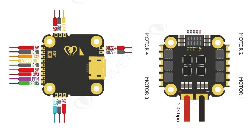
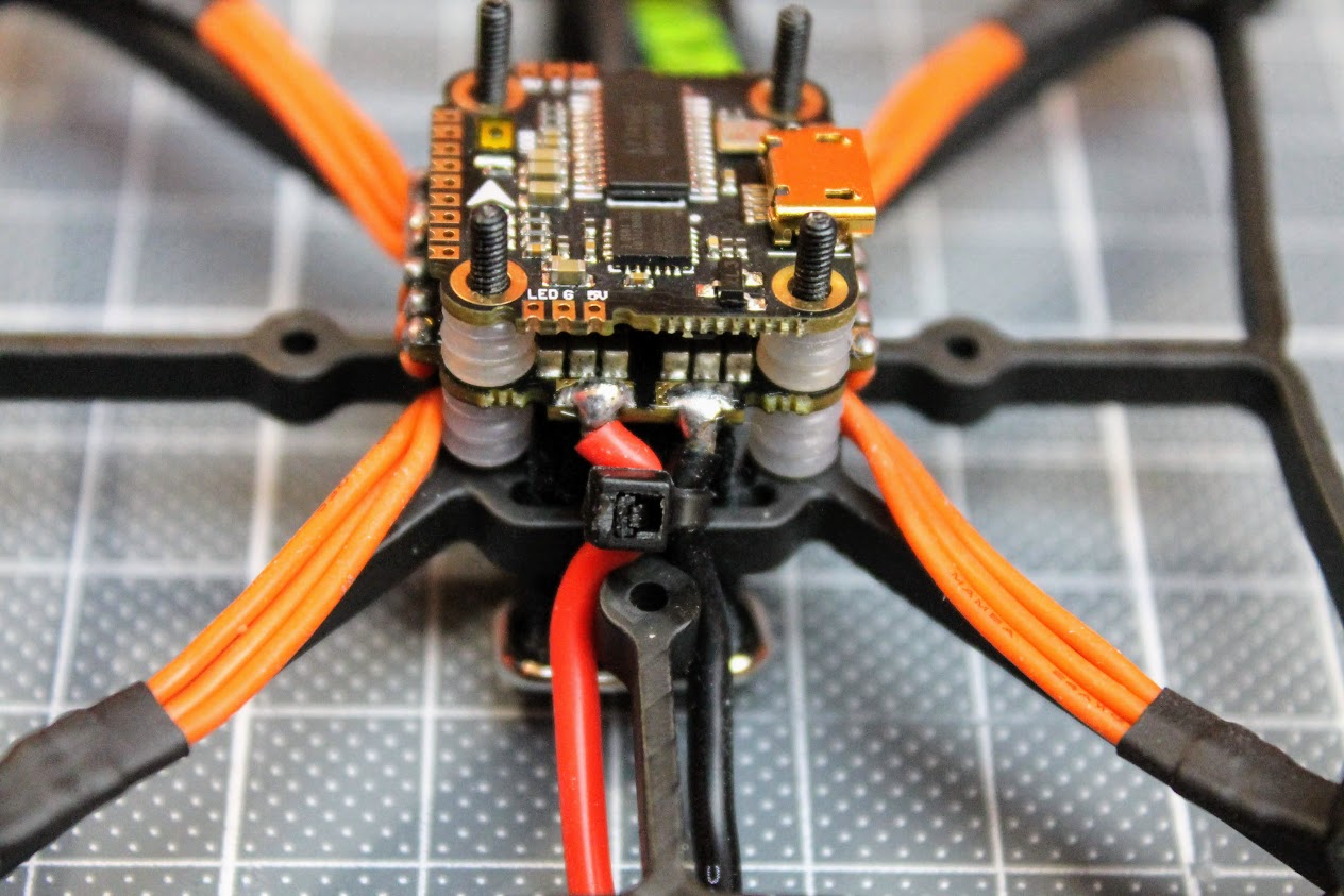
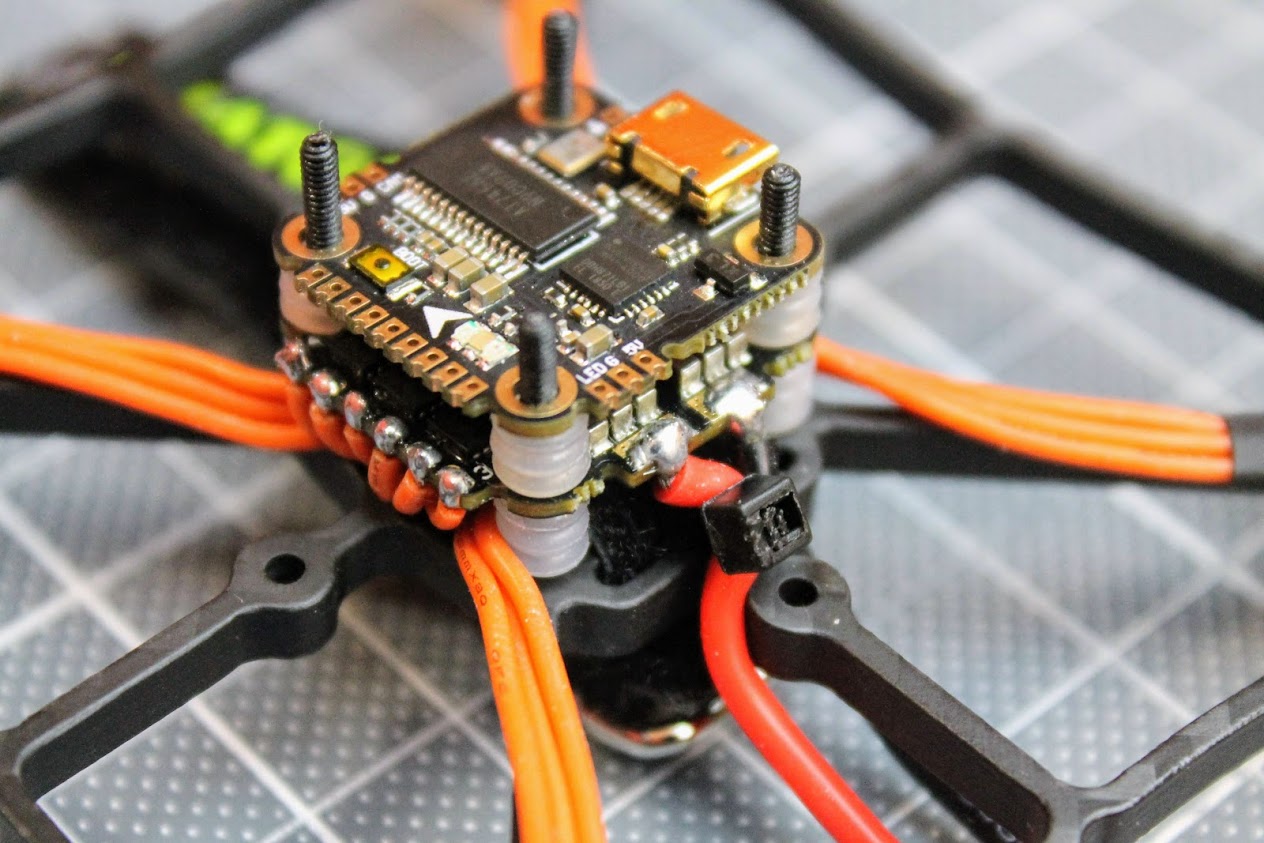
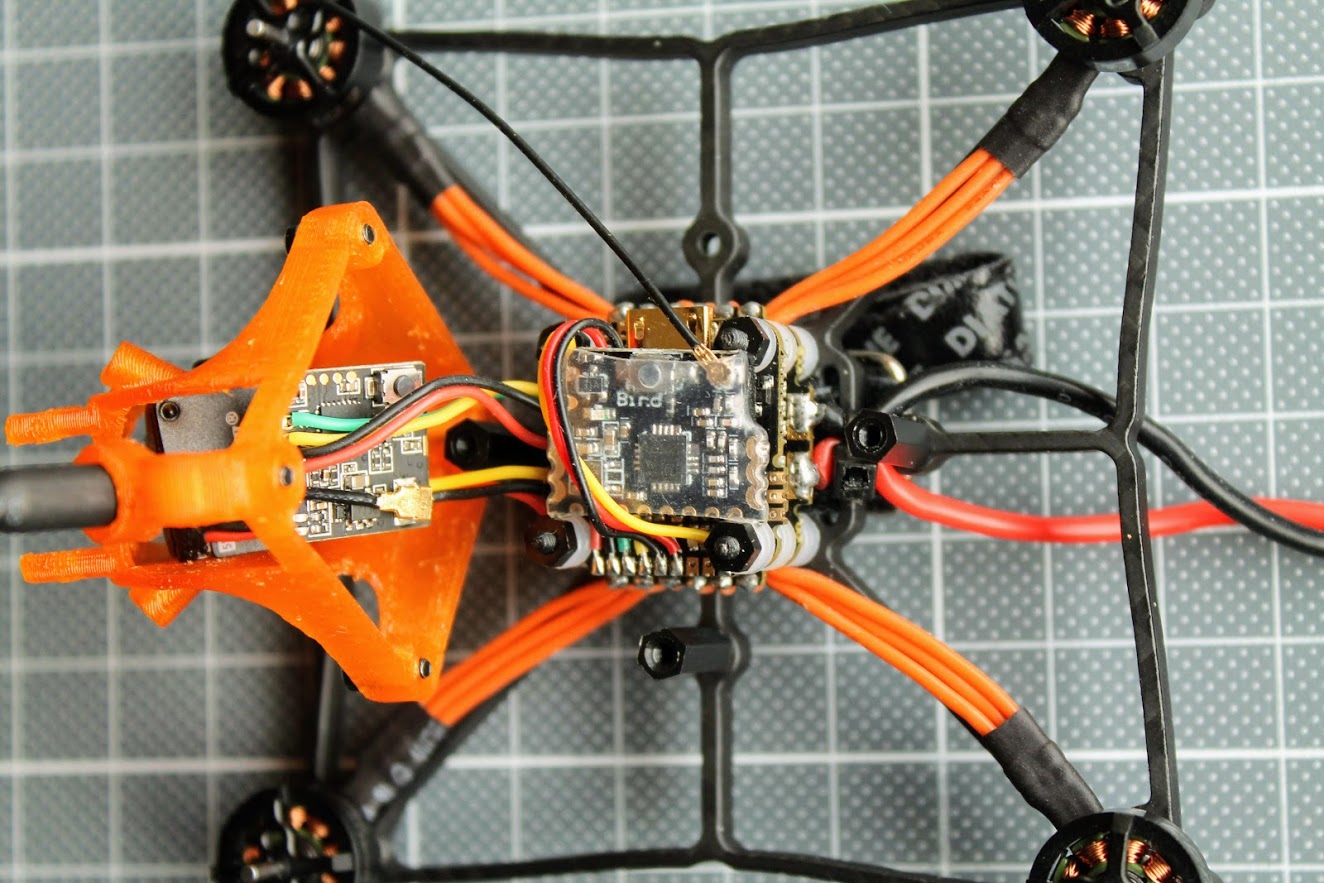
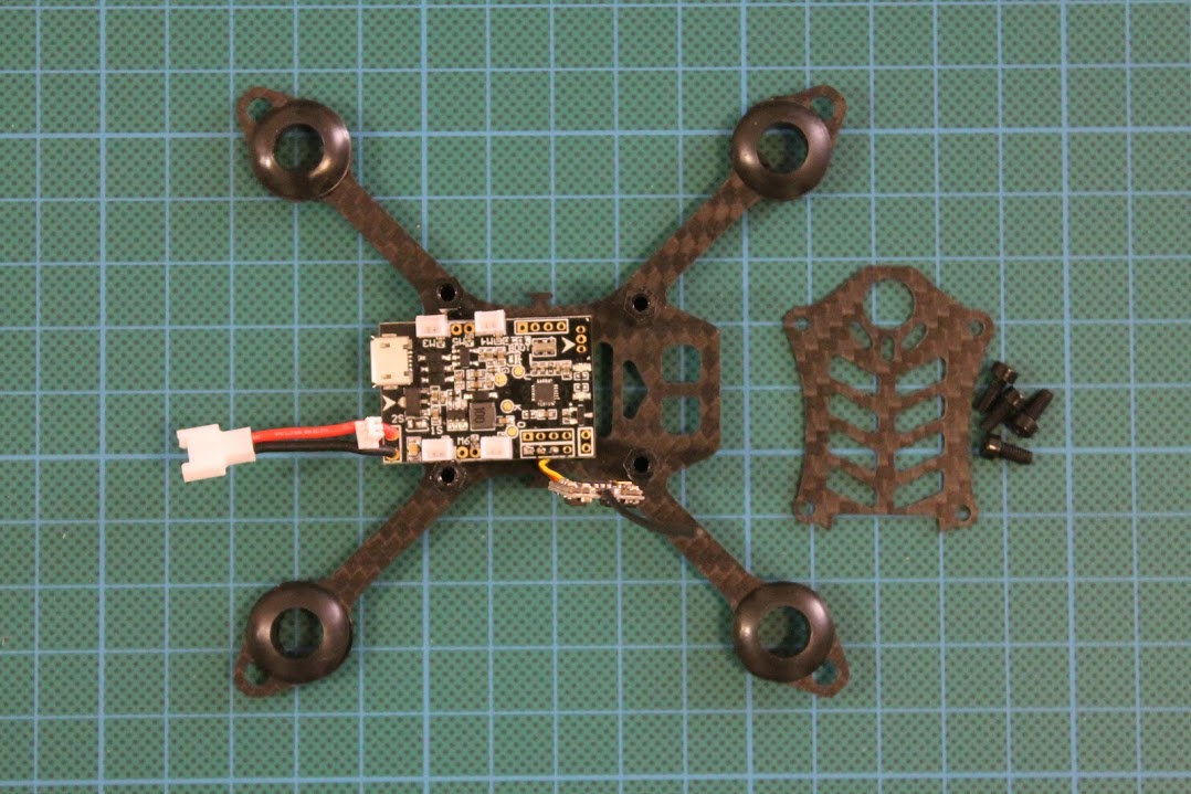
Diatone GT239 frame has mounts for 16×16 and 26x26mm size FC boards. I’ve decided to go with Diatone Mamba F411 Nano size stack.
Diatone Mamba F411 Nano stack connection diagram (this is V1.0 stack):
RunCam Nano 2 camera was selected because this is the camera in the original Diatone GTB229/239 and because I wanted to try it out. I have purchased the camera with 1.8mm lens and NTSC format. My preferred video system format is PAL, but there were only NTSC option at the moment.
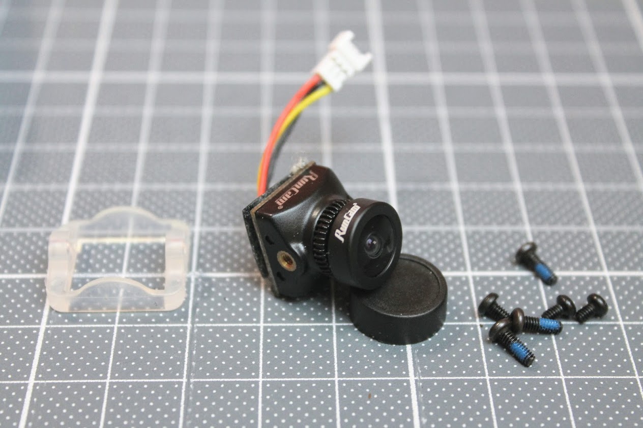
Camera weights 3.9 grams.
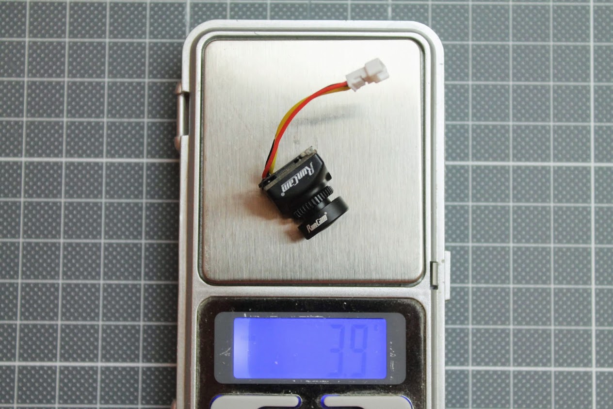
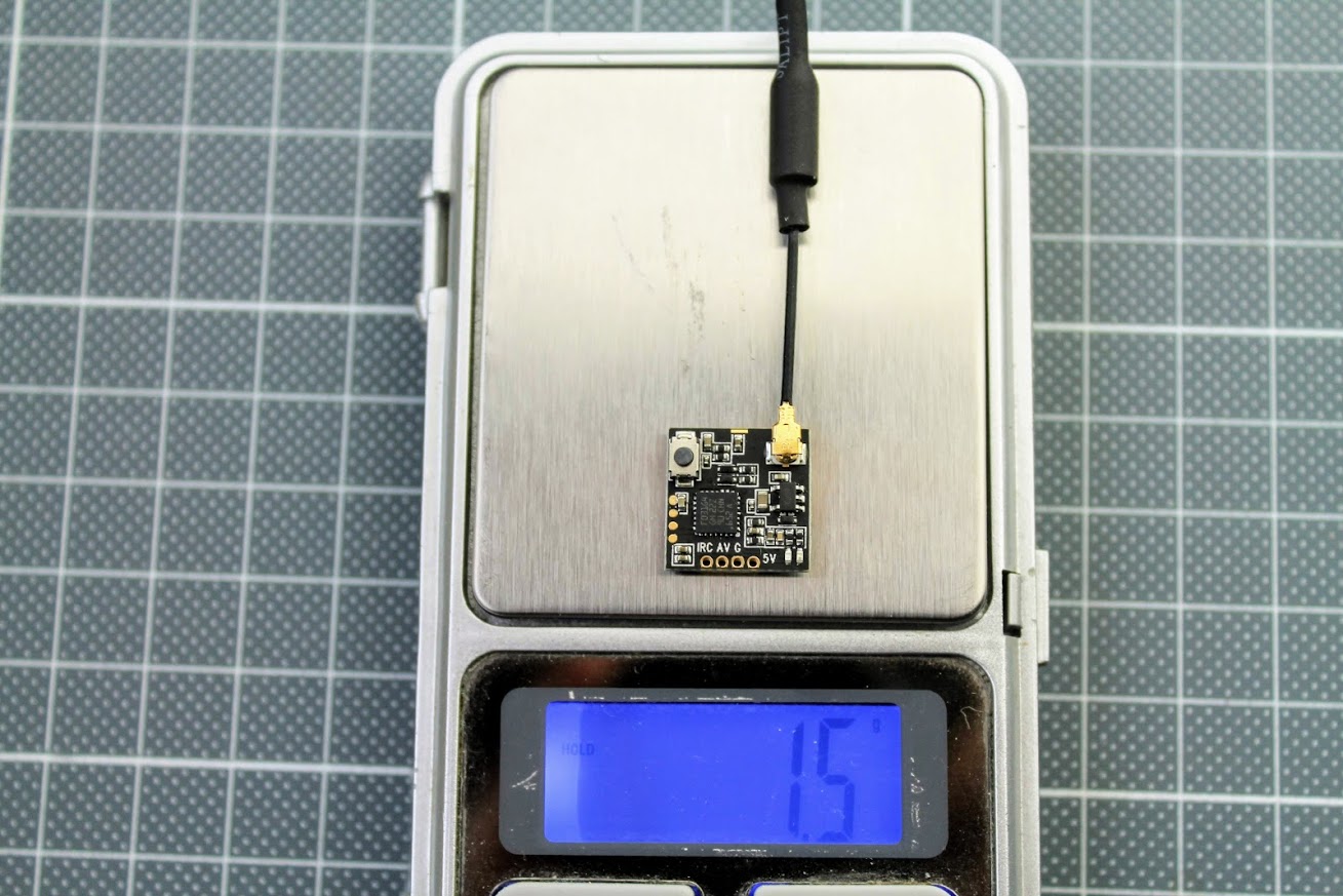
RunCam TX100 was selected as it is very small, fits right behind the Nano camera as its dimensions are the same (14x14mm). Read more about this VTX here: Review: RunCam TX100 Nano VTX.
RunCam TX100 weights only 1.5 gram with the dipole antenna.
Build process
I have mounted the Mamba 4in1 ESC with the 4 plastic long M2 screws with the countersunk head. It would be better if the screw was made from metal, but these screws were supplied with the frame kit and I didn’t have the metal M2 countersunk screws. We will see how they will hold in the crashes.
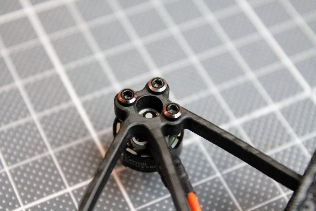
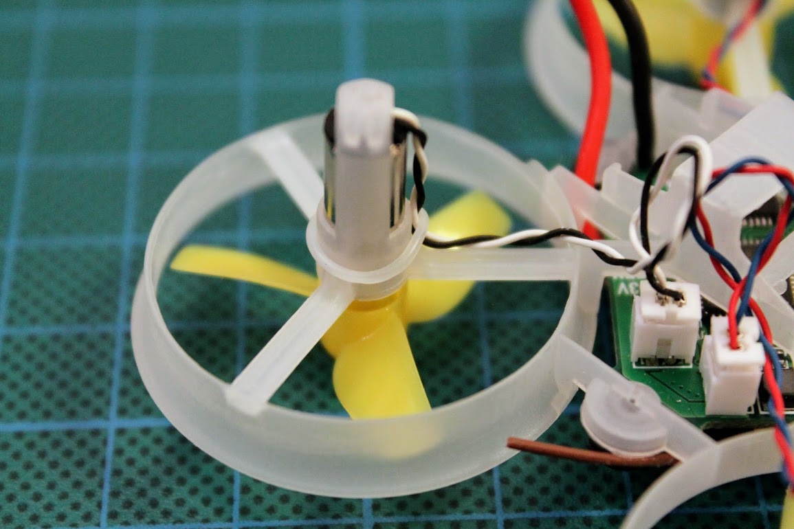
Then screwed the each motor with 3 supplied M2 screws.
Routed the wires with some reserve
Cut the wires and soldered them to the 4in1 ESC motor pads. The exact order of the soldered motor wires does not matter much as we can change the rotation of the each motor in the ESC BLHeli_S settings.
Motors and 4in1 ESC mounted and motor wires soldered.
Soldered the silicone 18AWG power wires with the XT30 connector. Zip tied power wires before the frame arm to make sure the wires will not be torn out with the solder pads in the case of the severe crash.
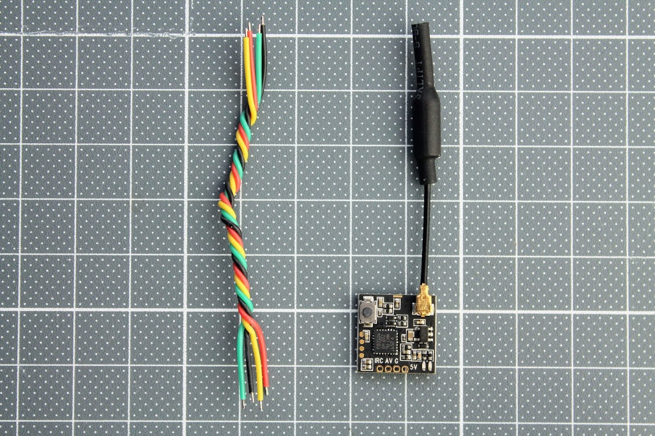
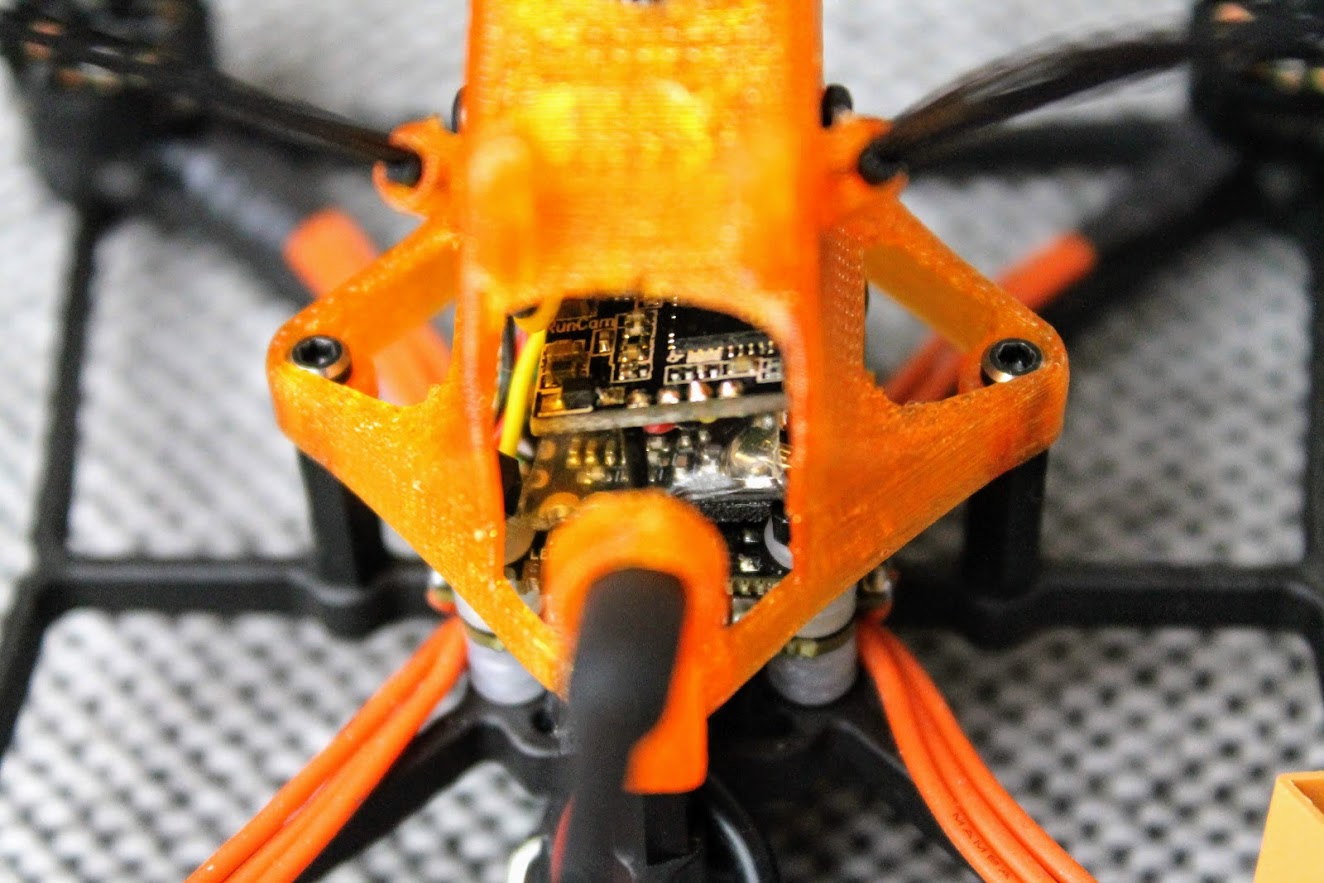
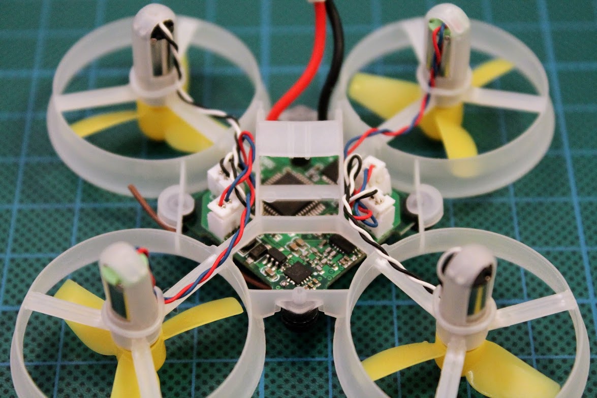
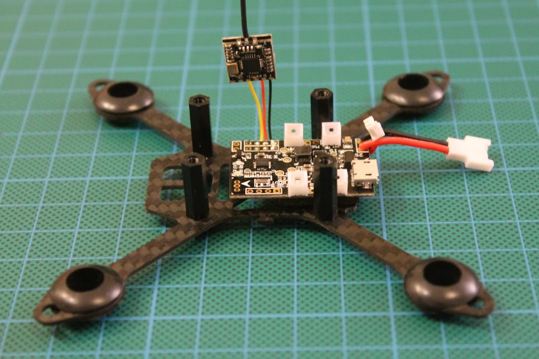
Soldered the RunCam Nano 2, RunCam TX100 VTX and FrSky D8 receiver.
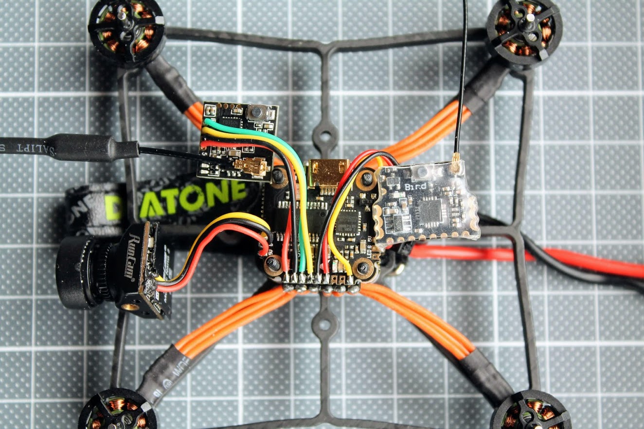
Camera and VTX fitted into the canopy and Frsky D8 receiver taped with double sided tape to the top of the stack
Runcam TX100 Nano VTX and Frsky D8 receiver fits inside the canopy with ease.
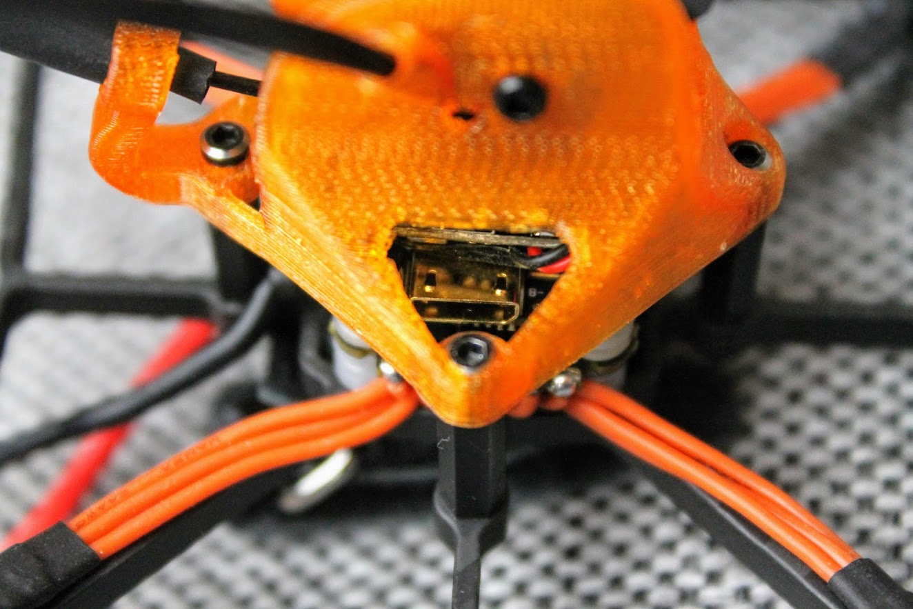
One downside is the vertical canopy standoff is in the way of the USB connector. You will need to unscrew and remove (temporarily) this standoff in order to access the USB port.
The view of the finished Diatone GTB229 quadcopter.
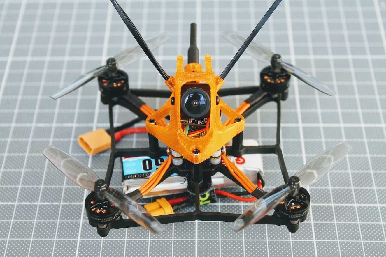
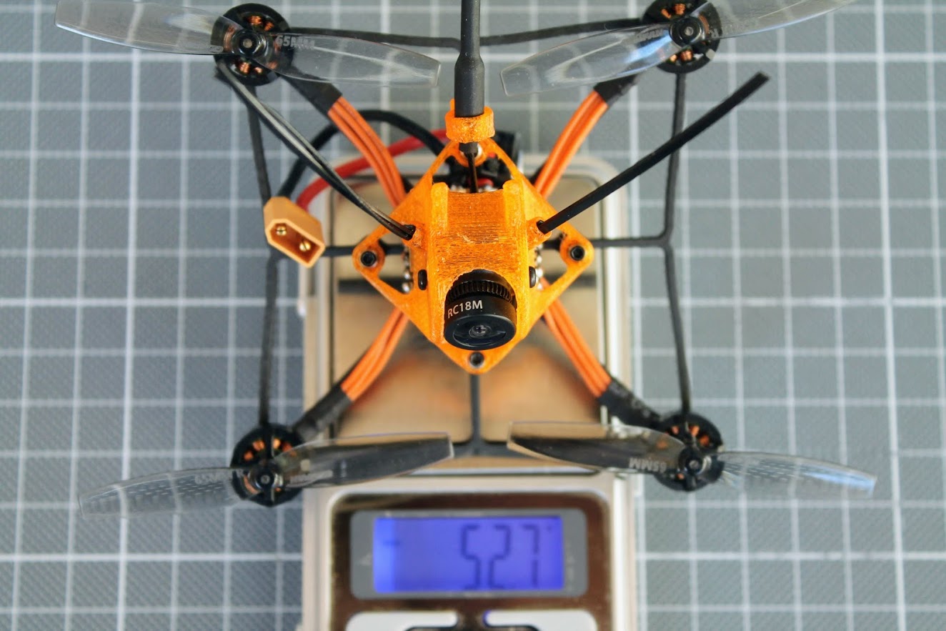
Total weight without the battery is 52.7 grams.
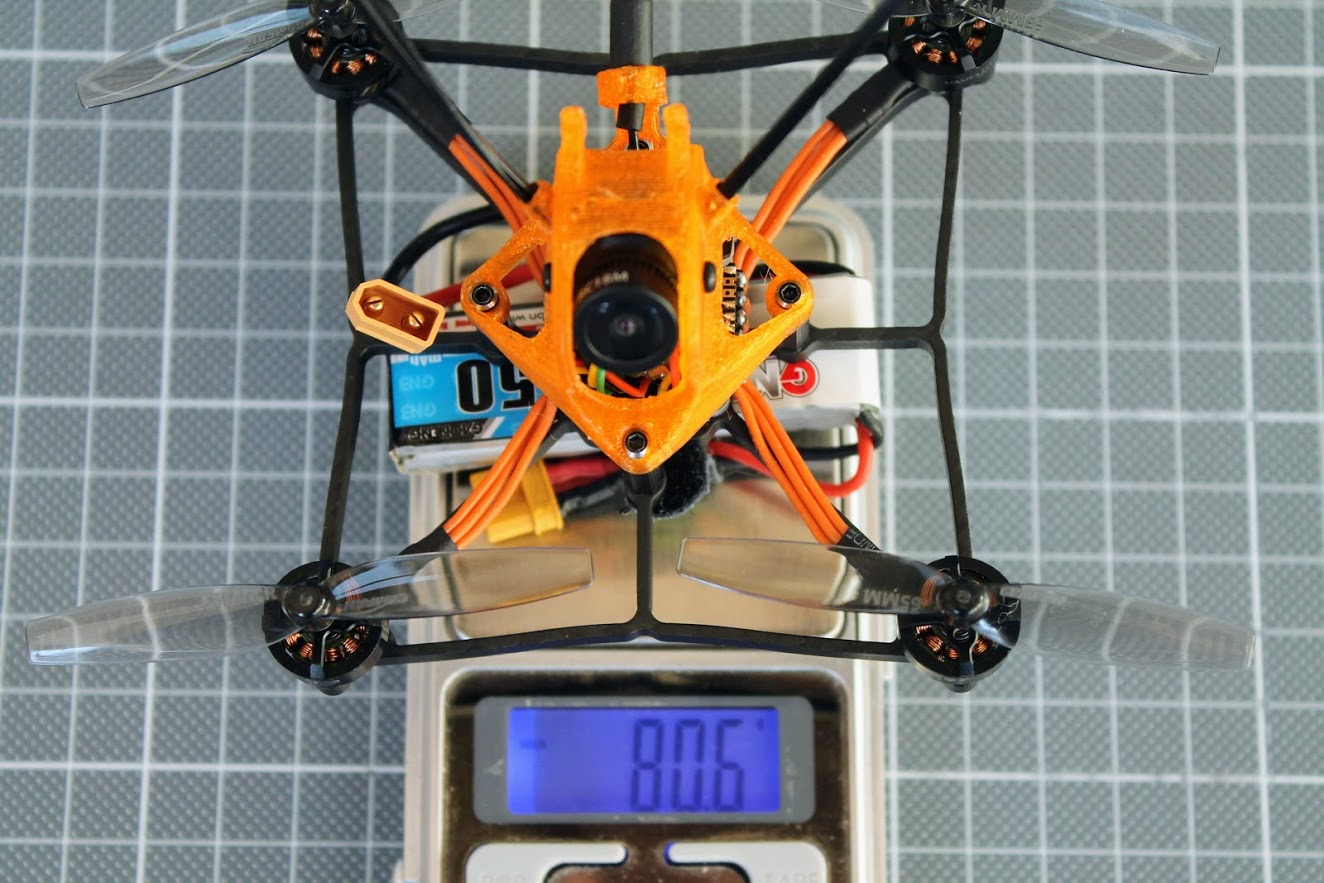
And the weight with the GNB 450mAh 2S battery is
Configuration
As soon as the motor wires and battery pigtail were soldered it is time to test the motors. I suggest powering the new build for the first time using the smoke stopping device. Plugging the battery for the first time is the most risky operation on any build.
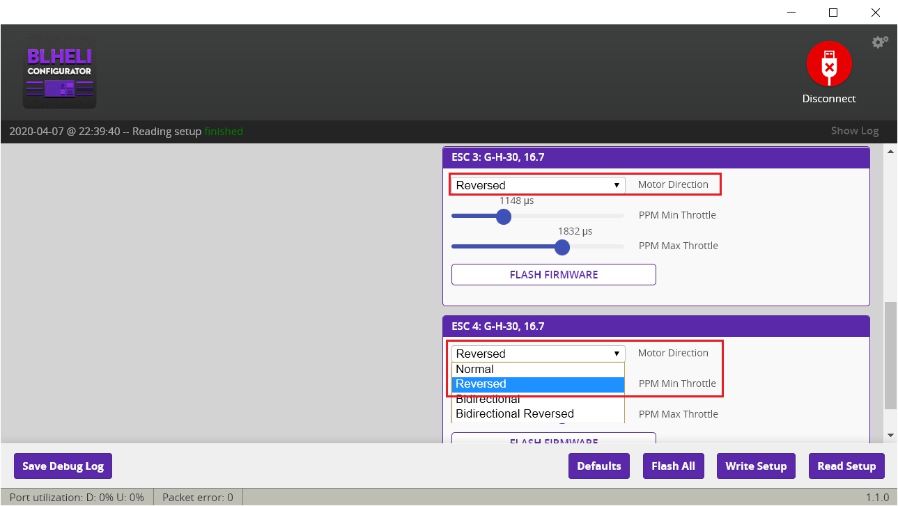
If everything was soldered correctly and the components are working as expected you should hear the ESC startup sound. Next thing is checking the motor rotation direction via Betaflight Configurator motor tab. I choose the reverse (or props-out) motor rotation configuration.
Individual motor check showed that I need to reverse the rotation of the motor in BLHeli Configurator. Set ESC 3 and 4 to be reversed.
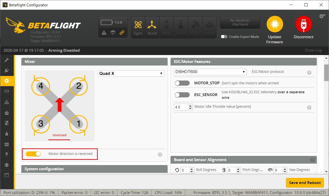
I’ve also set the reversed motor/propeller direction in the Betaflight Configurator (so called “Props out” configuration).
Other system configuration settings.
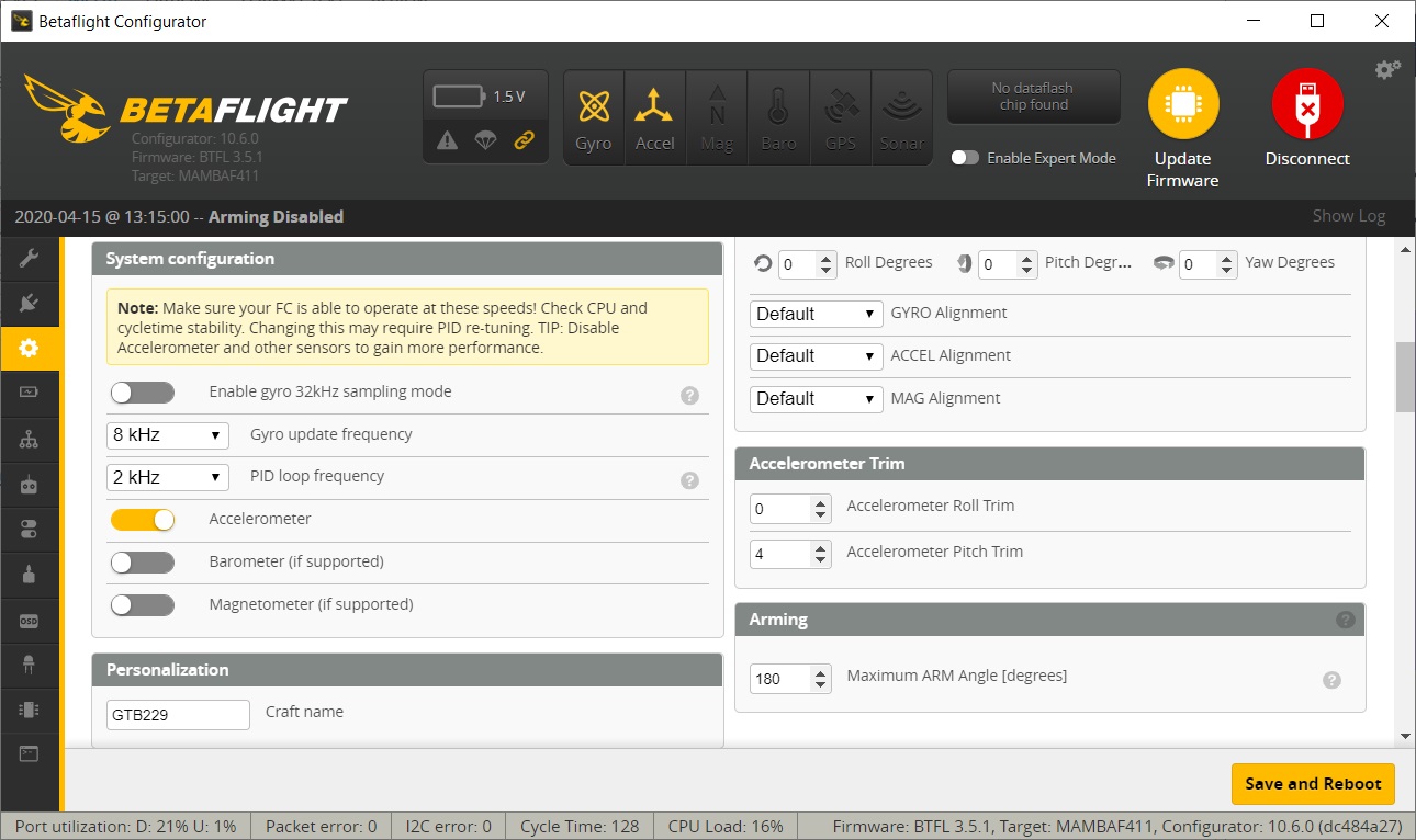
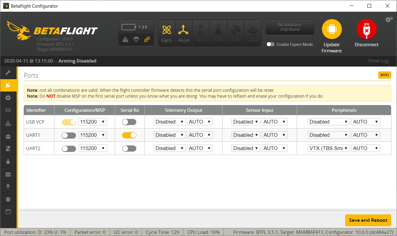
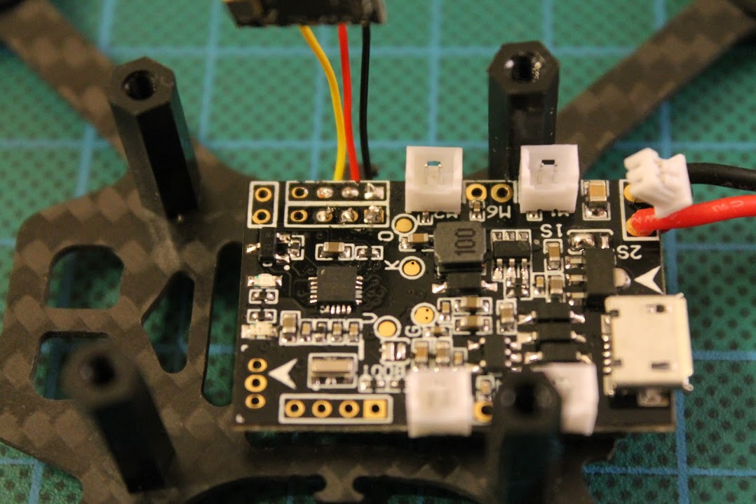
Receiver is connected to SBUS input on the UART1 and TBS Smartaudio VTX control on the UART2.
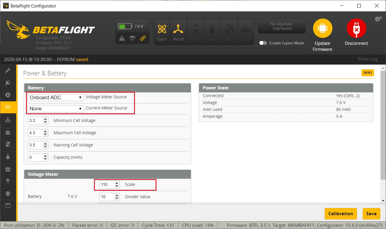
Diatone Mamba F411 Nano stack does not have the on board current sensor and the stack version V1.0 does not have any input for external current sensor (while version V1.2 has). So set the “Current Meter Source” to None. Voltage sensor scale is 110.
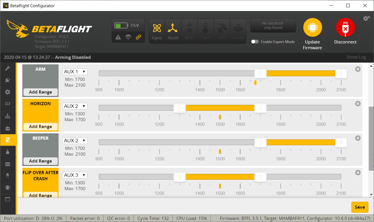
My preferred modes setup: ARM on AUX1 (rightmost switch), Horizon flight mode and Beeper on AUX2 (next to the AUX1 switch) and Turtle mode on AUX3
And some final shots of the finished quadcopter.
(The end)
]]>All the necessary parts.
Shopping list:
Tiny6 frame @ Gearbest: KingKong Tiny 6 65mm Micro Plastic Frame Kit – $6.99
Tiny6 frame @ Banggood: 65mm Frame Kit Sets For KINGKONG/LDARC Tiny6 Inductrix Tiny Whoop Racing Quadcopter -$7.99
Motors
Racerstar Black edition 4X Racerstar 615 6x15mm 59000RPM Coreless Motor with (1.25mm plugs) – $9.99
Racerstar Red edition 4X Racerstar 615 6x15mm 59000RPM Coreless Motor (with 1.25mm) – $11.99
Racerstar Purple edition 4X Racerstar 615 6x15mm 67000RPM Coreless Motor (with 1.25mm) – $16.99
Kados Insane edition 6MM CHAOLI (KADOS INSANE) 65000RPM 6X15MM – $9.99
Flight controller
@ Gearbest: FuriBee F3 32-bit Brushed Flight Controller – $17.99
@ Banggood: Eachine Beecore F3_EVO_Brushed ACRO Flight Control Board For Inductrix Tiny Whoop – $23.99
Upgraded Beecore with OSD: Eachine Beecore Upgraded V2.0 Brushed F3+OSD Flight Control Board For Tiny Whoop – $26.99
Total cost: from $34.97
First of all we will use original Tiny6 frame. It comes with white flexible frame base, canopy, damping rubber pads, screws, rubber bands and 4 pcs of 3 blade props.
Put the BeeCore F3 flight controller on the foam pads.
FC orientation: Battery connector and micro USB port should be located on the back side of the quad.
Fixate the flight controller with two screws – one on the from and one on the back. Left and right screws will be used to hold the canopy.
We have two options for FC mounting. One is use dampening foam pads that come with flight controller:
Another option is to use rubber dampers that cam with the Tiny6 frame kit. It’s a matter of the preference – foam dampeners make more softer fication and ruber dampeners are more stiff, but I went for rubber ones.
Rubber bands are for used to hold the motor wires close to the frame.
Thats how motors connected and wires fixed with rubberbands look like.
We have already made a flyable Tiny6. We can plug the battery, bind the transmitter and check how this little whoop flies. If it flys ok LOS (line of sight), we can now convert it to the FPV whoop. For this we need to add camera and VTX combo.
Camera and video transmitter shopping list:
From Gearbest
Camera: Turbowing TWC25 Micro 700TVL NTSC FPV Camera – $8.94
VTX: Turbowing 5.8G 48CH 25mW NTSC FPV Transmitter – $8.94
Or combo camera + VTX: Turbowing TX25 Split Micro 700TVL FPV Camera – $17.06
From Banggood:
Camera: 600TVL 1/4 1.8mm CMOS FPV 170 Degree Wide Angle Lens Camera PAL/NTSC 3.7-5V – $6.99
VTX: Eachine VTX01 Super Mini 5.8G 40CH 25mW FPV Transmitter – $9.99
Combo camera: Eachine TX01S NTSC 40CH 25MW VTX 600TVL Cmos FPV Camera for Tiny Whoop – $18.99
Total for camera & VTX: from $17.06
I have chosen the Eachine TX01S camera and VTX combo.
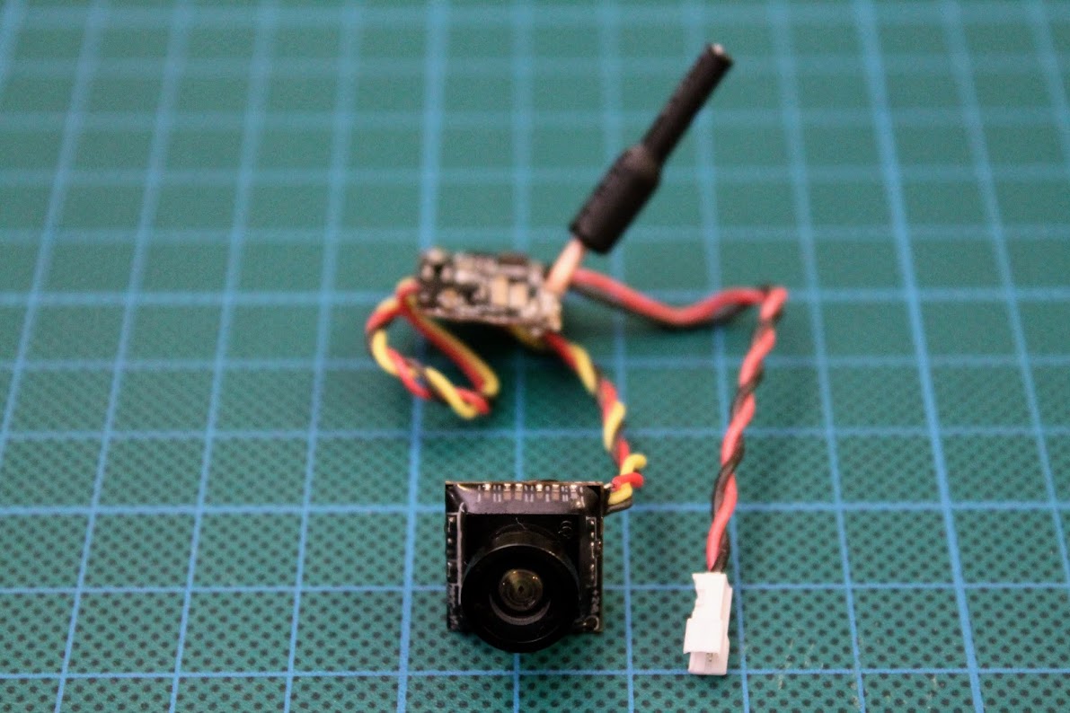
The Eachine TX01S camera fits the canopy nicely.
The only soldering you will need to do in this build is solder the VTX power lines. For this you trim the power leads and solder them to the marked pads.
I have attached the camera to the canopy with a help of double sided adhesive tape.
You see the all the FC status and the VTX channel and band LEDs through the holes in the canopy. Unfotunately you cannot change them withou removing the canopy.
Thats it, we have completed the Do-It-Yourself Tiny6 brushed tiny whoop. This was the easiest quad buid I’ve made so far. Almost no soldering required. You can complete this build easy and quickly.
Some photos of the completed Tiny6 whoop.
Older version of the HS1177
New version – HS1177 V2
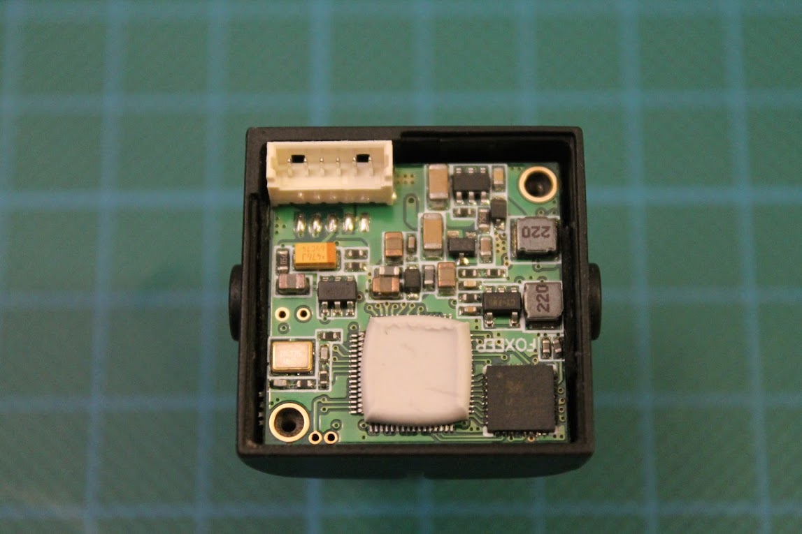
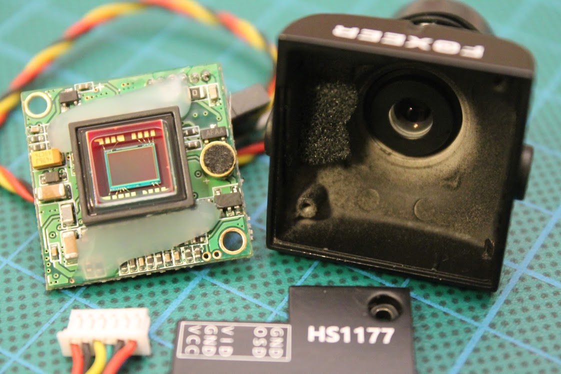
One user on RCG has dissasembled the camera and found that there is actually microphone on the PCB! I have dissasembled my HS1177 V2 camera and found that there is a place and circuitry for mic, but the microphone itself is missing. Looks like the first batches of this camera were sold with microphone onboard and fully capable of outputting the audio. The later batches have microphone removed.
So in order to make our audio mod we need to get the right microphone. It happened that I had micro CMOS camera with small electret microphone that fits perfectly on to the camera PCB.
The dimensions of the microphone is about 4.5×2.2mm. You can purchase 10pcs of such microphones from ebay for about $2.50 or 2pcs for about $1.
Solder the microphone while watching for polarity – plus on the microphone should be soldered to the plus pad on the camera PCB. Soldering result should be seen as this:
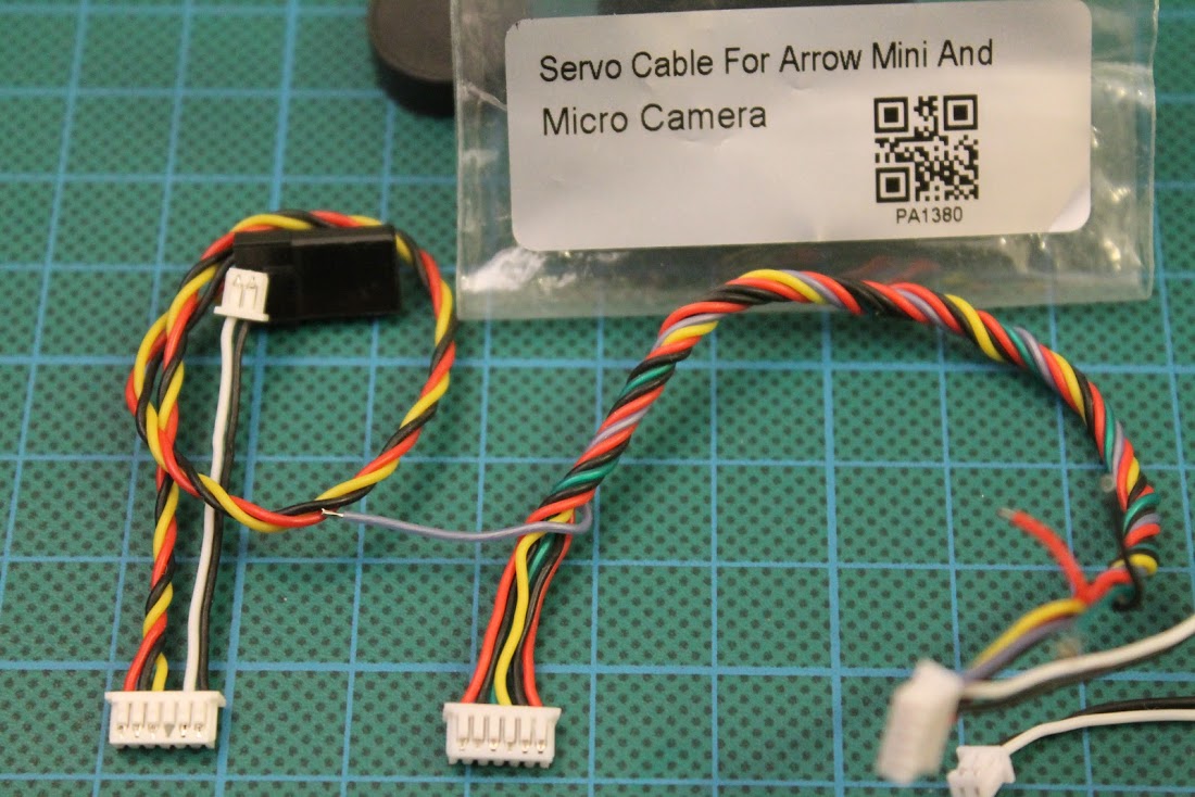
Now you can assemble back the camera and try the audio feed – it should be working. But before continuing – a few words about the cable. The supplied camera cable has 5 wires connected instead of the the total 6. You can either take the missing pin from another similar plug and put it in the missing place or you can use Foxeer Mini and Micro Arrow camera cable it has exactly the same 6 pin connecto that is needed.
![]()
In order to let more sound in I have drilled the 1.5mm hole in the right side of the camera casing.
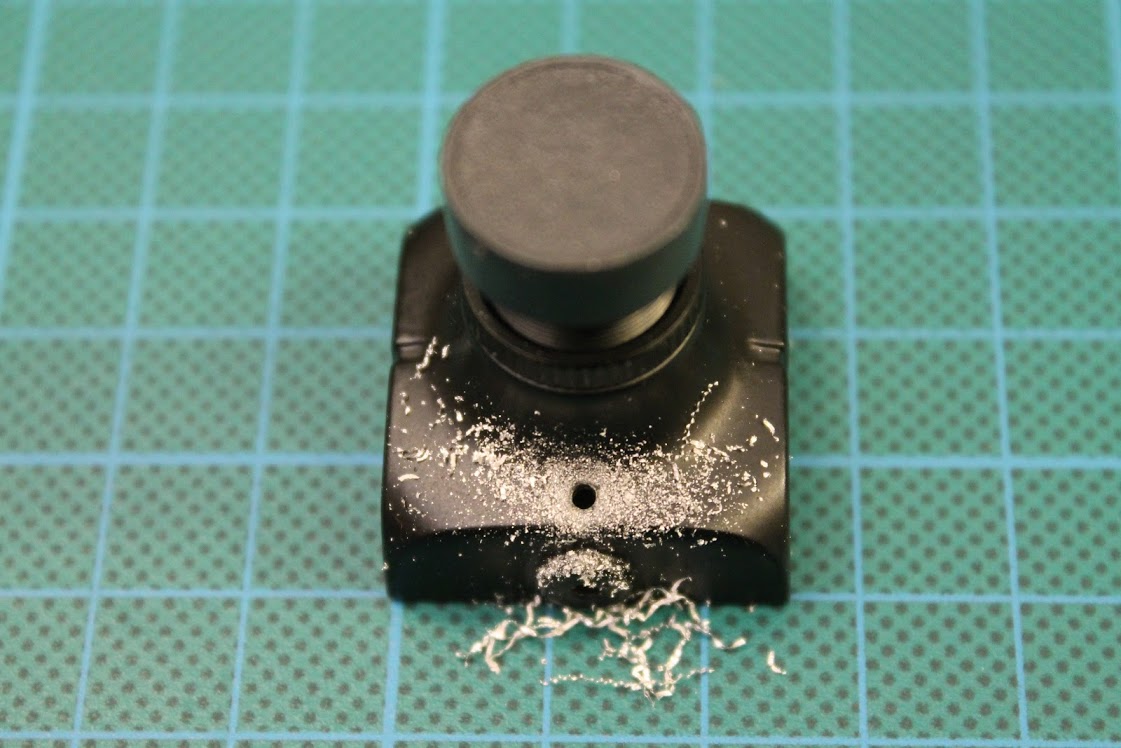
Then glued some foam to cover the hole and to protect the camera sensor from the dust.
You can experiment without drilling the hole. My microphone level came out a bit too high, so probably drilling the hole is not necessary. Try it out!
The example of the sound from modified Foxeer HS1170 V2 can be heared here:
So that is. You can enjoy the sound from your Foxeer HS1177? V2 camera!
Foxeer HS1177 V2? can be purchased @ Surveilzone:?http://ww.surveilzone.com/Foxeer-600TVL-HS1177V2-FPV-CCD-Camera-g-1715
or @ Banggood:?https://www.banggood.com/Foxeer-HS1177-V2-600TVL-CCD-2_5mm2_8mm-PALNTSC-IR-Blocked-Mini-FPV-Camera-5-40V-w-Bracket-p-1148677.html
]]>
Parts list
Frame:?Lantian LT105 frame kit – $6.39
Motors:?Chaoli 8x20mm brushed motors – $12.56. Other options:? Racerstar 8.5x20mm 53500RPM Coreless Motor?– $13.99
FC:?SP Racing F3 brushed flight controller -$10.91
Receiver: iRangeX tiny flysky receiver – $4.13. Other options:? Flysky FS82 AFHDS 2A Receiver?– $7.69, Frsky D8 micro receiver?-$8.69
Battery: Eachine 1S 600mAh 50C – $4.99.?Other options: XF Power 1S 600mAh 30C?– $4.49
Propeller?JJRC JJPRO-T1 propellers (these are copy of Walkera Ladybird props) – $0.92
_________________________
Total cost w/o camera/vtx: $39.90
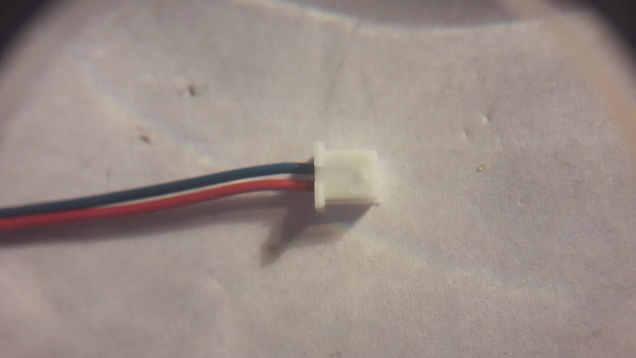
Also I have used 1.25mm mini JST connector sets?(also called PicoBlade or Losi MX connectors) for easy motor plugging and camera power cable, supplied with camera set.
FPV All-in-One camera TX01 NTSC – $20.99 or All-in-One camera TX01 PAL – $20.99 (choose whichever you like most)
Total cost: $60.89
You can get pre-build version of this brushed quadcopter for around $60, but you’ll loose the joy of building and our part list is better – better motors, battery, etc.
Build
Lets take a look at the parts closely. Lantian LT105 frame kit includes: base plate. top plate, rubber grommets, nylon 2mm sized standoffs, nylon 2mm screws, rubber rings and stickers (who knows the right meaning for the M1, M2, M3, M4 ? put a comment below)
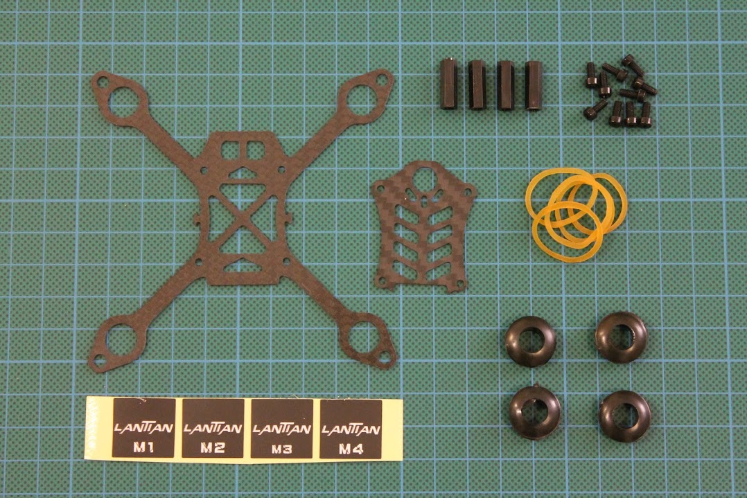
Main frame plate thickness is 1mm. Upper plate is also 1mm thick.
?
?
F3 flight Controller?is equipped with STM32 F3 microcontroller and has powerful FETS for brushed motors. This board even has 3UART(!) ports
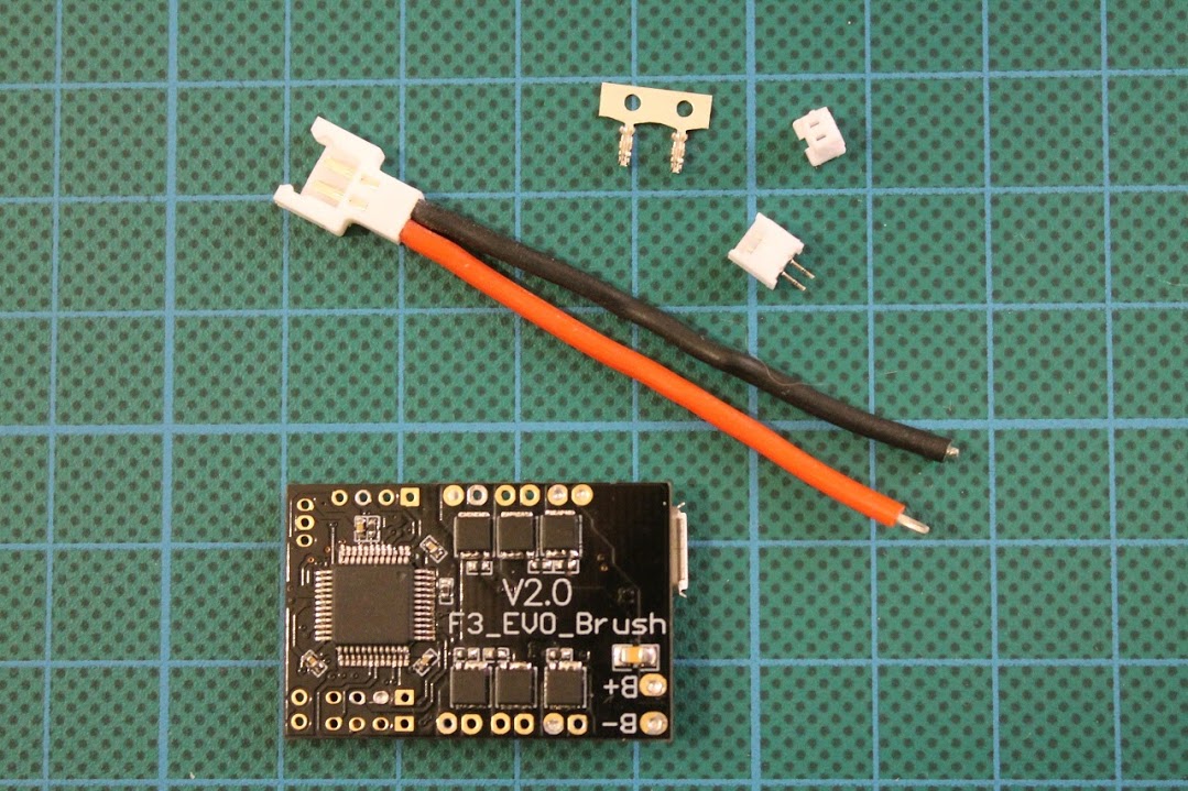
The?power cable, included with flight controller is very thick and not flexible and also wights a lot. I suggest to order this 1to5 micro losi parallel charging cable. You will have 5 pigtails with soft silicone cables that are light and flexible.
2 Clockwise and 2 Counter Clockwise rotation 8.5mmx20mm motors. These motors actualy were bought on eBay for $5.
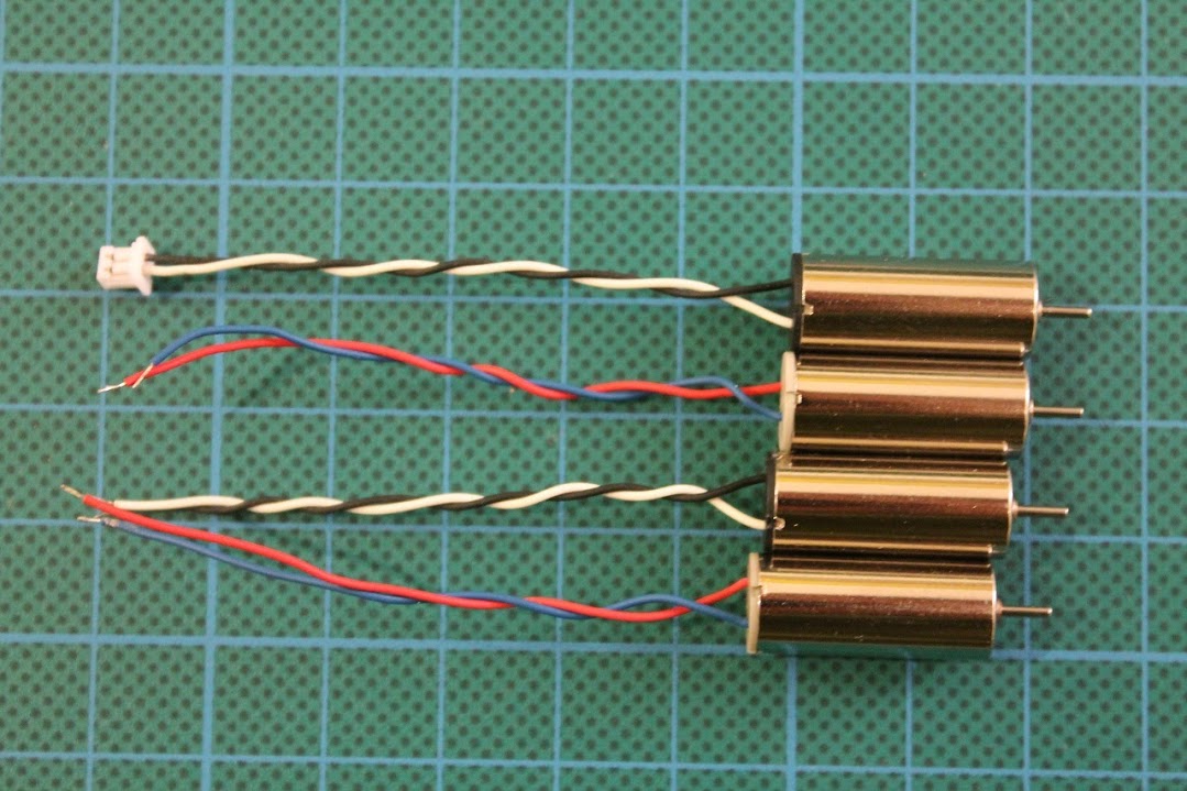
As these motors came with lose wires, I have decided to solder Micro JST 1.25 plugs for easy motor changing on the field. These brushed motors have relatively short lifespan, so you will definitely have one of them broken in the middle of the flight. If your motor is soldered to the FC, then it is really hard to fix it on field, but if it is only a matter of unpluging old one and plugging ne one, then your day will be saved.
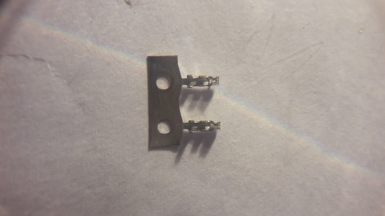
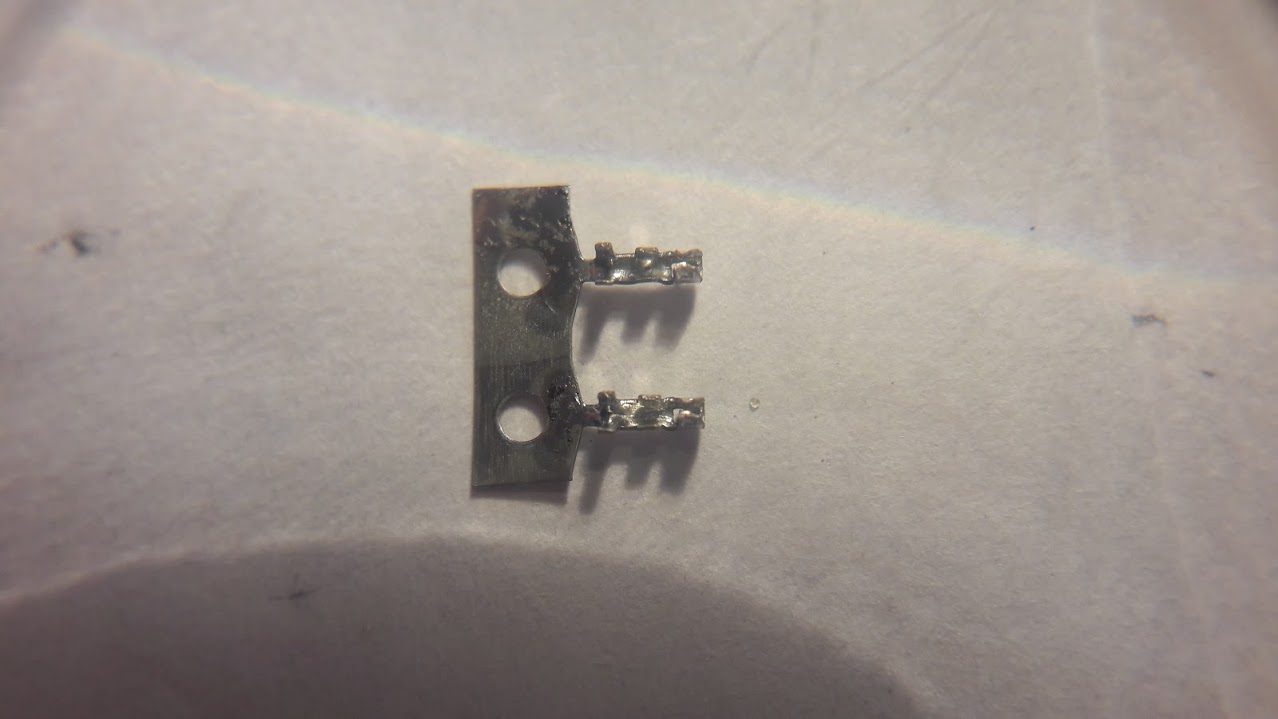
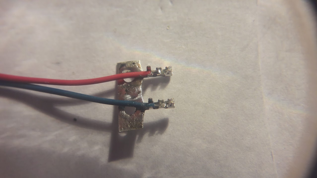
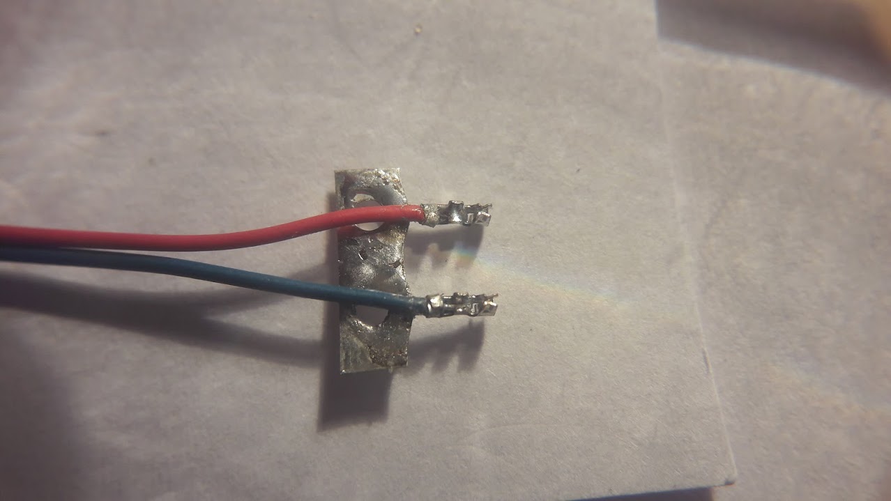
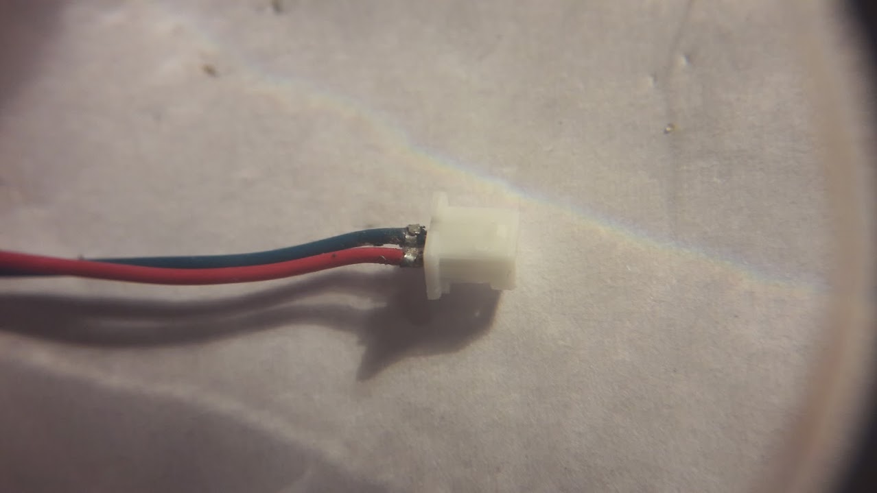
How to solder motor wires to these micro connectors: I aplly very small amount of the solder?with flux to the terminals, then solder stripped pre-tinned motor wires to the terminals. Use small pliers to fixate the wire by two brackets. Insert the soldered terminals into plastic connector and use some tool to push the terminals into the connector.
?
Next part is super small Flysky receiver. This particular receiver is not for sale anymore (for some unknown reasons), but the direct substitute is this iRangeX receiver.
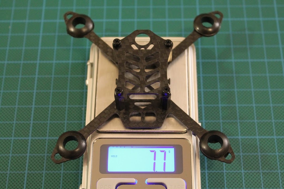
The assembled frame weights only 7.7 grams.
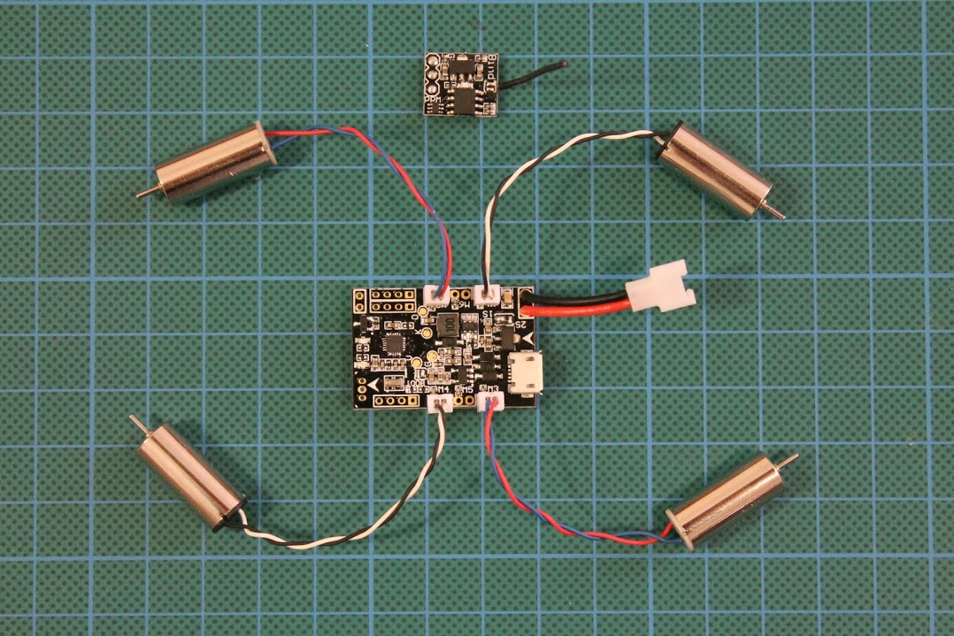
Solder mini-JST sockets to the board, battery cable with micro Losi connector. The right motors configuration shown below.
Attach the fight controller with double sidded tape to the frame.
Oh by the way I have already soldered the FlySky receiver to the FC
Closeup pictures:
Now install the motors into rubber grommets.
The final result (without FPV equipment):
?
[To be continued]
Updated 2017-07-07
?