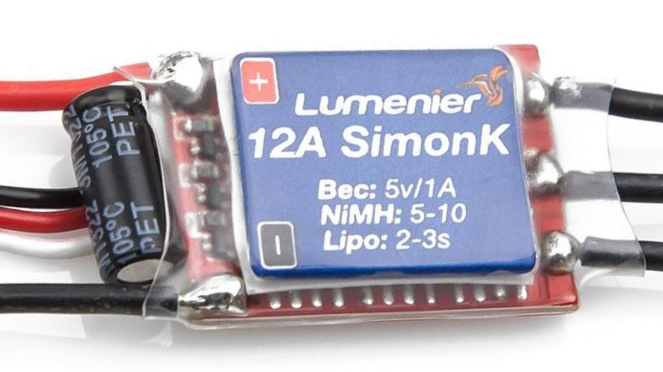
SimonK Firmware (released in 2011)
SimonK firmware was developed by Simon Kirby in the early days of multirotor drones (2011).
It aimed to improve the response time of ESCs compared to the stock firmware.
SimonK’s firmware featured optimizations that reduced delay, allowing for more precise control and smoother motor response.
The firmware was popular among early drone enthusiasts for its performance benefits.
While SimonK was a significant step forward, it had limitations in terms of compatibility and the range of features it offered and its capabilities are now surpassed by more recent firmware.
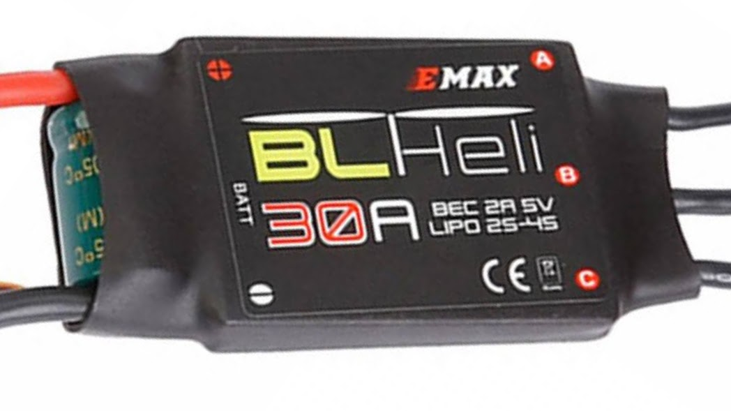
BLHeli Firmware (2013)
BLHeli firmware was created as an evolution of SimonK to address its limitations.
It was developed by the BLHeli open-source project and offered a more extensive feature set.
BLHeli introduced features like Active Braking and improved compatibility with a wider range of ESC hardware.
It became a popular choice for users who wanted more control and customization options for their ESCs.
BLHeli firmware was regularly updated to support new hardware and provide new features.
BLHeli firmware has special configuration program called BLHeli Suite. Read more about the BLHeli Configurator here: BLHeli Suite and BLHeli Configurator How To
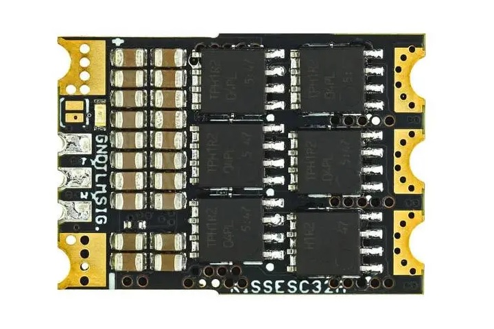
KISS ESC Firmware (2014)
KISS ESCs came with their proprietary firmware, developed by Flyduino. KISS firmware is known for its simplicity and reliability.
KISS firmware is ideal for those who prefer a straightforward and stable option, particularly for racing drones.
KISS firmware is proprietary and closed source. This firmware is mostly popular between KISS enthusiasts. The choice of the KISS enabled hardware is limited. Manufacturers must obtain license from Flyduino.
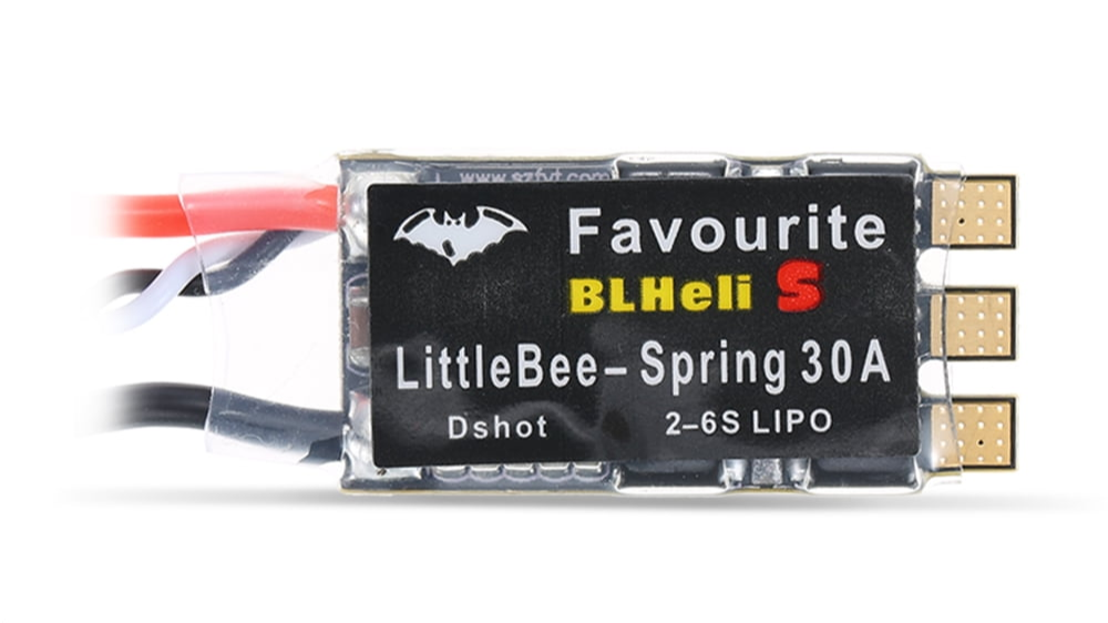
BLHeli_S Firmware (2016)
BLHeli_S, often referred to as simply BLHeli (without the “S”), is an improved version of the original BLHeli firmware.
It introduced significant advancements in terms of performance and support for modern hardware.
BLHeli_S supports DShot communication protocol, offering more precise and faster digital communication between flight controllers and ESCs.
BLHeli_S has been widely adopted in the FPV drone community for its reliability, performance and price. it is the most popular ESC firmware, but is now rapidly replaced by more advanced alternatives like BLHeli_M, BlueJay, and others that support bidirectional DShot.
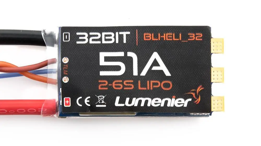
BLHeli_32 (2018)
BLHeli_32 is designed to work with 32-bit microcontrollers, which offer more processing power and capabilities compared to the 8-bit microcontrollers used in previous BLHeli versions. This allows for faster and more precise motor control.
BLHeli_32 fully supports the DShot protocol, which is a digital communication protocol known for its low latency and high precision
BLHeli_32 was the first ESC firmware that introduced bidirectional DShot. This allows for communication in both directions between the flight controller and ESC. This enables telemetry data to be sent from the ESC to the flight controller, providing information about motor RPM, current draw, and other parameters.
BLHeli_32 supports higher DShot baud rates, including DShot1200 or even DShot2400, which offers extremely fast communication.
JESC (2019)
JESC is an ESC firmware created by Joe Lucid for BLHeli_S ESCs. The main firmware advantage over BLHeli_S is ability of sending the RPM telemetry to the FC, enabling the RPM Filtering for reduced motor noise, enhanced performance, and smoother flight characteristics. JESC also supports higher PWM frequencies like 48 kHz providing improved battery life and other benefits.
The JESC firmware is based on the open source project BLHeli_S and is also?open source. To enable dshot RPM Telemetry you need to license the optional Telemetry Service.?Each ESC requires one license. You need to purchase 4 licenses for a 4in1 ESC (price is about $5 for a 4in1 ESC).
In the year 2020 JESC was definitely popular cheaper option for having ESC firmware with RPM Telemetry features. Only BLHeli_32 and JESC had DShot RPM telemetry at the time.
BLHeli_M (JazzMaveric) (2020)
BLHeli_M, often referred to as JazzMaverick or simply “JazzM,” is a specialized firmware based on the BLHeli_S, designed for electronic speed controllers (ESCs) that were compatible with BLHeli_S and is primarily used for micro-sized drones. Unlike BLHeli_S or BLHeli_32, which are widely known and used, BLHeli_M is a less common. BLHeli_M was the first firmware to introduce Bidirectional DSHOT (RPM Telemetry) for free – users could flash the JazzMaveric’s firmware into BLHeli_s ESC and enjoy RPM Filtering something what could be done only with more costly BLHeli_32 hardware before.
JazzMaverick firmware allows users to adjust the PWM frequency to suit their specific needs and flight preferences. This is another key feature that sets it apart from other ESC firmwares.
BLHeli_M firmware was last updated on Sep 28, 2019, so the development is stalled.
Source code repository: https://github.com/JazzMaverick/BLHeli
AM32 (AlkaMotors) (2021)
AM32 is an open-source firmware created by Peter Smith, also known as AlkaMotors, for BLHeli_32 compatible ESCs.
AM32 supports features like firmware upgrades, various ESC protocols, bidirectional communication like the BHeli_32 and efficient motor startup.
It’s compatible with STM32, GDS32, AT32 family MCUs. However it supports only limited number of the ESCs. Some manufacturers are releasing ESCs with AM32 firmware (Skystars, NeutronRC).
BlueJay (2022)
Bluejay is the open source successor to BLHeli_S adding several improvements to ESCs with Busy Bee MCUs (EFM8 BB21 and EFM8 BB51).
BlueJay is built on the base of BLHeli_S firmware version 16.7.
BlueJay firmware supports the DShot digital communication protocol with options for DShot150, DShot300, and DShot600.
One of the standout features of BlueJay is its support for bidirectional DShot, which enables RPM telemetry. This means that the ESCs can communicate motor RPM data back to the flight controller enabling the use of the RPM filtering.
BlueJay allows users to choose between different PWM frequencies, including 24 kHz, 48 kHz, and 96 kHz. This flexibility enables fine-tuning for specific flight characteristics and motor setups.
Other BlueJay features are: PWM dithering with 11-bit effective throttle resolution, startup power and RPM protection, Low commutation interference, smoother throttle to PWM conversion, user configurable startup tunes.
BlueJay Configurator (ESC configurator): https://esc-configurator.com/
Which is the fastest ESC protocol?
Below is the list of the ESC protocols and their main features. You can compare the speed by the packet update Time and Refresh Frequency.
| ESC Protocol | Analog or Digital | One-way or Bi-directional | Packet Update Time (μs) | Refresh Frequency (kHz) |
|---|---|---|---|---|
| PWM | Analog | One-way | 1000-2000 | 0.5 |
| OneShot125 | Analog | One-way | 125 | 8 |
| OneShot42 | Analog | One-way | 42 | 23.8 |
| MultiShot | Analog | One-way | 5-25 | 40 |
| DShot150 | Digital | Bi-directional | 106.7 | 9.4 |
| DShot300 | Digital | Bi-directional | 53.3 | 18.8 |
| DShot600 | Digital | Bi-directional | 26.7 | 37.5 |
| DShot1200 | Digital | Bi-directional | 13.3 | 75 |
| DShot2400 | Digital | Bi-directional | 6.7 | 150 |
With a packet update time of approximately 6.67 μs, DShot2400 is the fastest protocol listed in the table. It offers the quickest communication between the flight controller and the ESCs. However it is specifically supported only by BLHeli_32 ESCs, and it requires both the ESCs and the flight controller to support this high-speed protocol.
DShot was coded in a way that will not use significantly more CPU resources going to higher communication speed. However, when using Bidirectional DShot, the higher the communication speed of the DShot protocol the more the MCU has to process thus increasing the total computational load. Flight controllers with the slower MCUs most probably are unable to support Bidirectional DShot2400 or even Bidirectional DShot1200.
Meantime most BLHeli_32 ESC will work with DShot2400. Only F3 based BLHeli_32 ESC will work with DShot4800
Glossary
DShot Bidirectional Telemetry: DShot Bidirectional Telemetry, often referred to as DShot Telemetry or ESC Telemetry, is a feature that allows the ESCs to send real-time telemetry data to the flight controller. This telemetry data includes information about motor RPM (Revolutions Per Minute), current consumption, voltage, and temperature. The flight controller can then process and display this data on the pilot’s OSD (On-Screen Display) or transmit it to a ground station or remote display device.
Key points about DShot Bidirectional Telemetry:
- RPM Data: One of the primary functions of DShot Telemetry is to provide RPM data for each motor. This telemetry is used primarily for the RPM filtering. This telemetry also allows pilots to monitor motor performance and detect potential issues like propeller strikes, motor damage, or out-of-balance props.
- Current and Voltage Monitoring: ESC telemetry also provides information about current draw and voltage levels, which are crucial for monitoring power consumption and battery health during a flight.
- Temperature Information: Telemetry can also report the temperature of the ESCs, which can help pilots keep an eye on the thermal performance and avoid overheating.
- Display on Flight Controller’s OSD: DShot Telemetry can be read by the flight controller software, allowing for real-time data processing and display. Some flight controllers and OSD systems are more compatible with this feature than others.
RPM Filter: The RPM filter is a feature available in BLHeli_32 firmware and some other firmwares like BLHeli_M, JESC, BlueJay, AM32, that utilizes motor RPM data to enhance filtering and noise reduction in the flight controller’s PID (Proportional-Integral-Derivative) control loop. By using the RPM data from each motor, the RPM filter can isolate and filter out noise generated by the motors, improving flight stability and reducing vibrations. This results in smoother and more precise control of the drone.
Key points about the RPM filter:
- Noise Reduction: The RPM filter helps to eliminate motor-related noise that can affect the drone’s flight performance and, in some cases, lead to instability.
- Improved Flight Characteristics: With less motor noise affecting the control system, the drone can respond more accurately to pilot inputs, making it easier to fly and providing better acrobatic performance.
- Compatibility: The RPM filter is typically used with BLHeli_32 ESCs and flight controllers that support this feature.
Read more about how to set up the RPM filtering here Guide: How to set up the RPM filtering
]]>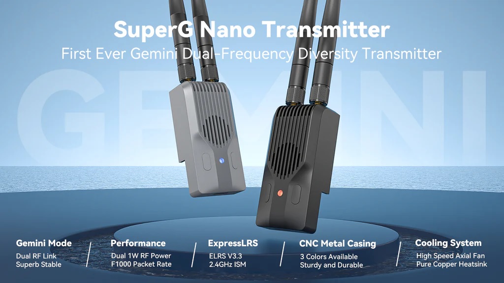
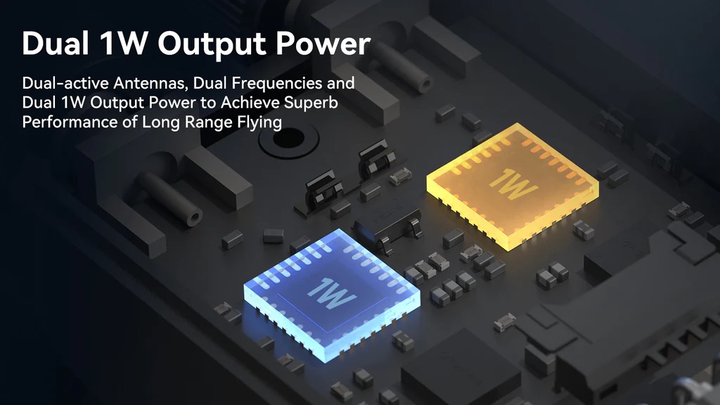
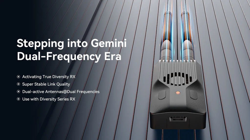
Dual 1W Output Power
BetaFPV SuperG Nano Transmitter has two RF chips, each boasting a powerful 1W transmission power. This power level with a combination of the LoRa radio transmission technology can get you 100Km range and beyond.
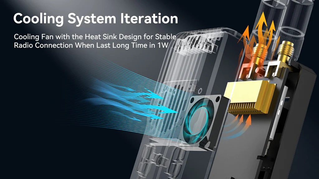
Active cooling system
Transmitter module casing is made of CNC aluminum alloy with efficient thermal conductivity, complemented by heatsink with active cooling fan for optimal heat dissipation.
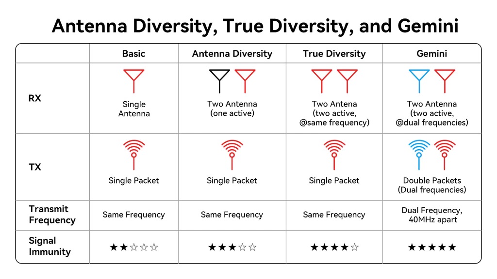
Antenna Diversity, True Diversity and Gemini mode
In the Antenna Diversity mode, two antennas are employed, and they are alternated regularly to assess the RSSI (Received Signal Strength Indicator) value of the signal. This assessment helps determine which antenna should be used for data reception.
In the True Diversity mode, receiver uses two radio chips, each connected to a different antenna. Both antennas receive data on the same frequency simultaneously and the antenna that has the strongest reception at any given time is used.
Meanwhile, in the advanced Gemini mode, two radio chips and two antennas simultaneously receive data with a 40MHz frequency difference. They also transmit telemetry data concurrently but on the different frequencies. This unique approach allows the reception of identical data packets on distinct frequencies and antennas. Gemini mode excels in maintaining stable flight, even in complex radio environments.
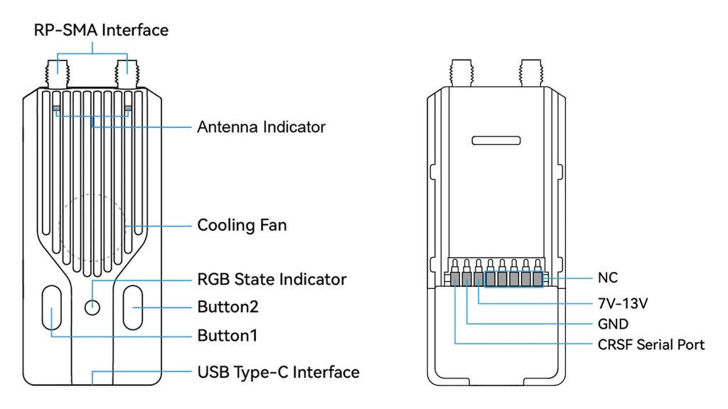
BetaFPV SuperG Dual Diversity Transmitter offers two customizable buttons and a USB Type-C port for . RGB LED for TX status display and 2 LEDs for each antenna status display.
Custom Buttons
BetaFPV SuperG Nano Transmitter reserves 2 buttons that can be customized by users. Here are the specific steps to operate:
- Enable the transmitter’s WiFi or power it on and wait for 60 seconds to enter WiFi mode using LUA programming.
- The RGB indicator light will slowly flash in green, indicating that the transmitter has automatically enabled WiFi (WiFi name: ExpressLRS TX, WiFi password: expresslrs).
- Connect your smartphone or computer to the WiFi network and open a web browser. Enter http://10.0.0.1 to access the custom button settings page.
- In the corresponding button’s Action column, select the desired custom function. Then, choose the button type and the number of presses or duration in the Press and Count columns. Click SAVE to complete the settings.
Currently, there are 6 available functions that can be assigned to shortcut buttons. There are 2 ways to use the buttons: long-press and short-press. The duration of a long press can be customized, while the number of presses for a short press can also be customized. The following are the 6 functions that can be set:?
| Unused | VTX Setting |
| Increase Output Power | Enable WiFi |
| Enter VTX Channel | Enter Binding Mode |
| Enter VTX Band |
The pictures below show the functionality of the transmitter in its factory default settings. (The left button is Button1 and the right button is Button2).
| Button | Action | Press | Count |
| Button1 (Left Button) | Enter Binding Mode | Short Press | 3?Times |
| Increase?Power | Long?Press | For?0.5?seconds | |
| Button2 (Right Button) | Go to VTX Channel Menu | Short Press | 2?Times |
| Send?VTX?Settings | Long?Press | For?0.5?seconds |
BetaFPV ELRS TX modules comparison table
| SuperG Nano TX | Nano TX | Micro TX | |
| Max RF Power | Dual–1000mW | 500mW | 500mW/1000mW |
| RF Chip | Dual SX128x | Single SX128x | Single SX128x |
| Antenna Mode | Gemini | Single | Single |
| Cooling System | Yes | No | Yes |
| Backpack | Yes | No | Yes |
| External Power Supply | Yes, 7-13V | No | Yes, 5-12V |
Power consumption and external power
When the dual transmit power exceeds 500mW, the BetaFPV SuperG Nano Transmitter exhibits relatively high power consumption, leading to a reduced battery life. To prolong the transmitter’s usage time, it is advisable to utilize an external battery as a power source.
The power consumption of the transmitter is not only related to the transmit power but also to the telemetry ratio. When using high power of 500mW and above, the return ratio can be set higher to reduce power consumption and extend use time.
For example, in Gemini mode, the power consumption of setting the return ratio to 1:128 is 1000mA, while the power consumption of setting the return ratio to 1:2 is only half of 1:128.
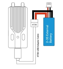
Note: When the voltage of the radio transmitter battery or external battery is lower than 7V (2S) or 10.5V (3S), please use the Gemini mode of 500mW and 1W carefully, otherwise the transmitter will enter the restart state due to insufficient power supply, resulting in disconnection out of control.
Specifications: For those who appreciate the technical details, here are some key specifications of the SuperG Nano Transmitter:
- Antenna Connector: 2* RP-SMA
- RF Power: 25mw/50mW/100mW/250mW/500mW/1000mW
- Packet Rate: 50Hz/100Hz/150Hz/250Hz/333Hz/500Hz/D250/D500/F500/F1000
- Frequency Band: 2.4GHz ISM
- Input Voltage: 7V~13V DC
- Rated Current: 8V, 1000mA @ 1000mW, 1:128, Gemini mode
- USB Port: Type-C
- Fan Voltage: 5V
- Default Firmware Version: ExpressLRS V3.3.0
- Color Options: Black, Red, Grey
- Weight: 44.8g
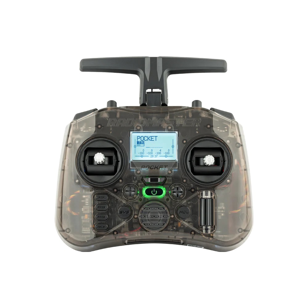
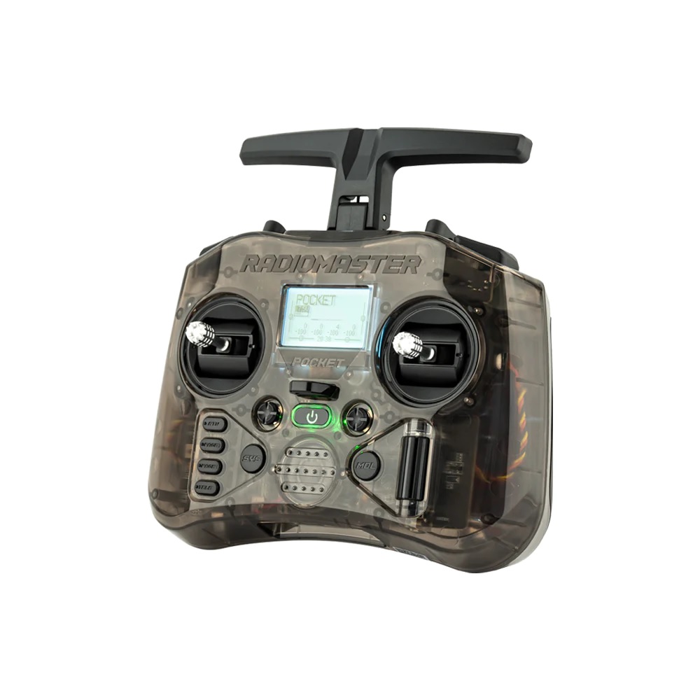

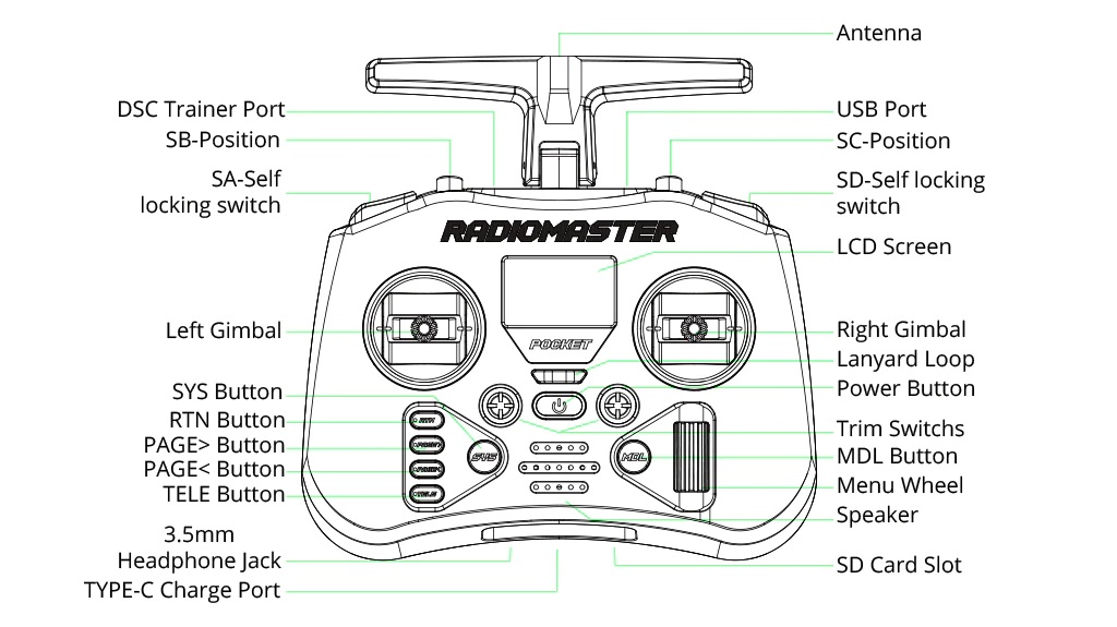
The Radiomaster Pocket Radio boasts a pocket-sized form factor, making it highly portable and easy to carry around. The 128×64 LCD display provides enough information, while the rubberized grips ensure a comfortable and secure hold. The inclusion of a lanyard strap hook allows users to keep the radio close at hand during the flying sessions.
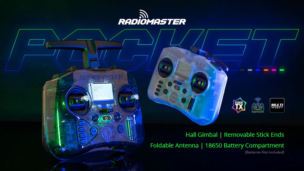
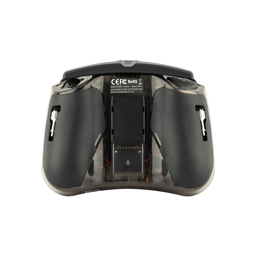
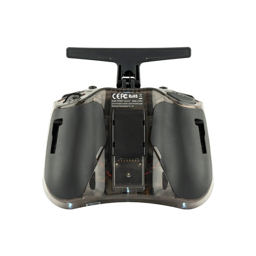
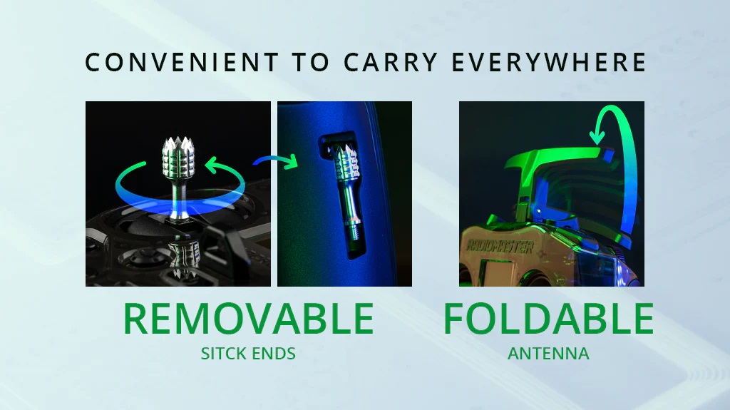
The two hall effect gimbals with removable stick ends provide precise control, and users can conveniently store the stick ends in special slots on the radio’s sides. Additionally, the removable antenna makes it easy to transport and store.
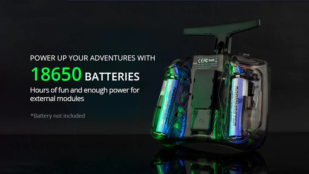
Powered by two 18650 lion batteries, the Radiomaster Pocket Radio offers hours of uninterrupted flying sessions. The USB-C charging port simplifies the recharging process.
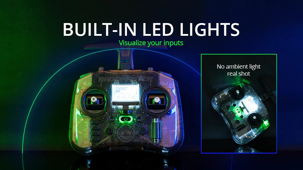
The built-in LEDs offer a simple yet effective way to visualize switch positions.
The RadioMaster Pocket Radio is available in two versions: the CC2500 Version and the ELRS (ExpressLRS) Version. The CC2500 supports a wide range of protocols, including popular ones like FrSky and Futaba. On the other option, the ELRS Version comes with internal ExpressLRS 2.4GHz TX module, delivering 250mW of maximum power. Both versions are equipped with the EdgeTX firmware.
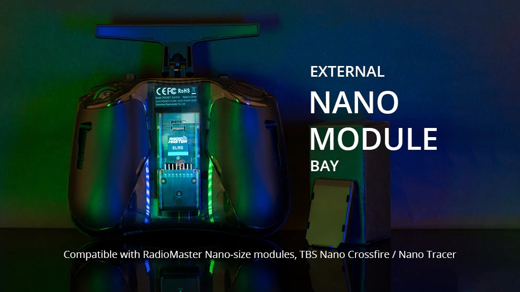
With the inclusion of a nano-sized external module bay, the Radiomaster Pocket Radio enables the use of various external modules.
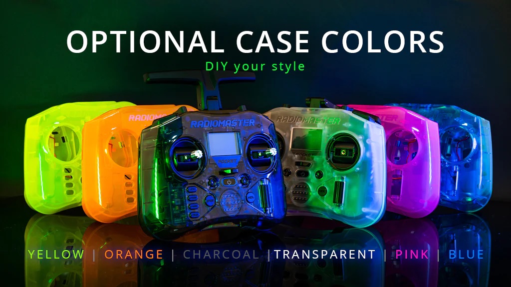
The RadioMaster Pocket is available in two color options, Charcoal and Transparent White. Furthermore, users have the option to choose from a selection of other colors to match their personal style and preferences.
Radiomaster Pocket Radio User Manual: No user manual yet.
Available @
Radiomaster: https://www.radiomasterrc.com/products/pocket-radio-controller-m2
Banggood: https://www.banggood.com/RadioMaster-Pocket-…-Radio-Controller
Specifications
Item: Pocket Radio
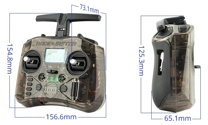
Physical dimensions: 156.665.1125.3mm (Folded size) /156.673.1154.8mm (Unfold size)
Weight: 288 grams
Operating frequency: 2.400GHz-2.480GHz
Internal RF Options: CC2500 multi-protocol / ELRS 2.4GHz
Supported protocols: Module dependent
RF power: CC2500:100mW Max (20dBm) / ELRS FCC: 250mW Max (24dBm) / ELRS EU-LBT: 100mW Max (20dBm)
Operational voltage: 6.6-8.4v DC
Control distance: > 2km @ 20dBm
Operating system: EdgeTX
Control channels: Maximum 16 (Receiver dependent)
Display: 128*64 Monochrome LCD
Battery: 2pcs 18650 batteries (Not included)
Charging: Built in USB-C QC3 Charging
Upgradable Firmware: Via USB or the included SD card
Gimbal: Hall-effect
Module bay: Nano size (Compatible with RadioMaster Nano-size modules, TBS Nano Crossfire / Nano Tracer )
Specifications
MCU: STM32F722
Gyroscope: Bosch BMI270
Input voltage: 3-6S Lipo
Serial ports: 5 UARTS
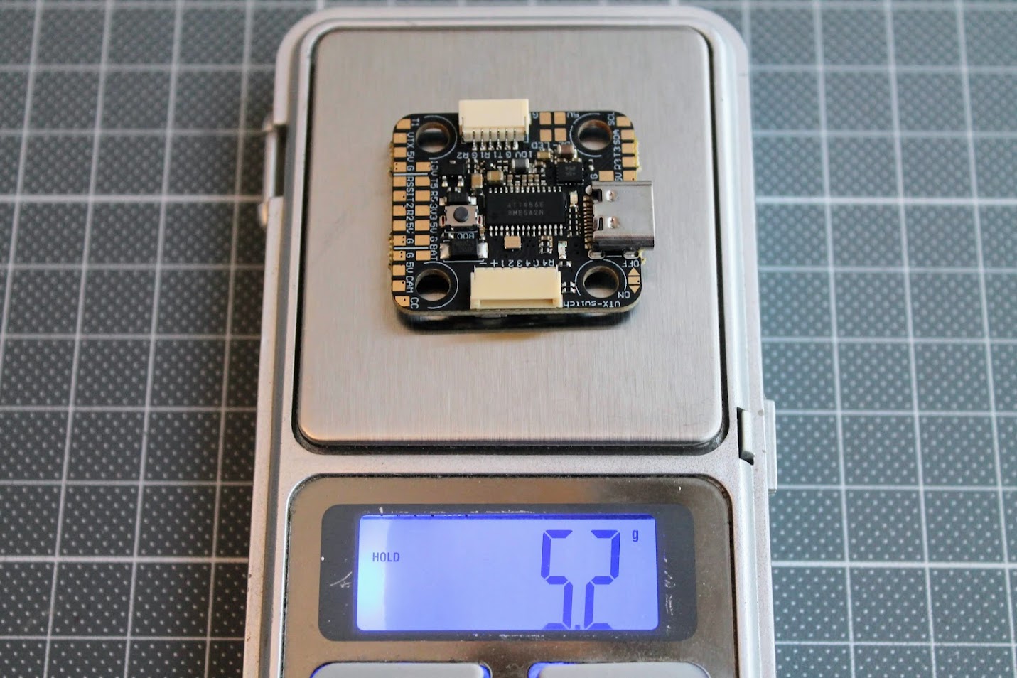
Weight: 5.2 grams
Mount size: 20x20mm
BECs: Integrated 5V/2A and 10V/2A dual BEC
Black Box: 16MB onboard storage
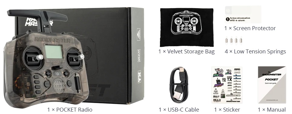
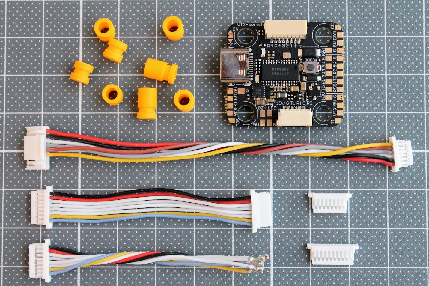
Package Contents
Inside the MEPS SZ F7 Mini FC package, you’ll find the Flight Controller itself along with two size silicone rubber grommets, a DJI Air unit compatible cable, an ESC cable, and a DIY ESC cable with custom connectors on the other end, offering compatibility with nearly any ESC available in the market.
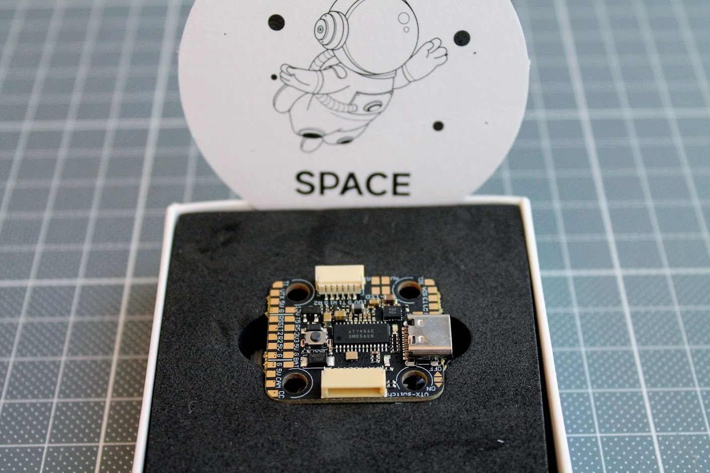
Closer look
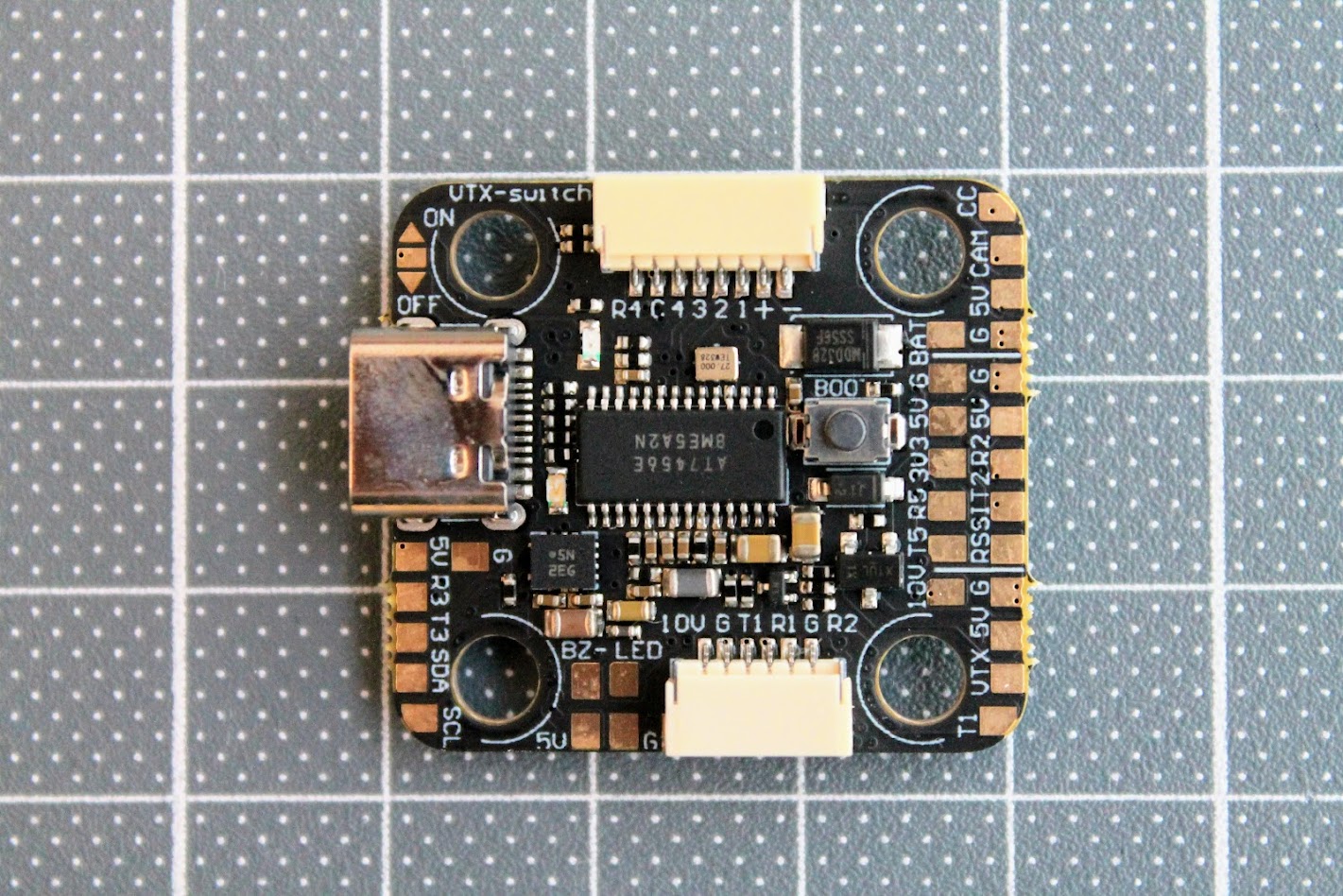
All the connectors and the soldering pads are located on the top side of the board.
On the bottom side of the board you can see the MCU, black box chip and three BEC’s.
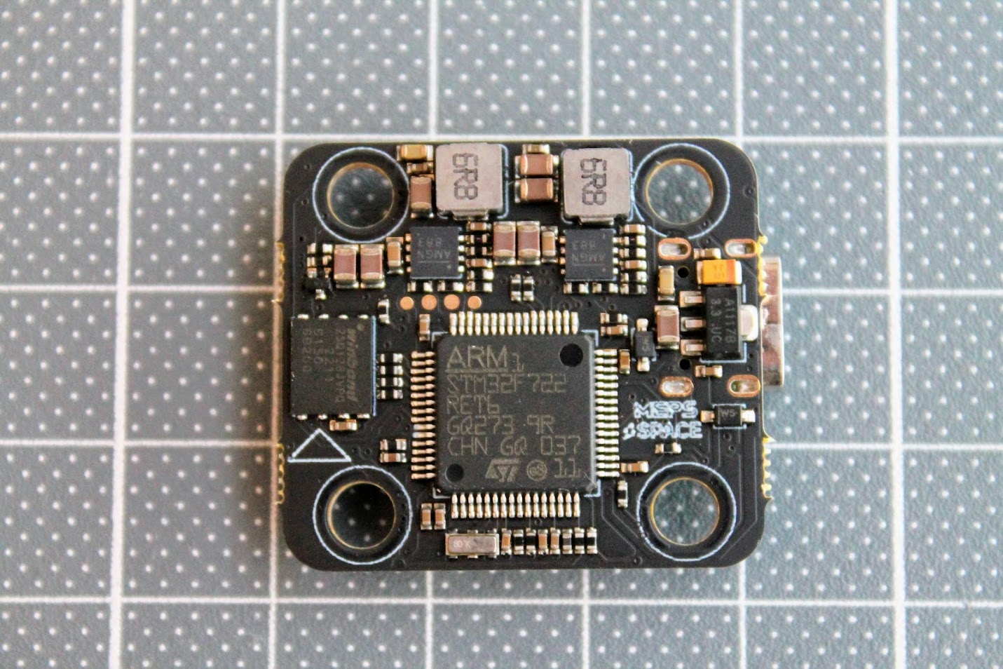
The layout and the components remind me of something… more about it – read further.
The FC board features a VTX switch, allowing users to turn off and on analog image transmission with a single button on the remote control while the drone is on the ground or on the bench. This prevents overheating when the drone is stationary and lacks air cooling.
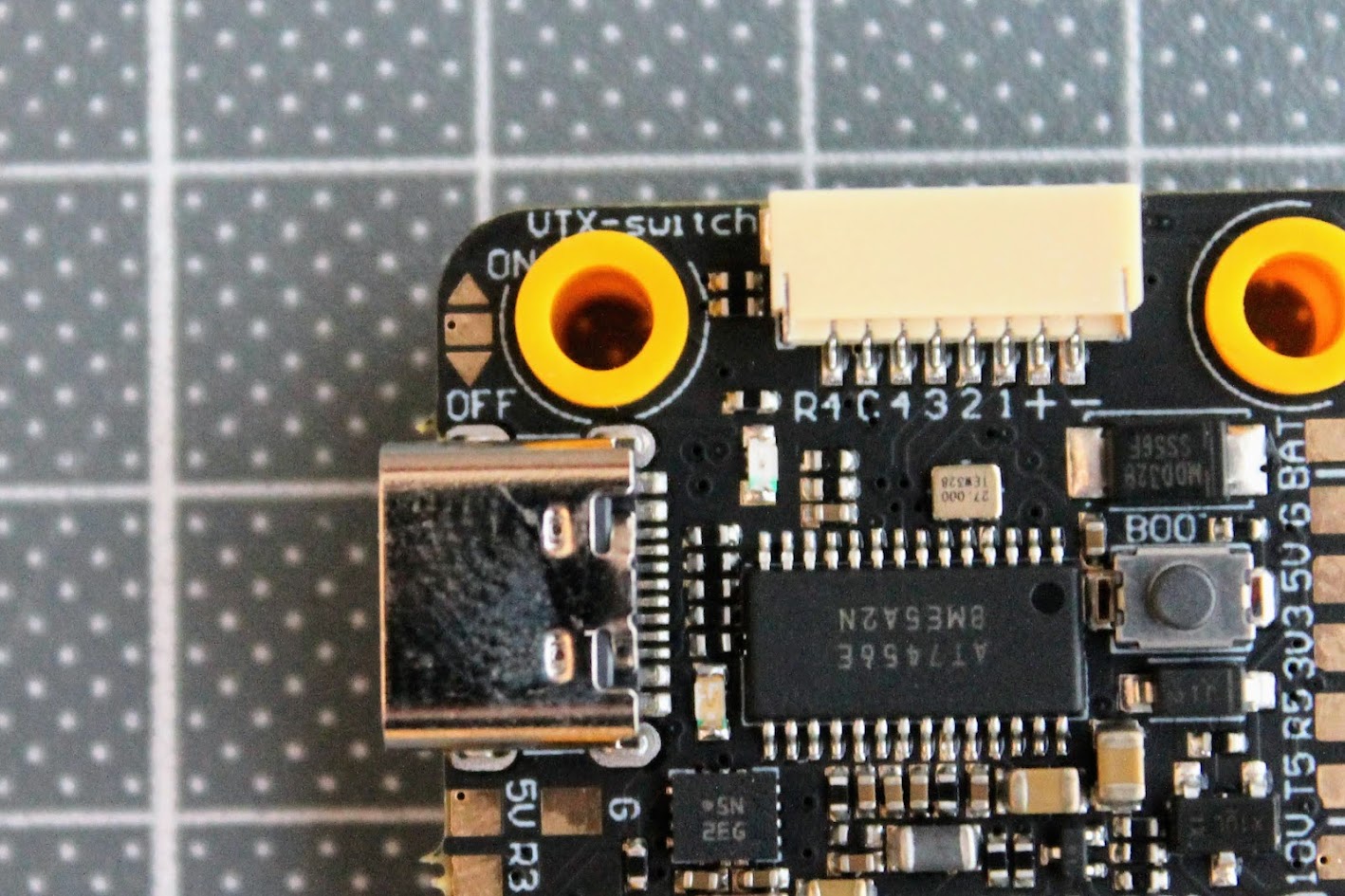
The board incorporates convenient solder pads for effortless connection of GPS with a compass. The pads for RX3\TX3 and SDA\SCL are placed nearby, simplifying the process of connecting peripherals.
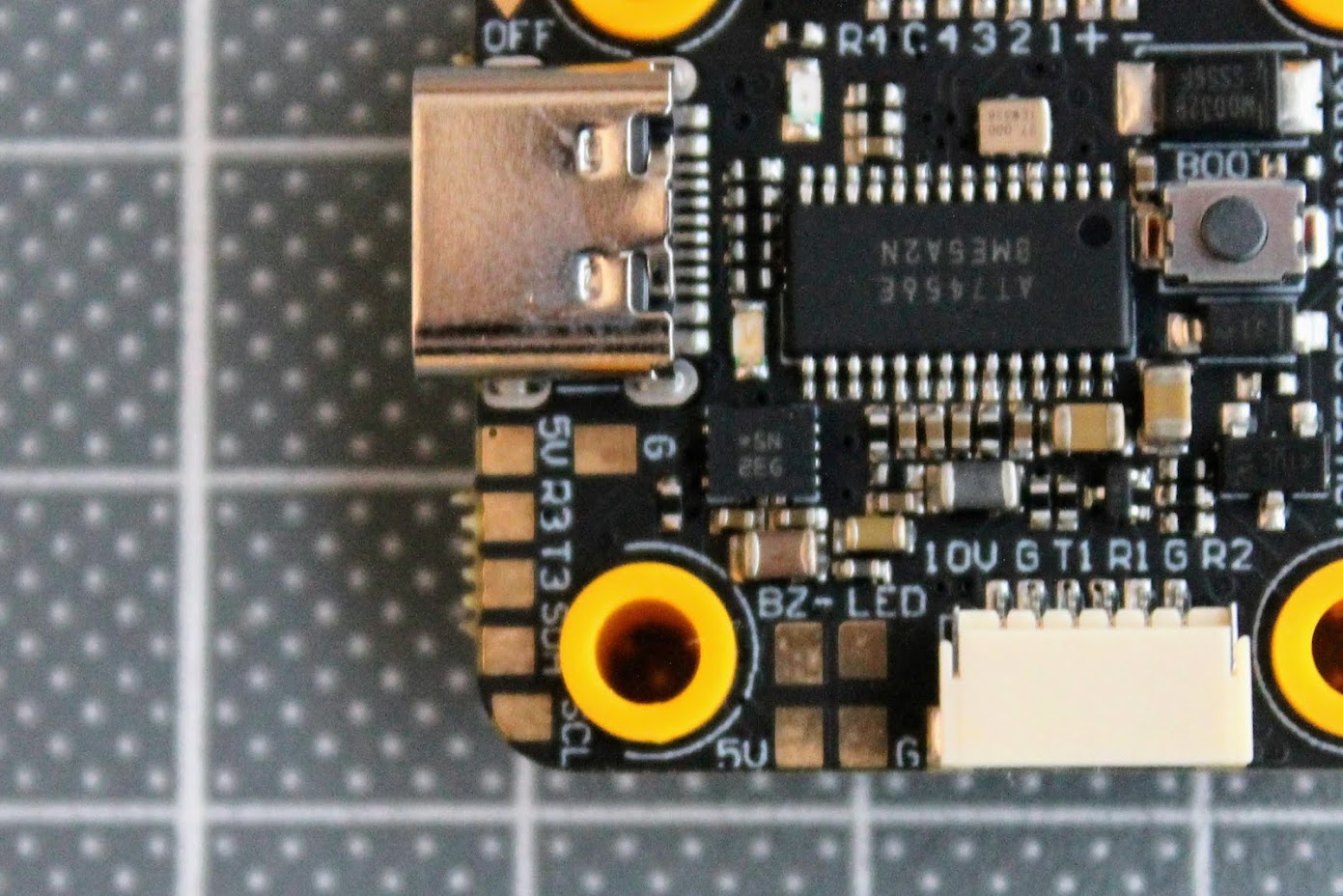
MEPS SZ F7 Mini FC boasts numerous solder pads on the top right side, including pads for VTX – TX1 for SmartAudio connection, 10V and 5V pads for powering the VTX, pads for the camera – CC for camera control, and the option to power the camera directly from the battery using 5V or BAT pads. Additionally, TX2\RX2 and TX3\RX3 ports provide versatility for connecting various radio receivers or peripherals.
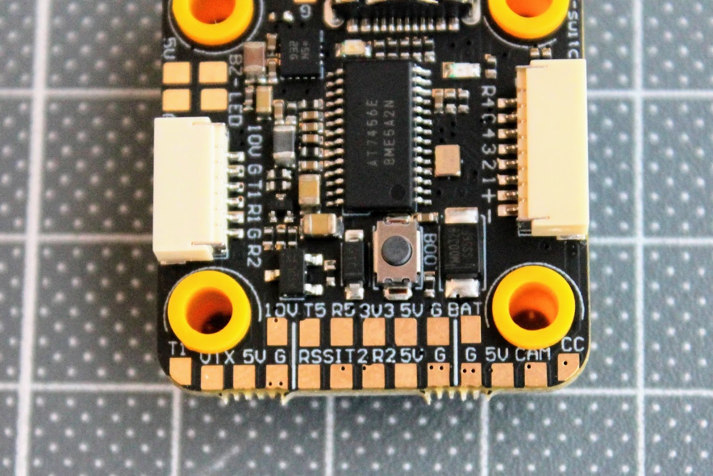
The well-positioned ports for cables further enhance the ease of installation, ensuring a hassle-free setup process for users. The top connector goes to the ESC and the bottom goes to the digital VTX.
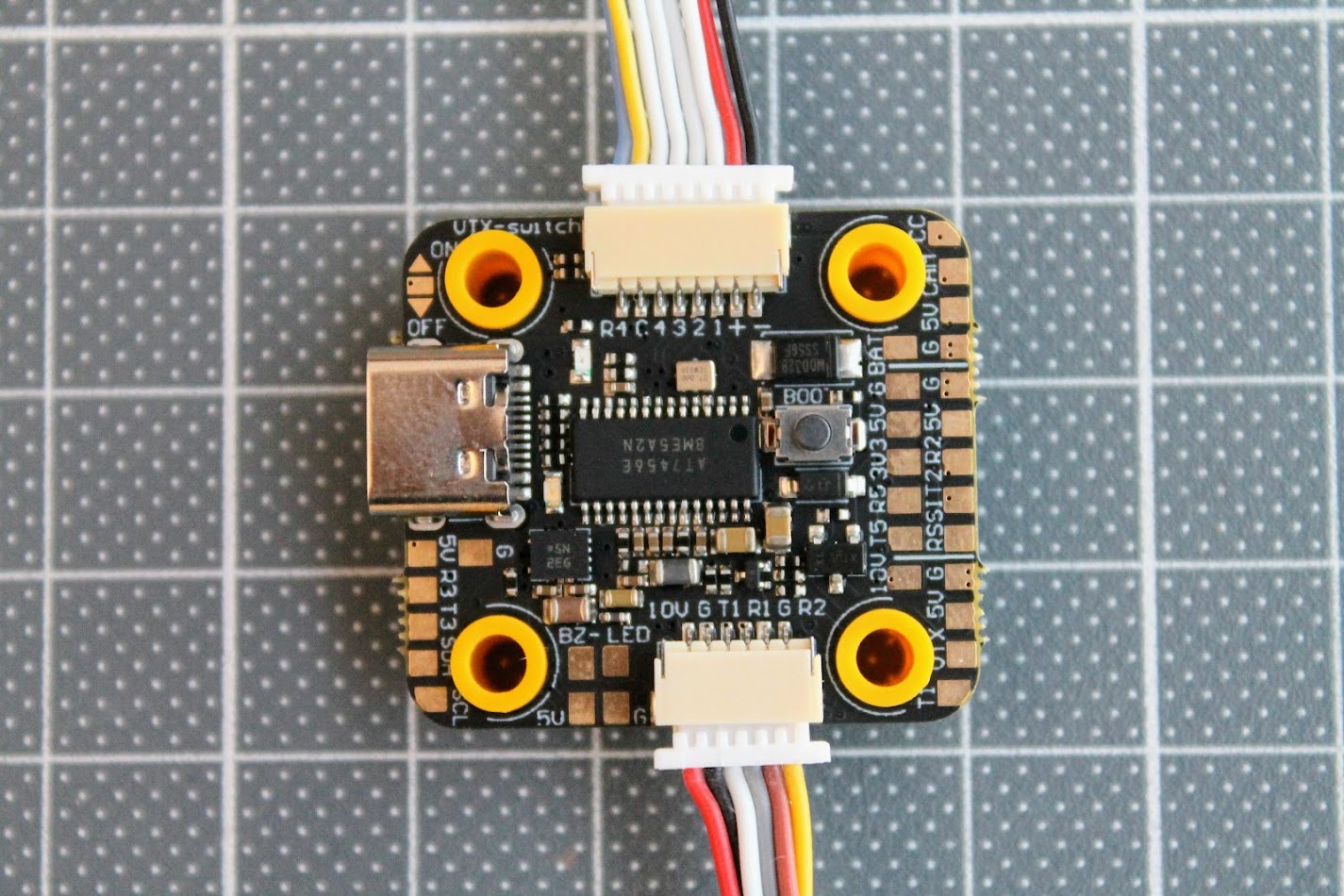
Weighing in at just 5.2 grams, the MEPS SZ F7 Mini FC is lightweight, being about 2 grams lighter than full-size 30.5×30.5mm FCs.
Connection diagrams
MEPS SZ F7 Mini FC Pinout


Connecting the DJI Air Unit to MEPS SZ F7 Mini
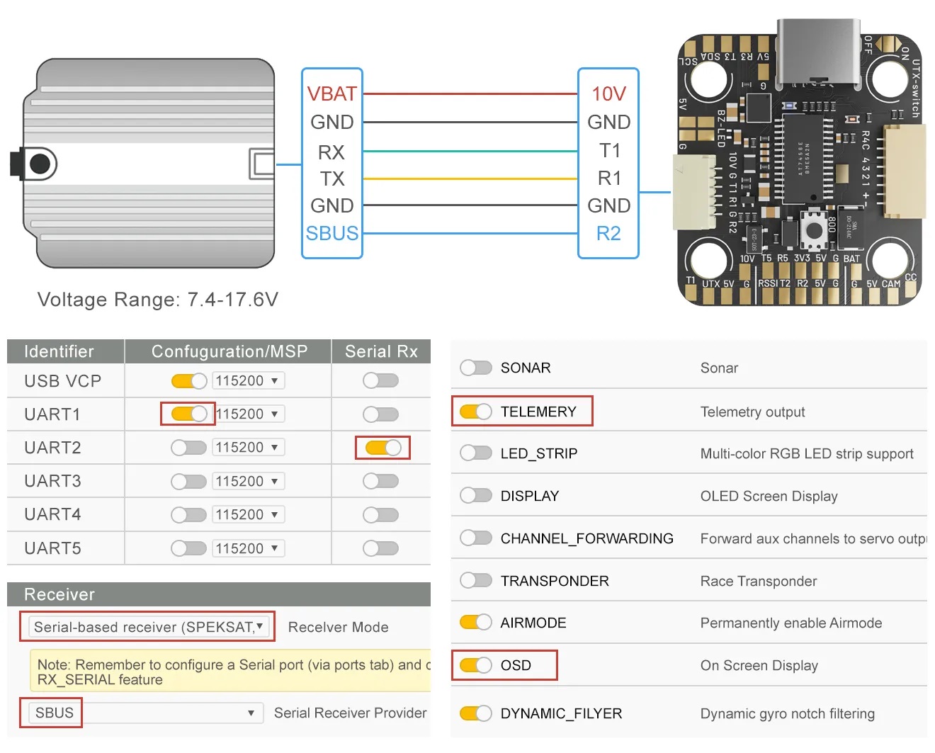
Connecting the Receiver to MEPS SZ F7 Mini
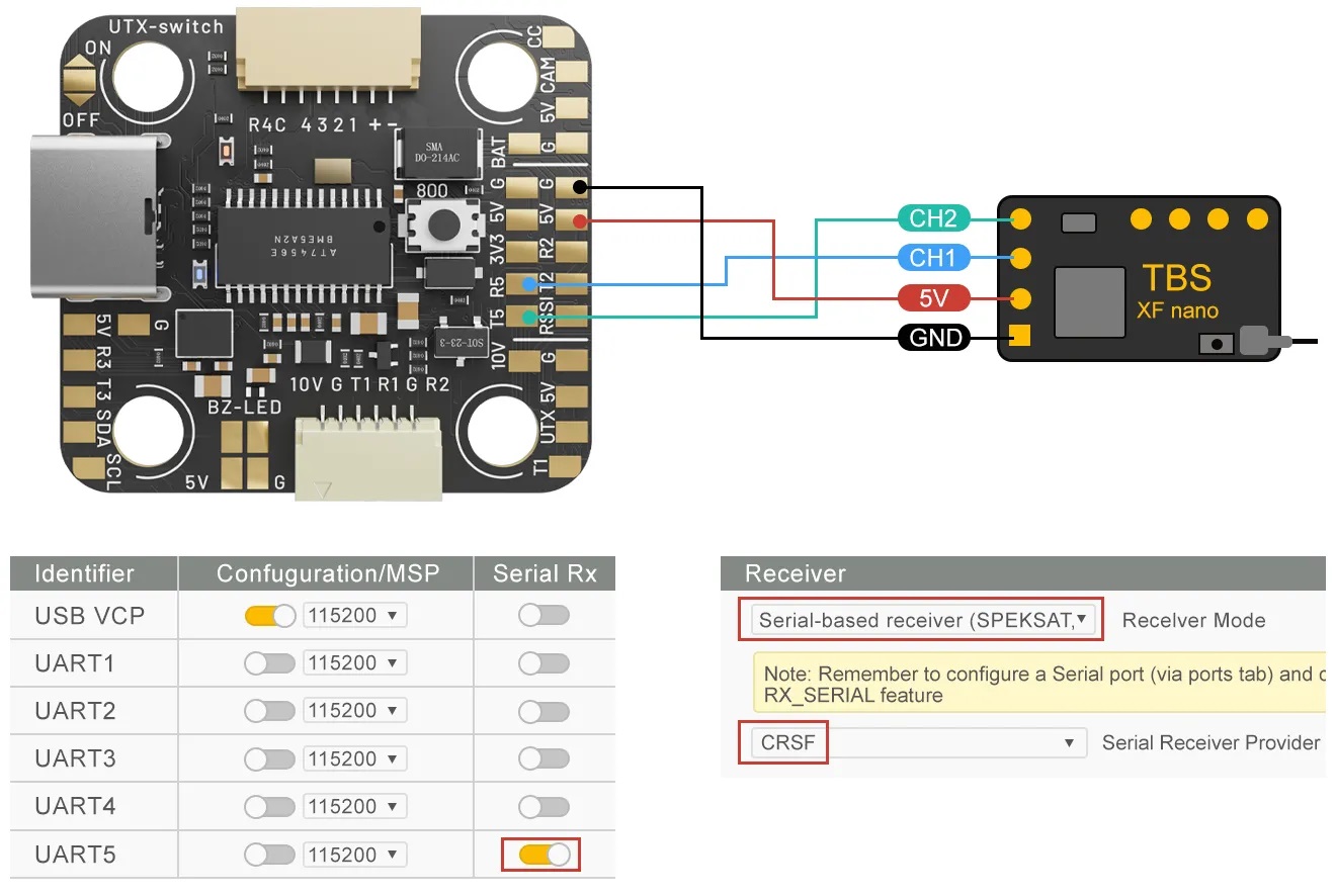
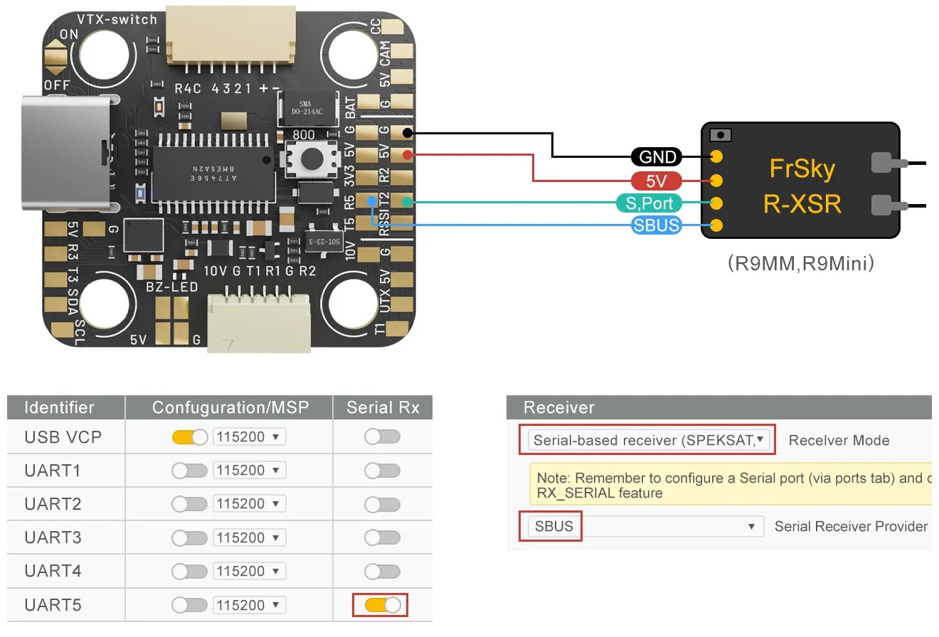
MEPS SZ F7 Mini Flight Controller CLI DUMP and DIFF files:
https://drive.google.com/drive/folders/15y3s0JuZ8RgKm97cAY43_lRKNvBWAtMb?usp=sharing
Conclusions, wrap-up
In conclusion, the MEPS SZ F7 Mini Flight Controller presents itself as a suitable option for smaller quadcopters and racing setups due to its compact size and lightweight design. The use of the powerful STM32F722 MCU and the already proven to be reliable Bosch BMI270 gyroscope ensures stable performance and precise flight control.
With a black box featuring 16MB of onboard storage, this flight controller enables users to record and store flight data for further analysis.
The presence of a VTX switch allows convenient control of analog image transmission, preventing overheating during ground or bench operations.
One notable observation is the striking similarities between the MEPS SZ F7 Mini FC and the T-MOTOR F7 Mini flight controller. The shared features, such as the gyro, black box, VTX pit switch, and dual BECs, along with the remarkably similar layout, couldn’t go unnoticed. It raised questions regarding the relationship between MEPS and T-MOTOR. Whether T-MOTOR produces the FCs for MEPS or if MEPS drew inspiration from the T-MOTOR design remains unclear.
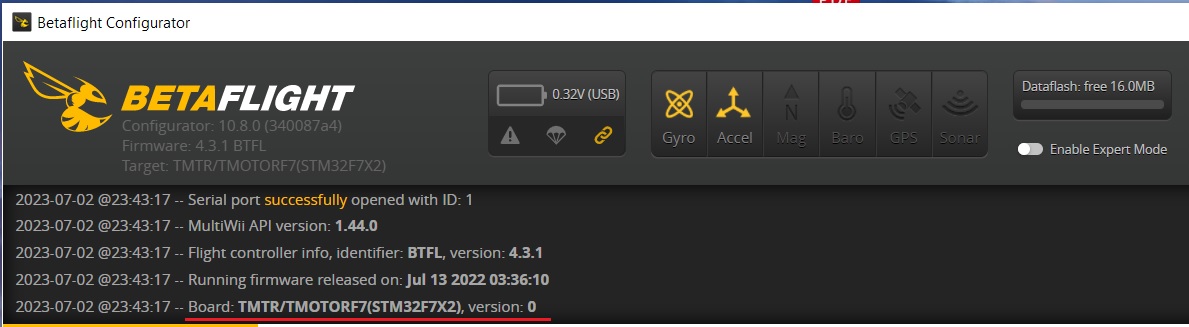
Additionally, upon connecting the MEPS SZ F7 Mini to the Betaflight Configurator, it became evident that the FC is based on the T-MOTOR F7 Mini – firmware target appeared to be the TMOTORF7. This fact further adds to the intrigue surrounding the origins and collaboration between the two manufacturers.
While the MEPS SZ F7 Mini Flight Controller offers notable performance and features, the similarities with the T-MOTOR counterpart raise questions about originality and innovation. Further clarification regarding the relationship between MEPS and T-MOTOR would be beneficial to understand the design choices and potential collaborations.
MEPS SZ F7 Mini Flight Controller can be purchased from MEPS: https://www.mepsking.com/f7-mini-fpv-flight-controller.html
Disclaimer: This item was supplied by MEPS (Mepsking) for a fair and unbiased review. MEPS never asked for a positive review and never influenced my opinion in any way. I’m trying my best to stay uninfluenced and give only my own opinion. All affiliate links if there are any help me purchase items for future reviews and tests.
]]>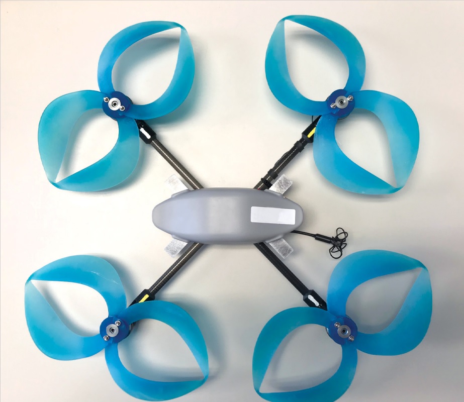
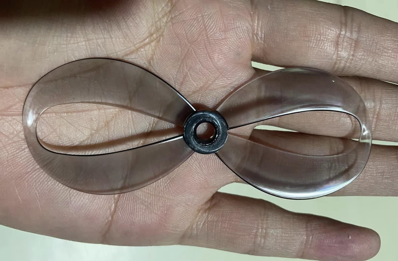
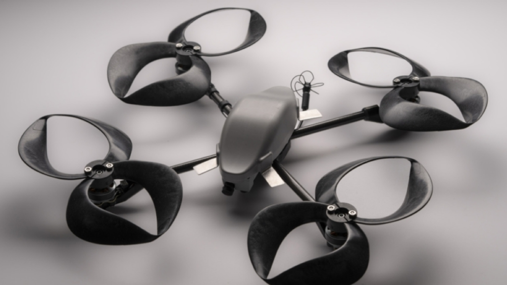
The MIT Solution – the toroidal propeller consists of two blades looping together so that the tip of one blade curves back into the other. This closed-form structure minimizes the drag effects of swirling air tunnels (i.e., vortices) created at the tips of blades and strengthens the overall stiffness of the propeller. These features reduce the propeller’s acoustic signature.
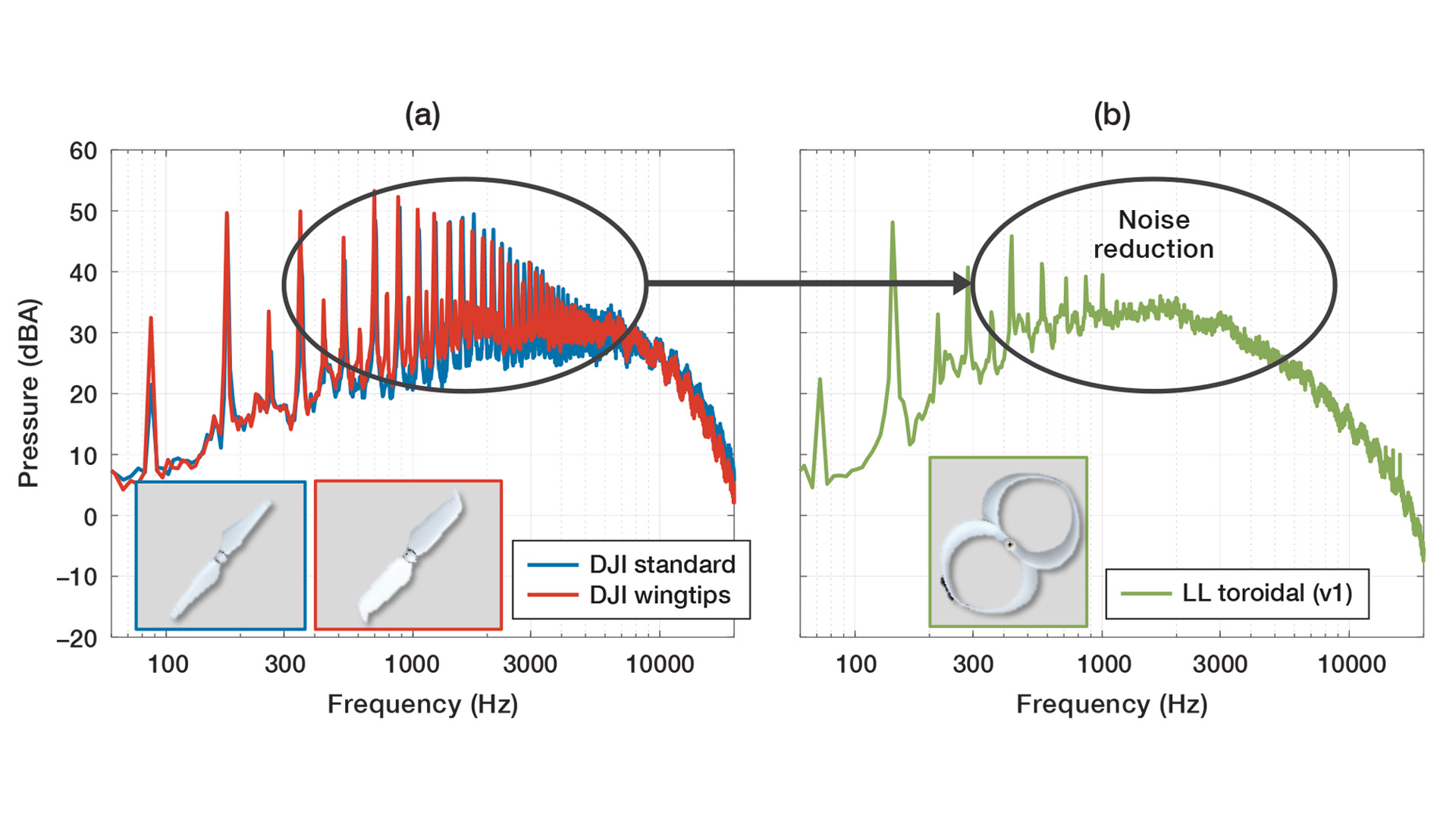
shows the significant reduction of discernible noise achieved by the toroidal propeller.
However, while the toroidal propellers may be quieter, there are questions about their efficiency. The MIT team notes that toroidal propeller achieves thrust “comparable” to that of a multirotor drone propeller, but the community is debating whether this design could potentially reduce the propeller’s thrust and increase drag, which could impact its overall efficiency. Further testing will be needed to determine the tradeoffs between noise reduction and efficiency for this innovative new design.
Gemfan and HQProps are already working on their toroidal propeller design. They are currently in the testing phase of their implementations.

Overall, the toroidal propeller design represents an exciting new development in the field of propeller design and has the potential to be a game-changer for certain applications where noise reduction is a top priority.
If you would like to read more about these new toroidal propellers, check out the original original publication from the researchers at MIT.
]]>
Closer look
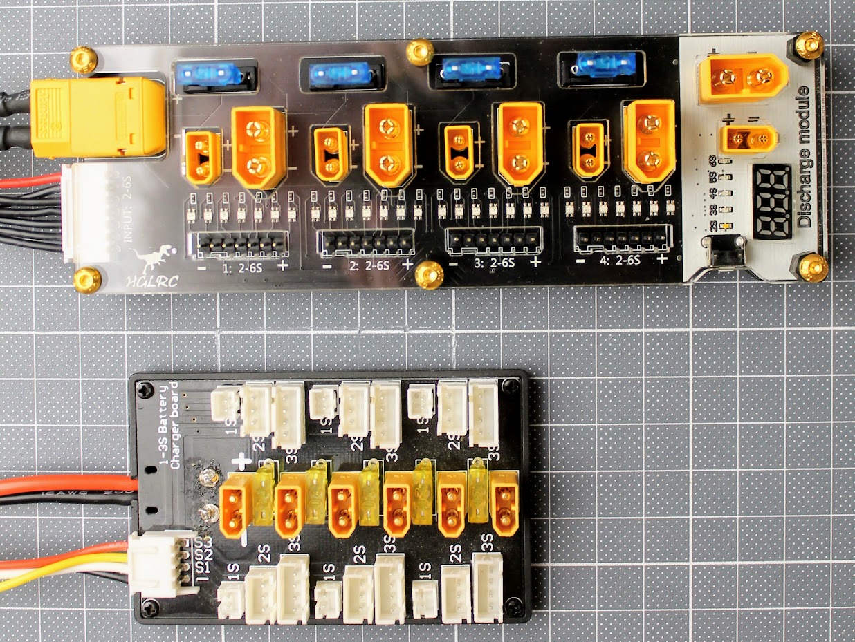
Inside the box you’ll find the HGLRC Thor Pro charger board, XT60 and 6S balance lead connection to charger cables and instruction manual.
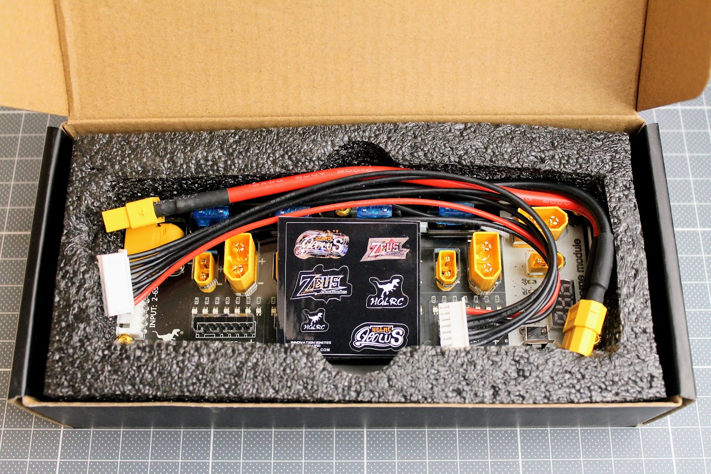
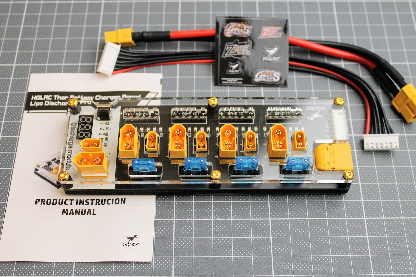
HGLRC Thor Pro charger board can charge 4 batteries in parallel with up to 40A of combined current.
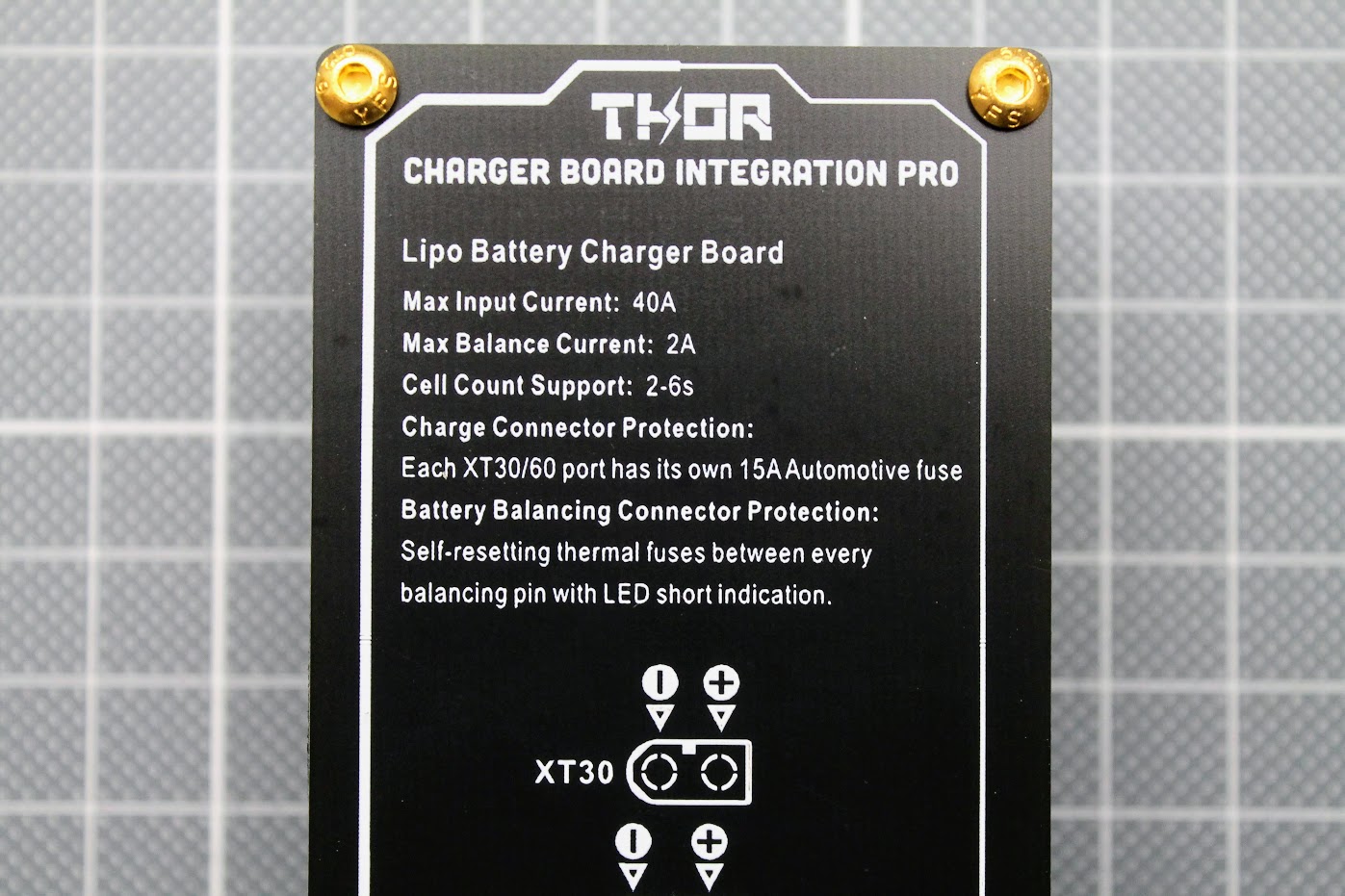
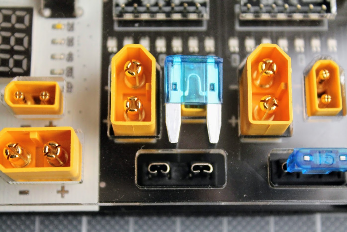
Charger board has 15A automotive fuses for protecting the batteries from short circuit. These fuses have dedicated slots and are replaceable.
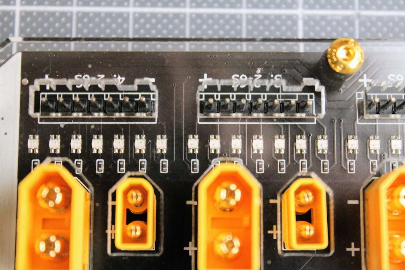
Charger board balance ports also have resettable thermal fuses for each individual cell. LED lights up when the thermal fuse takes the protection from overcurrent or short.
Compared to my old 2S-3S charging board this HGLRC Thor Pro charging board is a huge improvement in safety and featurewise.
Charging
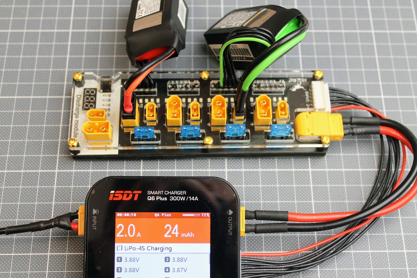
Caution! You should only use the batteries with the same cell count and the battery voltages should not differ more than 0.1V per cell. Never leave the batteries unattended while they are charging or discharging!
HGLRC Thor charger board has 4 XT30 and XT60 ports for up to 4 batteries connected in parallel. When charging the batteries in parallel you should have in mind that total charging current is divided between the count of the batteries, meaning if you provide 10A of charging current to the board with 4 batteries, it will provide the 10A/4=2.5A for each of the battery. So if you want to charge multiple batteries in parallel, you should multiply the charging current by the number of the batteries. I usually charge from 1C to 2C current rating for each battery.
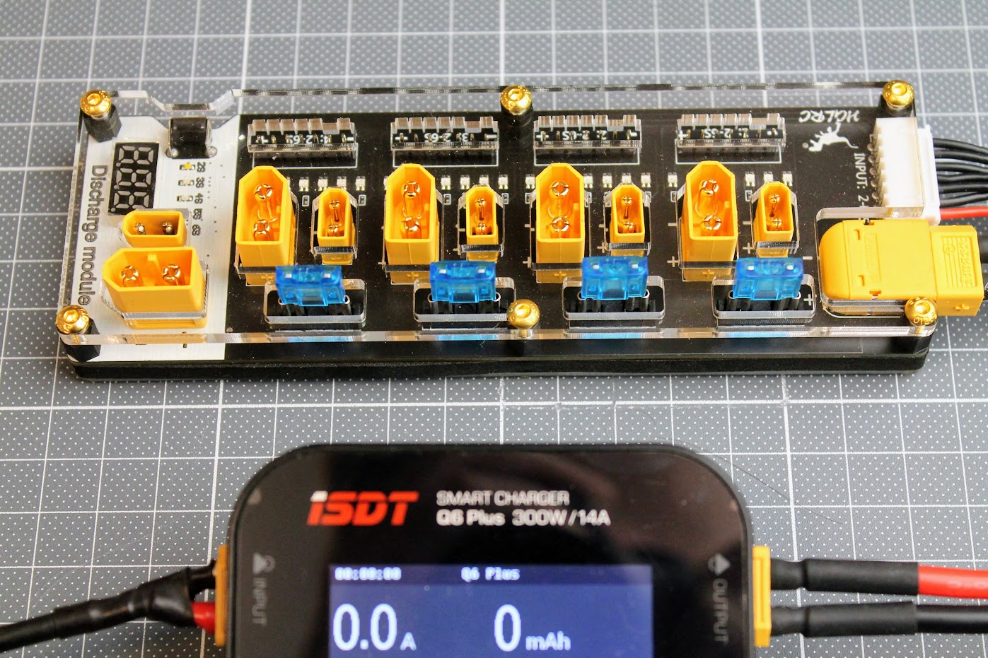
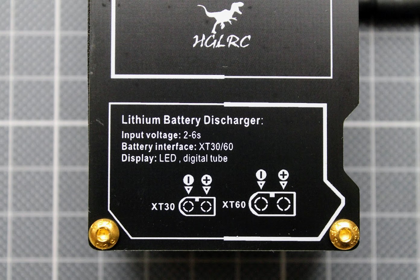
Discharging
This is very handy feature. There are often some lipo batteries left charged after the flying session. Lipo batteries don’t like to be left fully charged for a long period of time. They may puff, damage or degrade if left charged even for a few days. So it is recommended to discharge the li-po batteries to the storage voltage (3.7-3.8V) to keep them healthy.
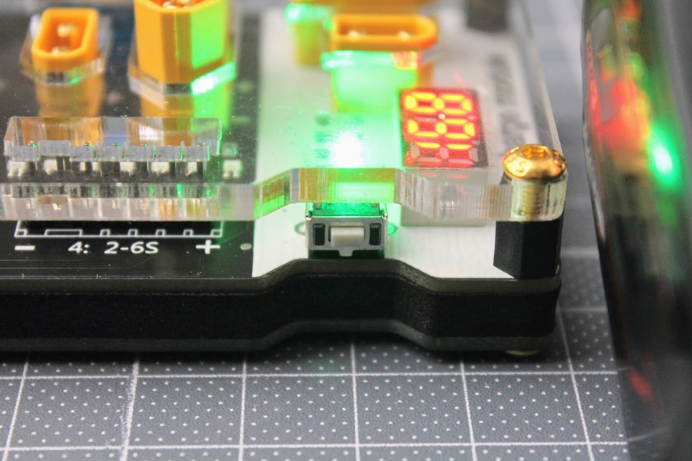
The bottom part of the charger board is actually the discharger. It has XT30 and XT60 ports, battery voltage display, cell count LED indicators and the push button for the cell count selection.
Right after the battery is plugged in the 7 segment display will show the total battery voltage. And the discharge process will start automatically.
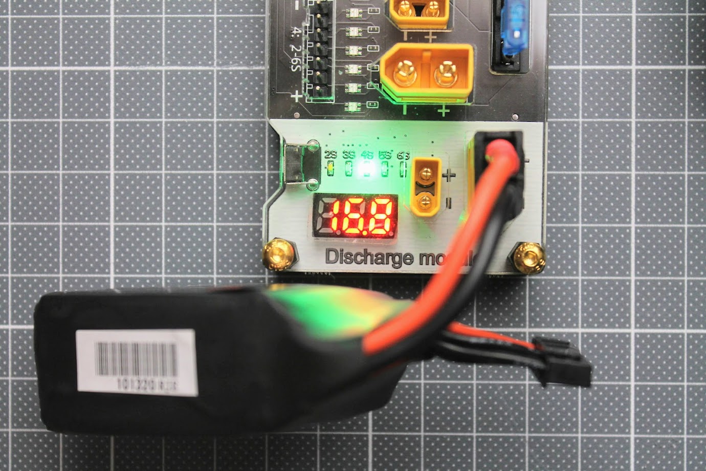
Each time the battery is plugged in you need to select the cell count of the battery by pressing the pushbutton on the side of the board. Otherwise it will discharge to the default 2S setting.
I wish it could detect the cell count or could remember the last setting rather than always use the 2S discharge setting.
I have tried to measure the discharge current with my power meter, but the current was too low for this meter to register.
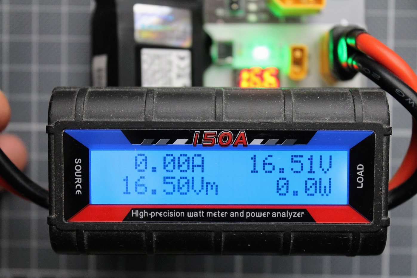
So I’ve used the multimeter to measure the discharge current and it was about 45mA (0.045A) on 4S battery. It took about 7 hours to discharge the 4S 500mAh battery to the storage voltage. The discharge current is too small and the discharge process takes too much time.
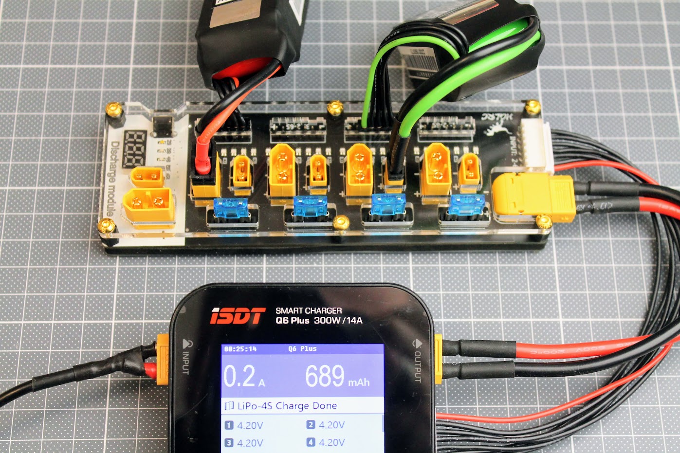
The final voltage of the battery was 15.2V (or 3.8V per cell) after the process finished so the board discharged the battery to the correct voltage.
Final thoughts
HGLRC Thor Pro battery charger board is really well manufactured parallel charging board. It can safely charge up to 4 batteries simultaneously, connected in parallel. XT30 and XT60 ports fits all the 2S-6S batteries I have (except obviously the 1S ones). Multiple fuses makes this charger much safer to use. I feel much more confident in parallel charging with this HGLRC Thor Pro charger board.
The discharge feature is pretty much useless as it only discharges at very slow rate (only 0.045A) and it takes hours to discharge the battery to the storage voltage. The discharger still might be useful as battery voltage checker device. You may plug the discharged battery briefly in the discharger port and check the voltage.
You can always use the parallel charger board to parallel discharge your batteries. If your charger is capable of high discharge current (like ToolkitRC M6D) or you use a special discharger (like ISDT Smart Discharger) you can discharge up to 4 batteries simultaneously with this HGLRC Thor Pro charger board.
Available @
HGLRC: https://www.hglrc.com/products/hglrc-thor-lipo-battery-balance-charger-board-pro
Aliexpress: https://www.aliexpress.com/item/1005002966733248.html
Disclaimer: This item was supplied by HGLRC for a fair and unbiased review. HGLRC never asked for a positive review and never influenced my opinion in any way. I’m trying my best to stay uninfluenced and give only my own opinion. All affiliate links if there are any help me purchase items for future reviews and tests.
]]>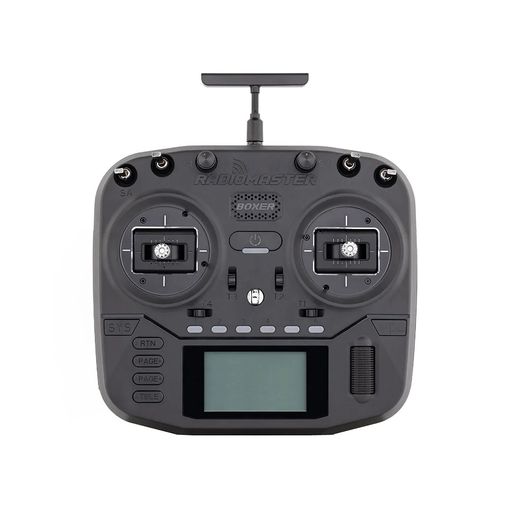
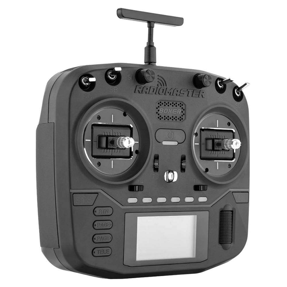
Radiomaster Boxer is wider (235mm) than Radiomaster TX16s radio (183mm), but is significantly shorter than TX16s, thus making it smaller and lighter radio. Design wise it has many similarities with TBS Mambo radio, probably could be called inspired by it.
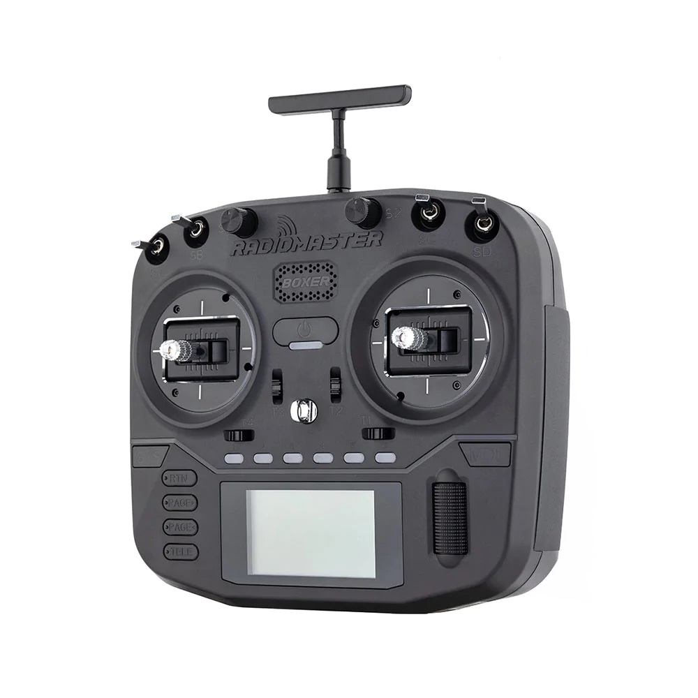
On the top side of the radio you will find the new latching push switch and momentary switch. Just like on the TBS Mamba radio.
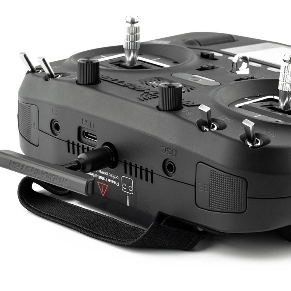
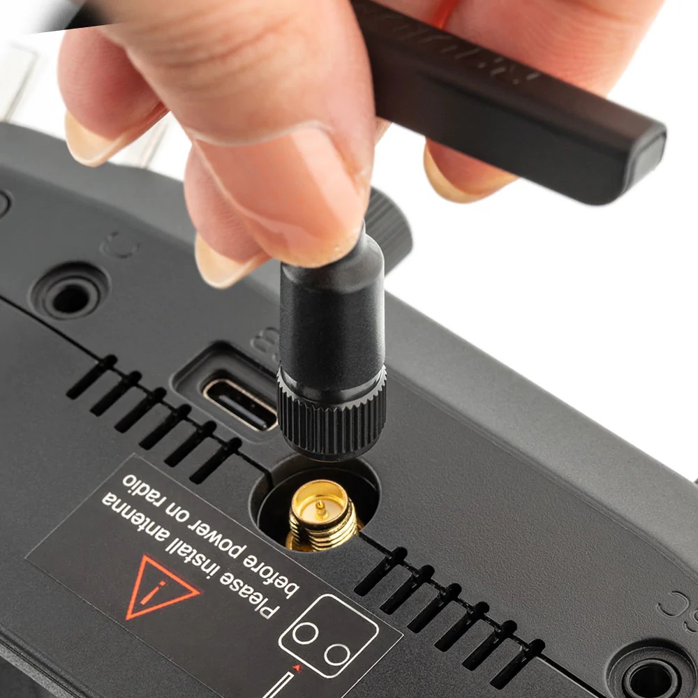
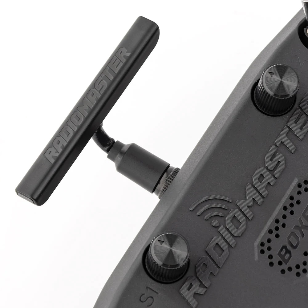
Boxer has T-shape bendable and removable antenna.
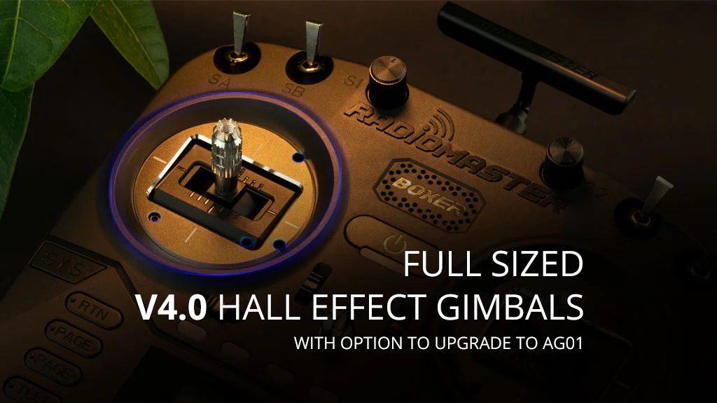
Radiomaster Boxer has full size easy adjustable gimbals. They can be upgraded with the high quality AG01 gimbals
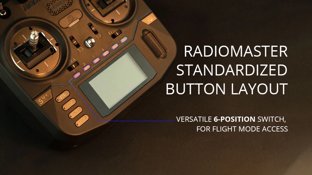
6 position switches were moved from the top to the bottom part, right over the LCD screen. By the way it was Jumper who introduced them first.
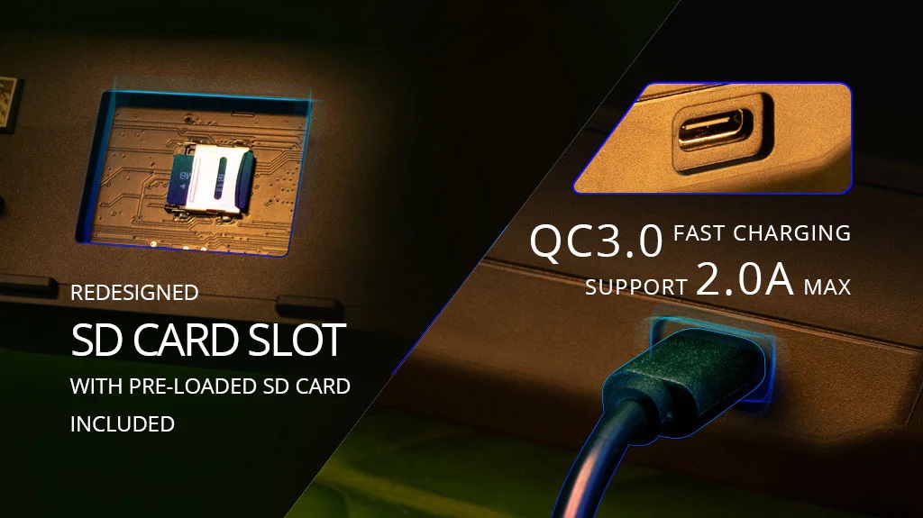
Boxer can be charged by USB-C cable with a charger supporting QC3.0 fast charging with up to 2.0A.
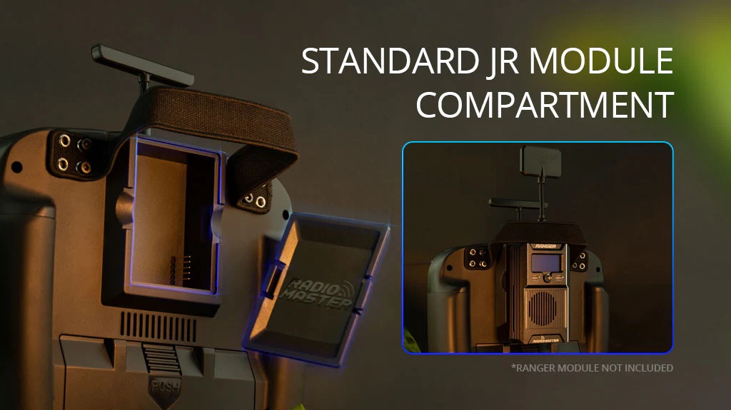
Radiomaster Boxer also has standard JR type bay for full size external modules.
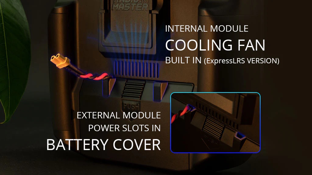
Internal ExpressLRS module provides up to 1W of RF output and is actively cooled with internal cooling fan.
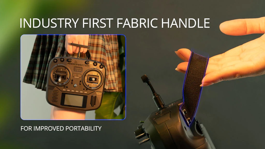
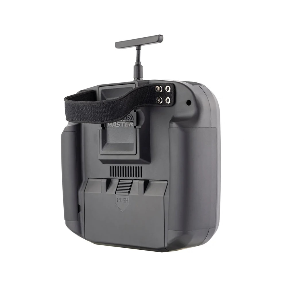
Radiomaster Boxer has never seen before soft fabric handle for weight and space savings.

Radiomaster Boxer can be purchased @
RadioMaster: https://www.radiomasterrc.com/products/boxer-radio-controller-m2
Features
- Available with built-in ExpressLRS or 4-in-1/CC2500 MPM RF modules
- Featuring a powerful STM32VGT6 processor with 1MB RAM
- Preinstalled EdgeTX firmware
- Internal ELRS module capable of 1,000Hz refresh rate
- Adjustable ELRS RF output (30dBm max FCC or 20dBm Max EU LBT)
- 4-in-1 or CC2500 only version capable of up to 20dBm RF output
- QC3.0 fast charging support 2.0A MAX
- Compact design with excellent ergonomics
- New low-profile latching SE switch and momentary SF switch
- Oversized battery compartment- Space for a 2S 6200mAh pack, up to 20-hour duration (Batteries not included)
- Full sized V4.0 Hall effect gimbals as standard, upgradable to AG01 CNC Hall effect gimbals
- Standard JR module compartment
- Internal module cooling fan built in (ELRS version)
- RadioMaster standardized button layout
- Versatile 6-position switch for flight mode access
- Adjustable and Removable T-shape Antenna
- Industry first fabric handle for improved portability
- Changeable, ergonomic grips
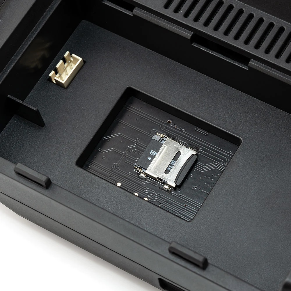
- Redesigned SD card slot with pre-loaded SD card included
- External module power slots in battery cover
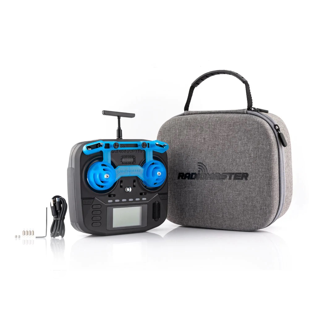
- RadioMaster signature carry case and gimbal protector are included as standard to ensure your radio stays safe while on the move
Specification
- Item: BOXER Radio
- Size: 235*178*77mm
- Weight: 532.5g
- Frequency: 2.400GHz-2.480GHz
- Internal RF Options: CC2500 multi-protocol / 4-in-1 multi-protocol / ELRS 2.4GHz
- Supported protocols: Module dependent
- Transmitting Power CC2500 and 4IN1: Max 20dBm
- Transmitting Power ExpressLRS: Max 30dBm (international) / Max 20dBm (EU LBT)
- Cooling fan: Built in (ELRS version)
- Voltage Range: 6.6-8.4V DC
- Radio Firmware: EdgeTX (Transmitter) / Multi-Module (RF module) / ELRS
- Channels: Max 16 channels (Receiver dependent)
- Battery: 7.4V 2-cell Lithium-Polymer / Two 3.7V 18650 Lithium-Ion cells (batteries not included)
- Display: 128*64 Monochrome LCD display
- Gimbal: High precision 4.0 Hall gimbals as standard (AG01 Optional)
- External module: JR/FrSKY/Crossfire compatible
- Upgrade Method: USB/SD card & EdgeTX Companion PC software
Radiomaster Boxer Radio User Manual: https://cdn.shopify.com/s/…/files/Boxer_Radio_User_Manual.pdf
]]>One of the most notorious problems with ExpressLRS hardware is that some manufacturers hardware have unacceptable high frequency error. And in the high or low temperatures it gets even worse. There is certain threshold of the frequency error for the link to work. Up to 40 ppm error (=~100 kHz) frequency difference is considered still acceptable.
Detailed explanation about the Crystal Oscillator (XO) Frequency Error can be found on the expresslrs.org webpage: https://www.expresslrs.org/3.0/hardware/crystal-frequency-error/
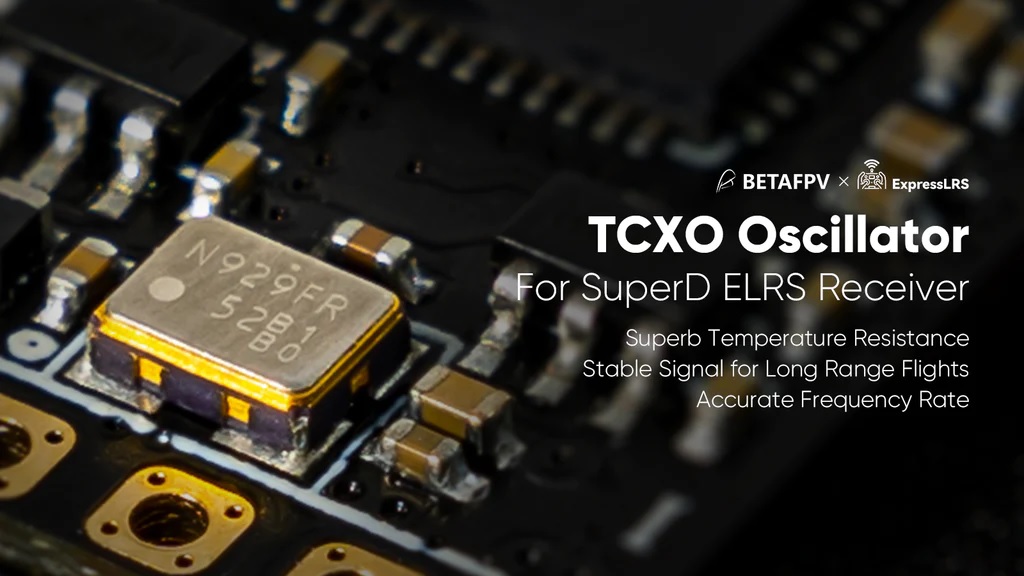
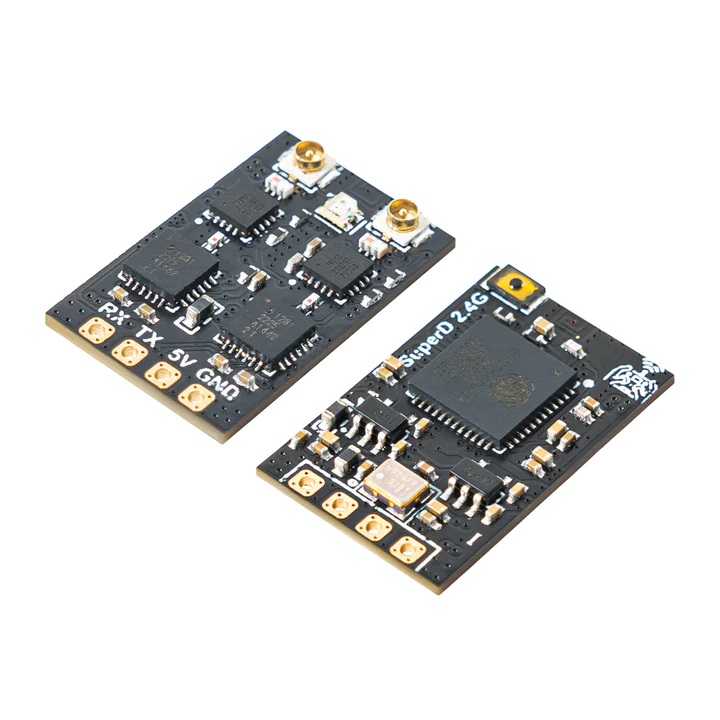
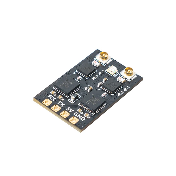
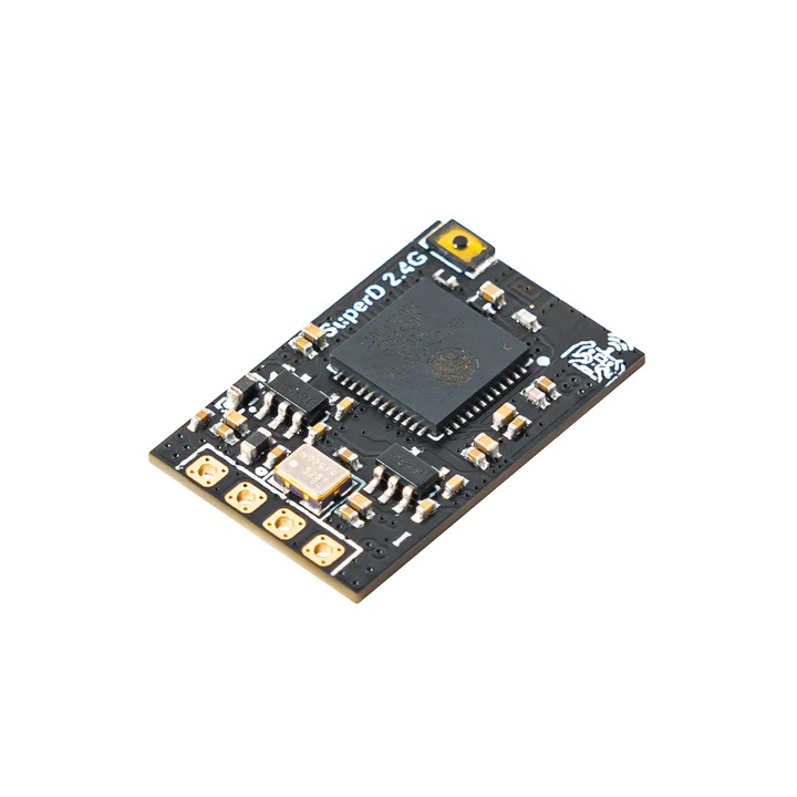
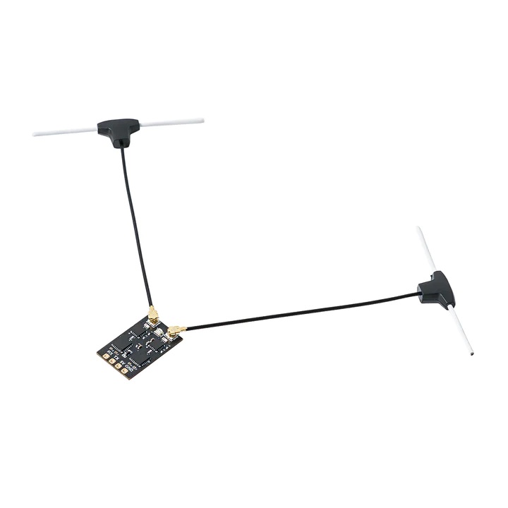
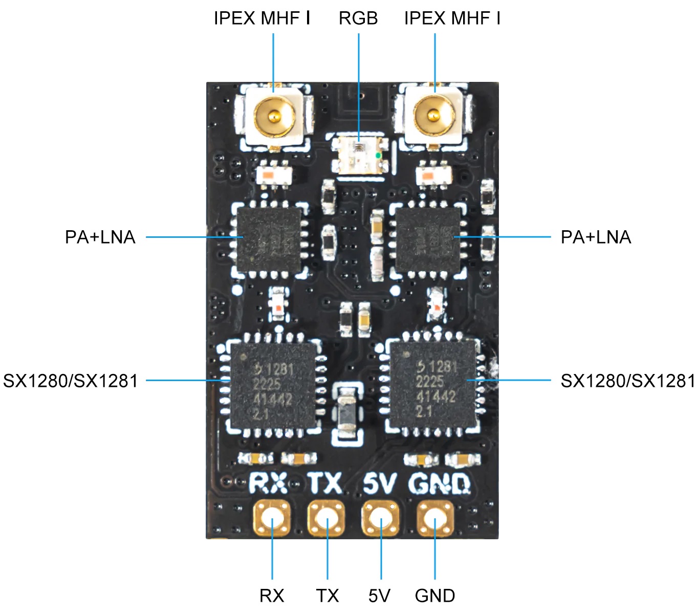
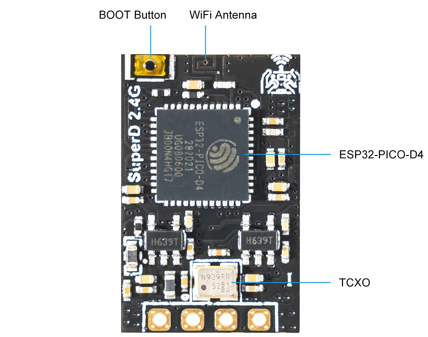
BetaFPV SuperD receiver
BetaFPV SuperD receiver is the first ExpressLRS receiver with full dual diversity and temperature compensated crystal. Receiver has two SX1280 LoRa RF ICs, two PA/LNA amplifiers and two antenna connectors. Power amplifier provides 100mW for telemetry link.
Available @ BetaFPV: https://betafpv.com/products/superd-elrs-2-4g-diversity-receiver
Aliexpress: https://www.aliexpress.com/item/1005004938838056.html
Specifications
Item: BETAFPV SuperD ELRS 2.4G Diversity Receiver
MCU: ESP32 PICO D4, dual SX1280 (SX1281)
Antenna Connector: IPEX MHF 1/U.FL
RF Frequency: 2.4GHz (2400~2480MHz)
Telemetry Power: 20dBm (100mW)
Receiver Protocol: CRSF
Input Voltage: +5V DC @ “+” pad
PCB Size: 22mm*14mm
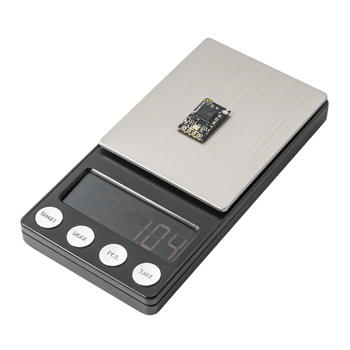
Weight: 1.1g excluding antenna
Crystal oscillator: high-quality TCXO
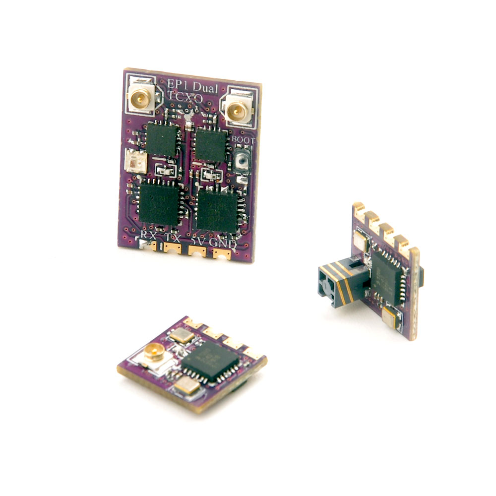
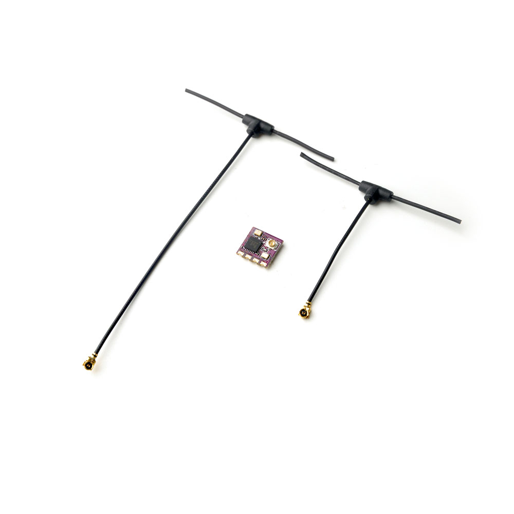
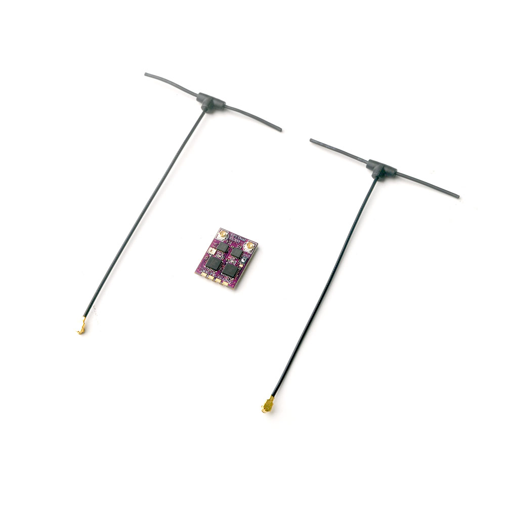
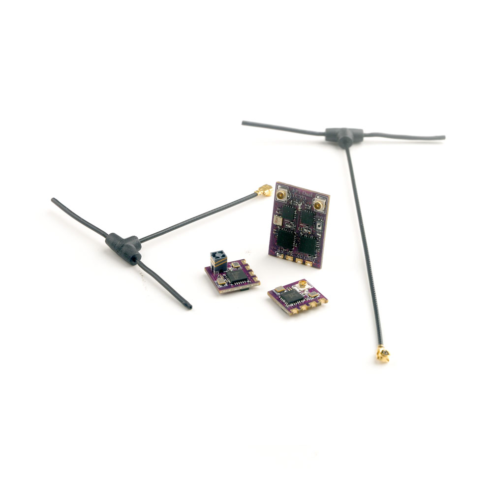
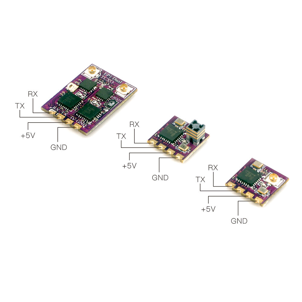
Happymodel TCXO EP1,EP2 and EP1 Dual receivers
Happymodel has also released their three EP1, EP2 and EP1 Dual ExpressLRS receivers with temperature compensated crystals (TCXO).
Available @
Banggood: https://www.banggood.com/HappyModel-EP1-Dual-or-EP1-RCXO-or-EP2-TCXO-…-1975740.html
Makerfire: https://shop.makerfire.com/…/happymodel-ep1-tcxo-and-ep2-tcxo-2-4ghz-expresslrs-receiver-elrs
Aliexpress: https://www.aliexpress.com/item/1005002459298315.html
EP1 TCXO Receiver
Type: ISM2.4GHz
ESP8285 MCU
SX1280(SX1281)IMLTRT RF Module
Omni directional antenna
Frequency Range: 2400 MHz to 2500 MHz
Receive refresh rate: 25HZ~500Hz
Working voltage: 5V
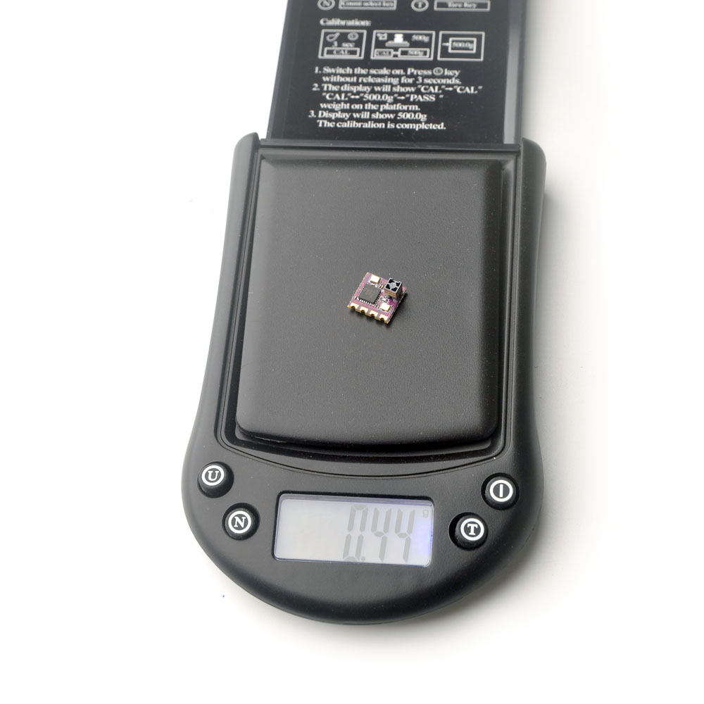
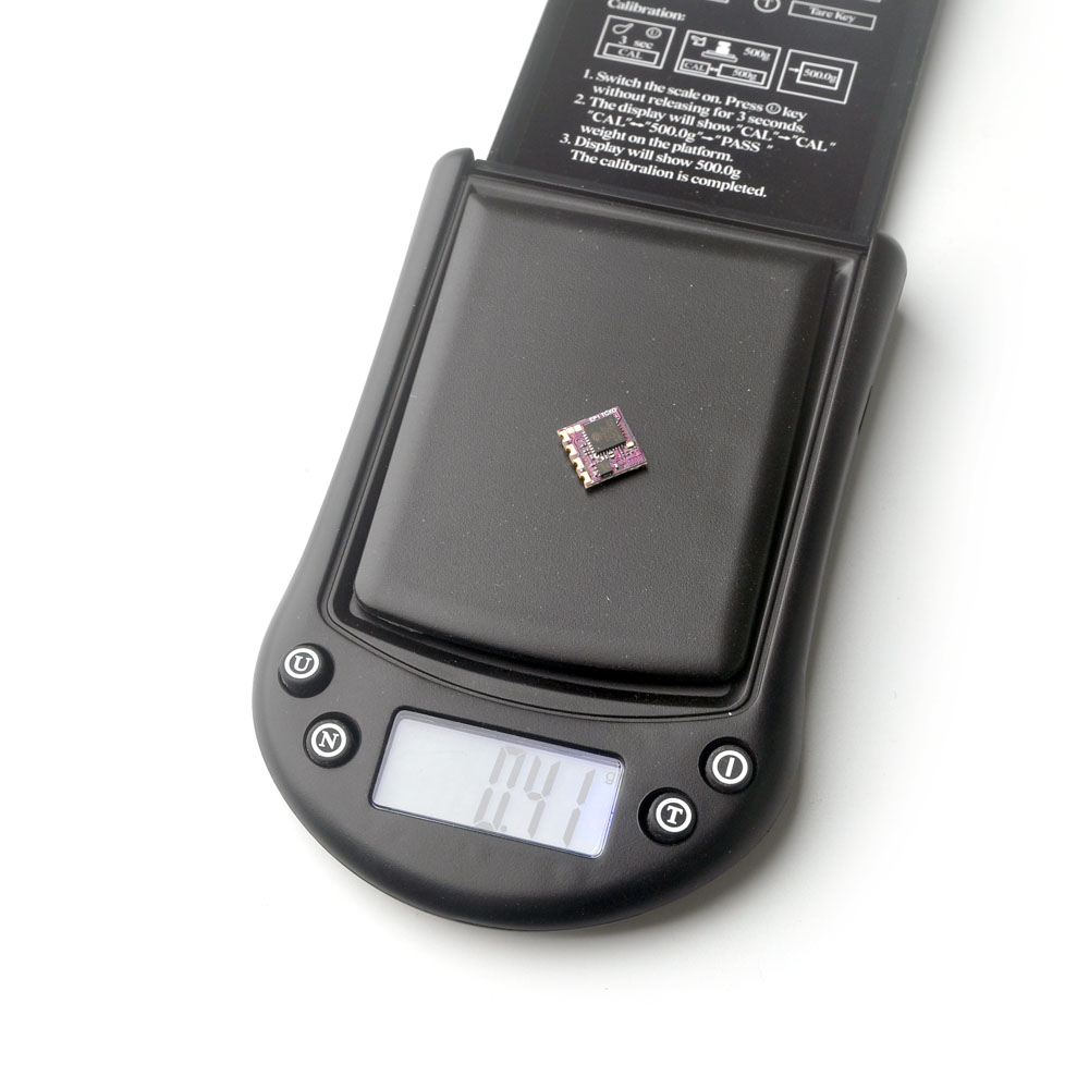
Weight: 0.41g (without antenna)
Dimension: 10mm*10mm*6mm
Peak gain: 2.23dB
Default Firmware out of factory: HappyModel_EP_2400_RX V2.2 version
Built-in a TCXO (temperature compensated crystal oscillator)
EP2 TCXO Receiver
Type: ISM2.4GHz
ESP8285 MCU
SX1280(SX1281)IMLTRT RF Module
SMD Ceramic antenna
Frequency Range: 2400 MHz to 2500 MHz
Receive refresh rate: 25HZ~500Hz
Working voltage: 5v
Weight: 0.44g
Dimension: 10mm*10mm*6mm
Peak gain: 3.7dB
Default Firmware out of factory: HappyModel_EP_2400_RX V2.2 version
Built-in a TCXO (temperature compensated crystal oscillator)
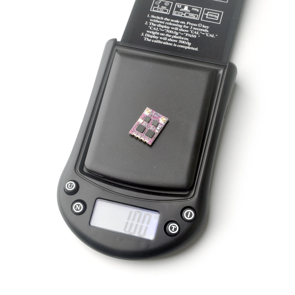
EP1 Dual TCXO Receiver
Type: ISM2.4GHz
ESP32 PICO D4, dual SX1280(SX1281)
Antenna connector: IPEX MHF 1/U.FL
RF Frequency: 2.4GHz (2400~2480MHz)
Telemetry power: >19dbm
Receiver protocol: CRSF
Input voltage: +5V DC @ “+” pad
PCB size: 19mm x 14mm
Weight: 1g (excluding antenna)
Built-in a TCXO (temperature compensated crystal oscillator)
Firmware: HappyModel EP1 Dual 2400 RX (starting from ExpressLRS V3.0)
Both manufacturers dual diversity receivers have multicolored LED for status indication. SuperD and EP1 Dual receiver RGB status indication is shown below.
| RGB Color | Status | Description |
| Rainbow | Fade effect | Power on |
| Green | Quick flash | WIFI upgrading mode |
| Red | Quick flash | No RF chip detected |
| Orange | Double flash | Binding mode |
| Orange | Triple flash | Connected, but mismatched model-match configuration |
| Orange | Slow flash | Waiting for connection |
| Solid on | Connected and color indicates packet rate (see below) |
The RGB light color corresponding to the packet rate

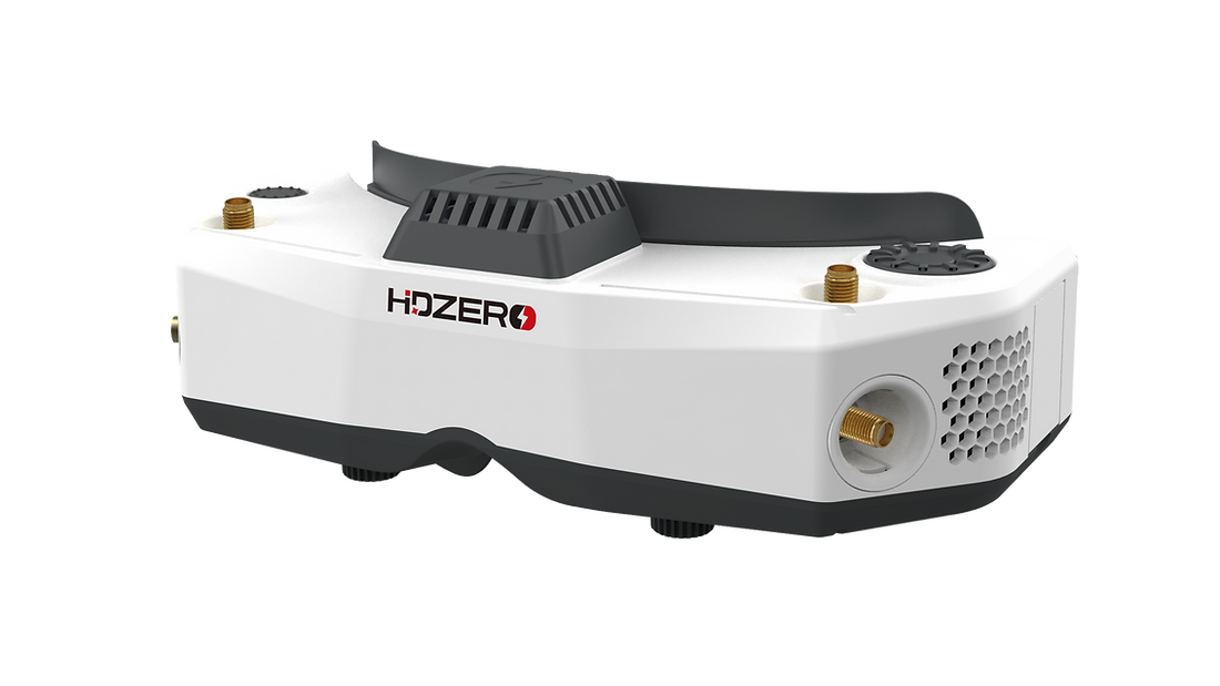
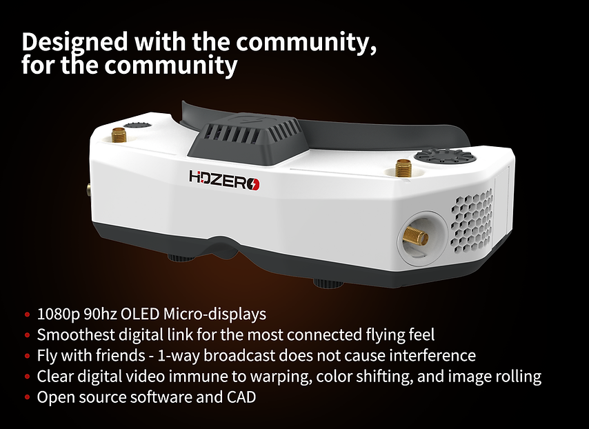
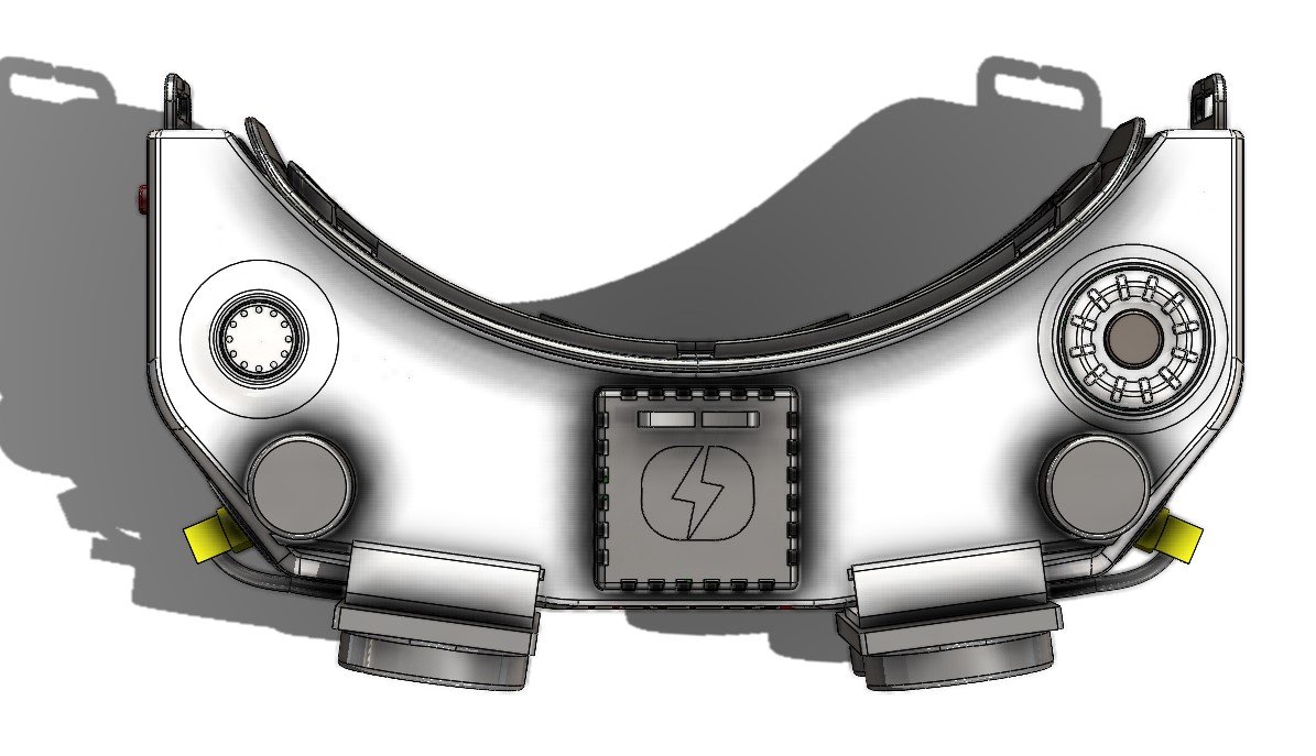
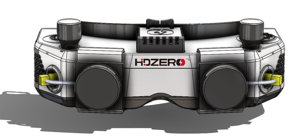
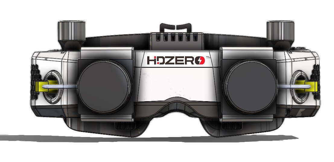
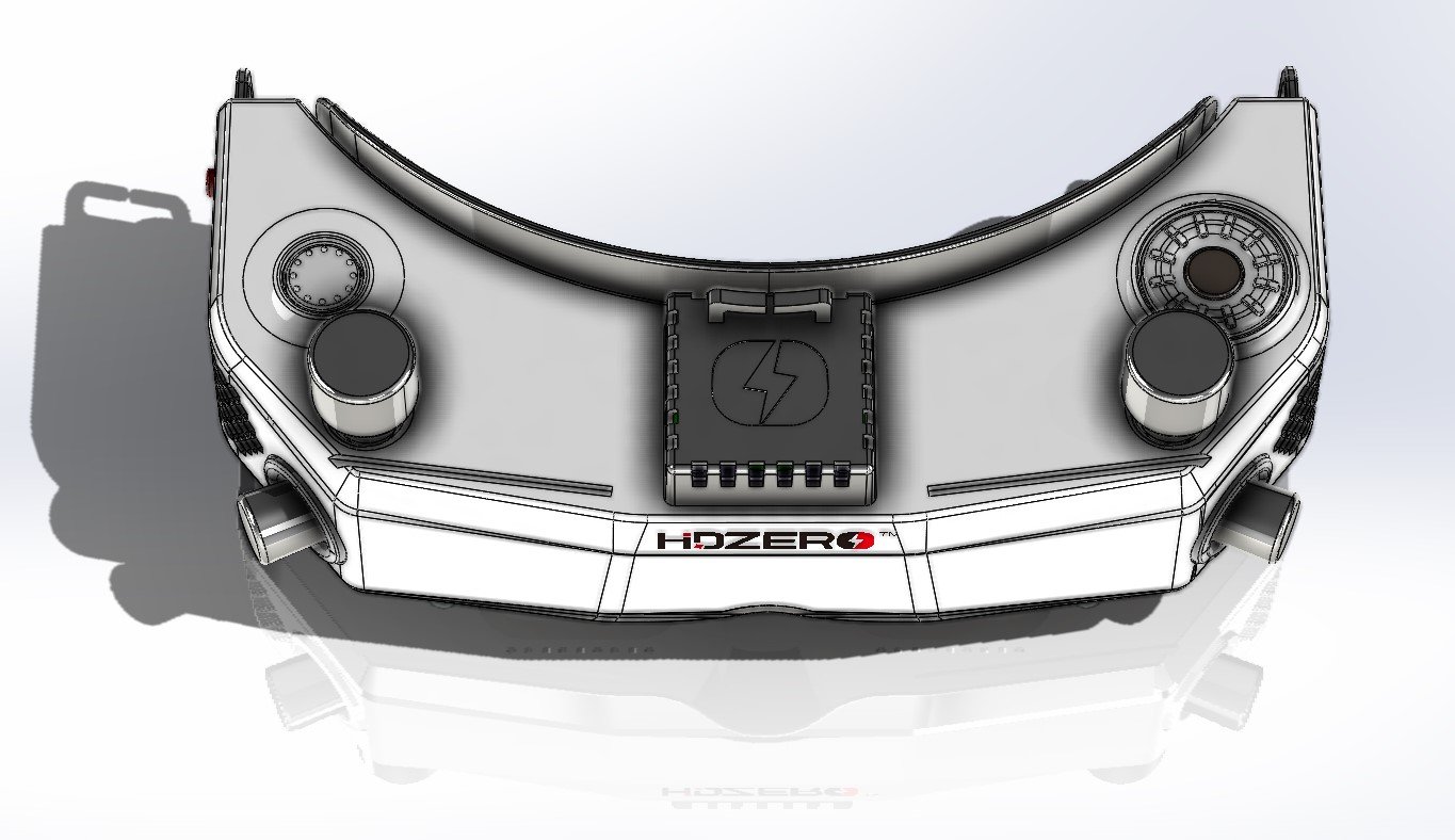
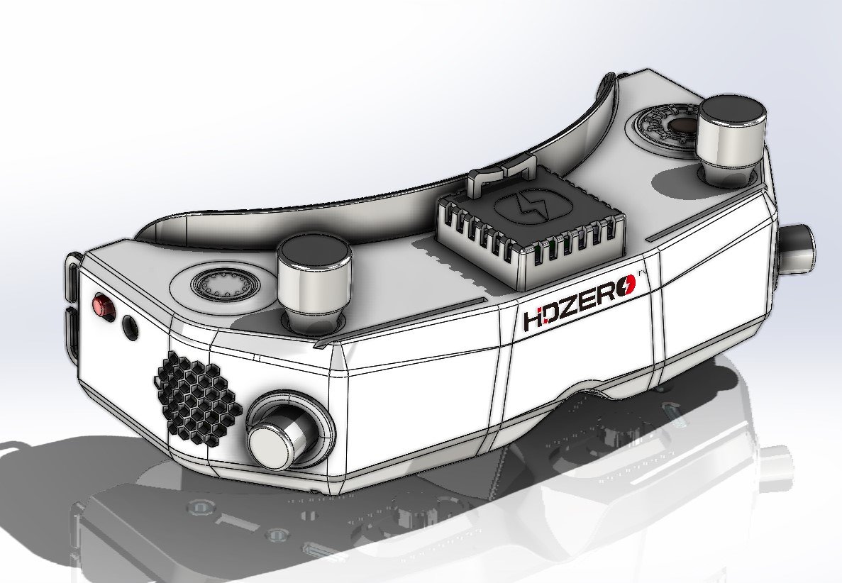
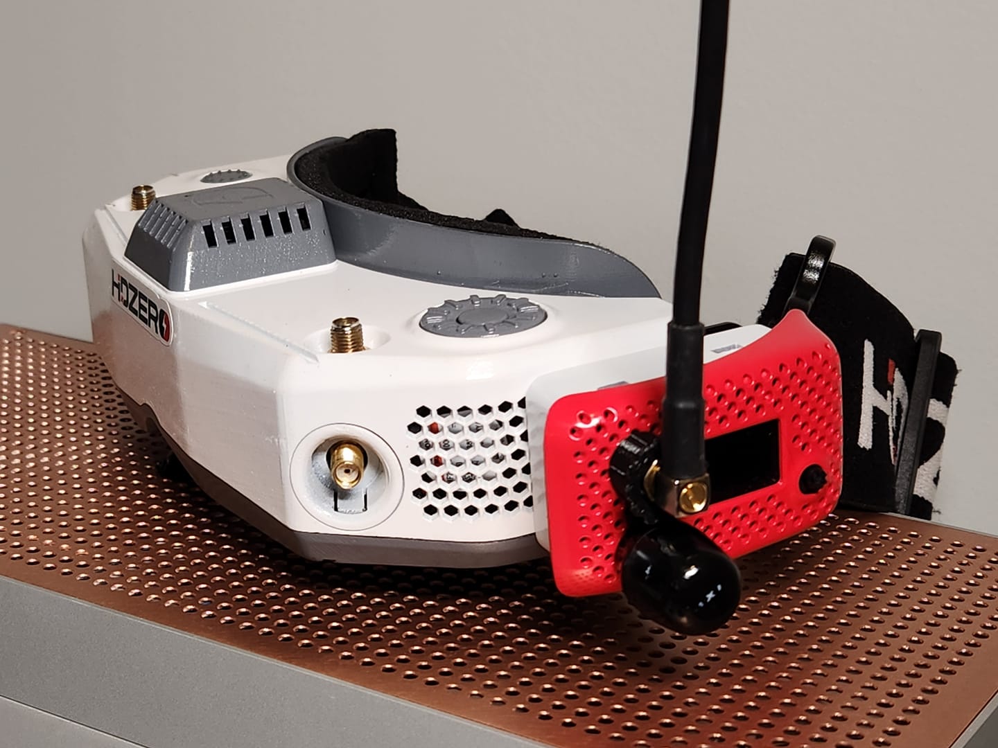
HDZero goggles have 1920×1080 native resolution and 90Hz refresh rate OLED displays. This is the best resolution goggles on the market with the 90Hz refresh rate.
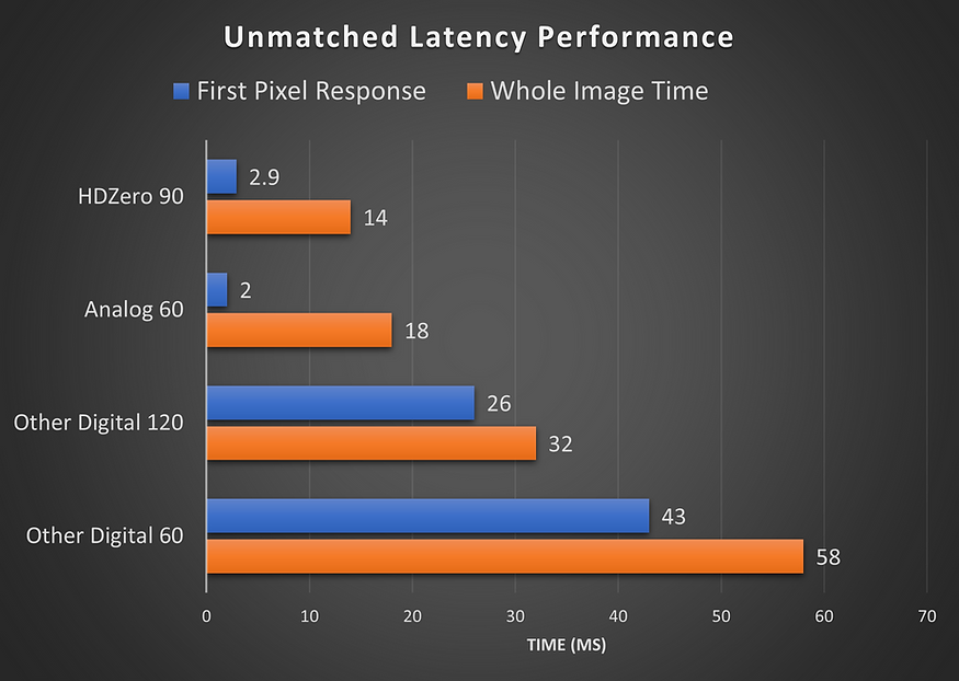
HDZero is digital wireless video transceiver technology developed and fully owned by Divimath Inc. A HDZero transmitter broadcasts uncompressed video streams, and HDZero receivers are able to pick up the video with less than 1ms fixed latency. With its smart de-Noise techniques (patent pending), HDZero is able to reach a much longer range per mW.
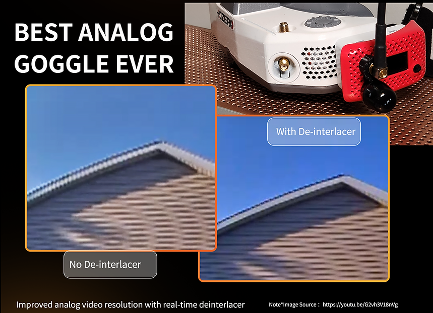
HDZero goggles have optional analog FPV video module bay with real time analog video deinterlacer. So the analog video quality should be superior comparing to other analog goggles.
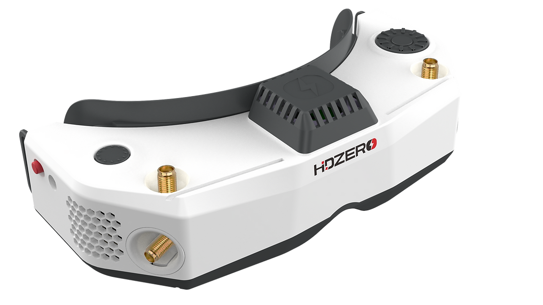
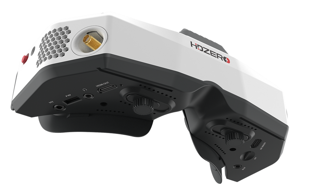
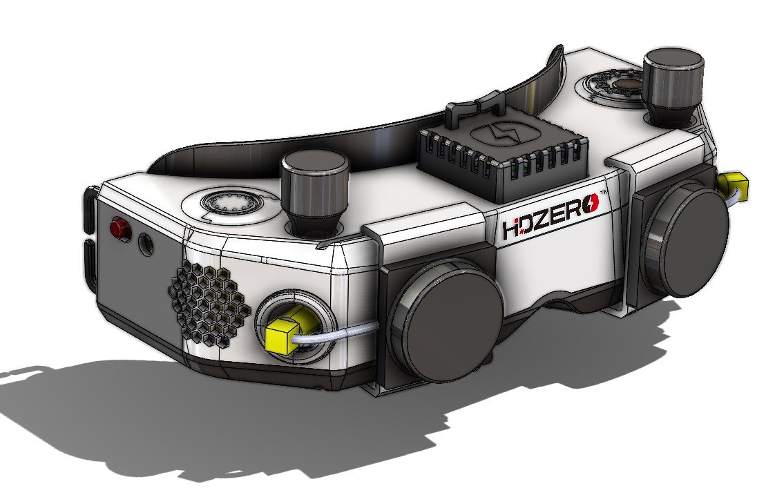
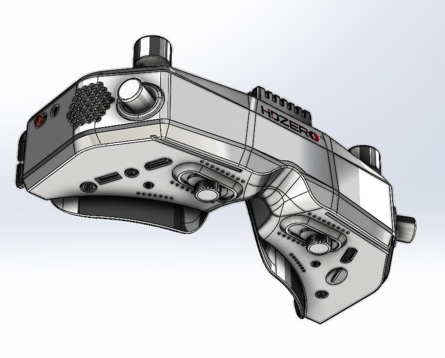
HDZero goggles have built in digital FPV receiver, but also features all kinds of possible inputs and outputs – HDMI in and HDMI out ports, 3.5mm AV in port and 3.5mm audio out for headphones and input for external microphone. Goggles even have built in microphone for narrated DVR recordings of the FPV feed.
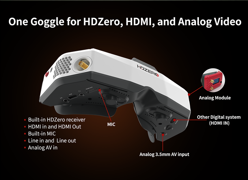
There are special mounting rails for the patch antennas on the HDZero goggles.
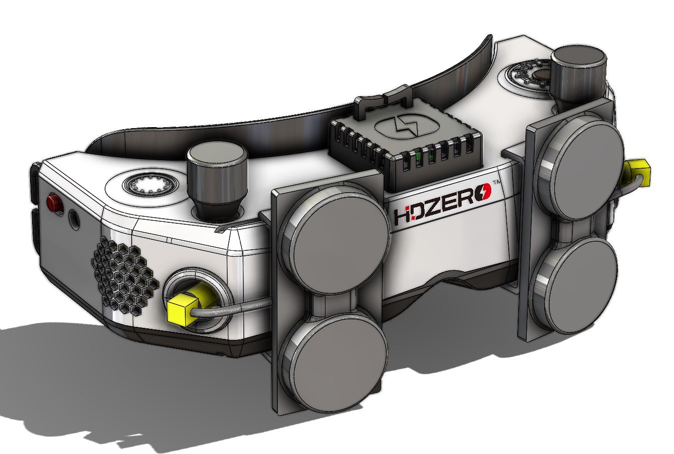
HDZero goggles software is Open Source and is open for the community (however it is still not available on the gitHub https://github.com/hd-zero/hdzero-goggle at the moment of writing this post). Also the CAD files for printing and customizing the goggle shell is available.

Specifications:
- HDZero Camera glass-to-goggle glass latency: <3ms
- Adjust IPD range: 57-70mm
- Adjustable focus range: +6?to -6 diopter
- Full HD 1920x1080p 90fps OLED micro display
- FOV: 46deg (16:9 aspect ratio) and ~ 38deg (4:3 aspect ratio)
- Input voltage:
7V-21V (2S-5S)7V–25.2V (2S-6S)1
1 DO NOT use a 6S or above HV lipo to power on the goggle, it will permanently damage
the goggle.
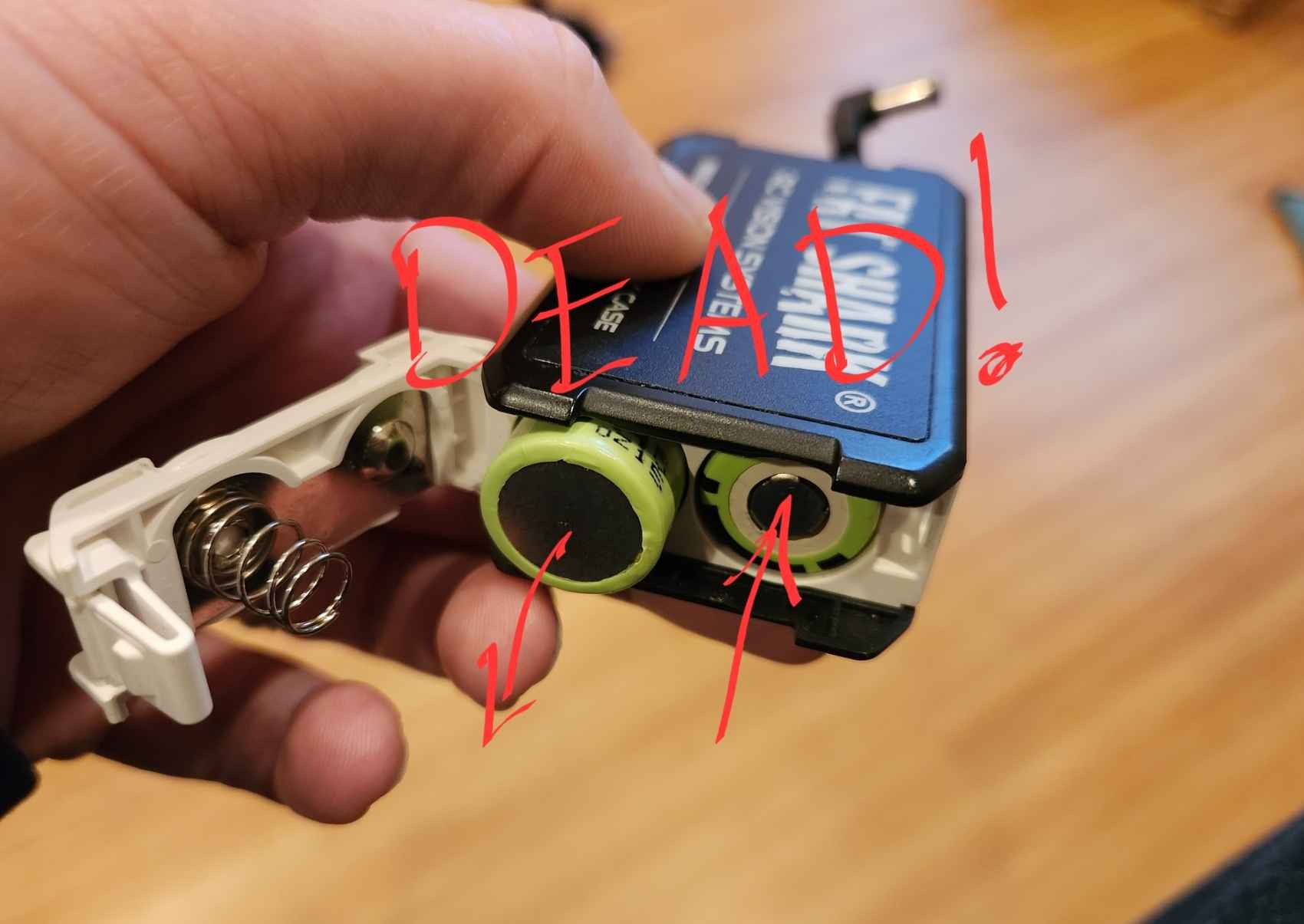
2 18650 battery cases can kill your goggle (blow the fuse). Always install batteries in
correct polarity, check with case’s battery checker beforehand, if the checker lights
don’t turn on, the batteries are installed backwards and the goggle’s fuse will blow to
protect the goggle. This can be repaired by replacing the fuse inside the goggles, but at
owner’s own cost.
Includes:
- 1x HDZero goggle
- 1x wide face plate
- 1x narrow face plate
- 1x foam padding
- 1x Goggle Strap
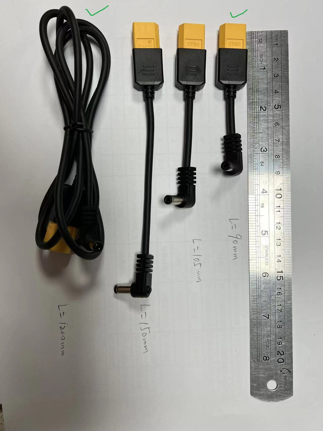
- 1x 1200mm XT60 cable
- 1x 150mm HDZero VTX programing cable
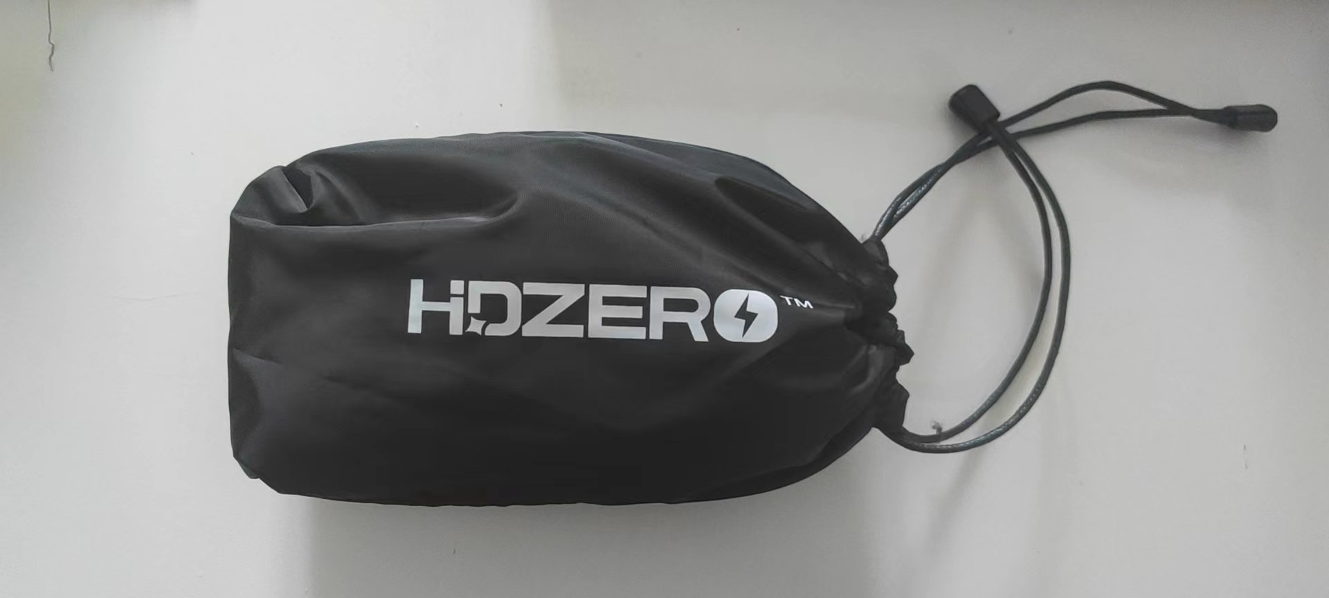
- 1x Thick Canvas Goggle Bag
- 1x Lens cloth
A note about the power supply
HDZero Goggles support 6s input (same power regulator as Freestyle VTX batch 2). For good measure, only plug in 6s battery when power switch is in off position. So far, the only blown fuse case has been from?reverse polarity, not 6s voltage.
Estimated shipping?date of the first batch is Dec 15?2022. Second batch – January 2023. Third batch March 2023.
HDZero Goggles User Manual: https://www.hd-zero.com/_files/ugd/967e02_2cd839d8532f4a6f812c4eaab1053da5.pdf
HDZero Goggles
Available (pre-order): https://www.hd-zero.com/product-page/hdzero-goggle
HDZero Analog video module bay
The analog module bay will not include WiFi for the first version and its price is reduced to $29.99. Later when WiFi is working you may purchase a new board to install that adds WiFi for $29.99.
Available (pre-order): https://www.hd-zero.com/product-page/hdzero-goggle-expansion-module-v1-without-wifi
HDZero Nano 90 camera
The new Nano 90 camera is available to order in limited quantities. This camera offers 720x540p 90 FPS video and, in the future, will add a 720x540p 60 FPS mode which will increase RF signal quality and penetration.
Available: https://www.hd-zero.com/product-page/runcam-hdzero-nano-90
Information from Carl Zhou on May 16, 2022
Our goggle has progressed greatly since I last discussed it with you all. Thank you for your input early on, it was invaluable – this will be your goggle!
I want to set expectations about release date first. The goggle will be ready for a small group of testers in the June/July timeframe. General availability will be around September/October timeframe. If you have a set of goggles with HDMI input, I recommend purchasing the HDZero VRX now – don’t hold off flying HDZero all summer!
Whether you fly HDZero or analog, I’m confident that these will be your favorite set of goggles to reach for.
– On/off sliding switch – be confident that the goggle is on or off at a glance or by feel
– Designed for open source, the new goggle runs Linux. All code for the user interface is new and will be open source
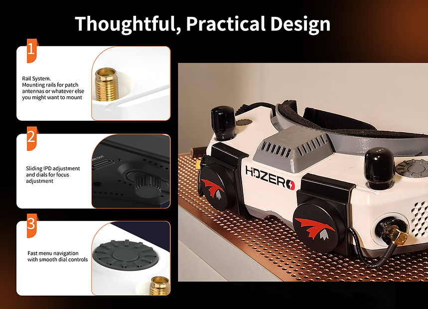
– 90Hz 1080p OLED screens with sliding IPD adjustment and dials for focus adjustment
– By integrating the entire goggle display pipeline with HDZero’s fixed-latency video transmission, these goggles achieve 4ms glass-to-glass sub-frame latency with no jitter or dropped frames
– Mounting rails for patch antennas or whatever else you might want to mount
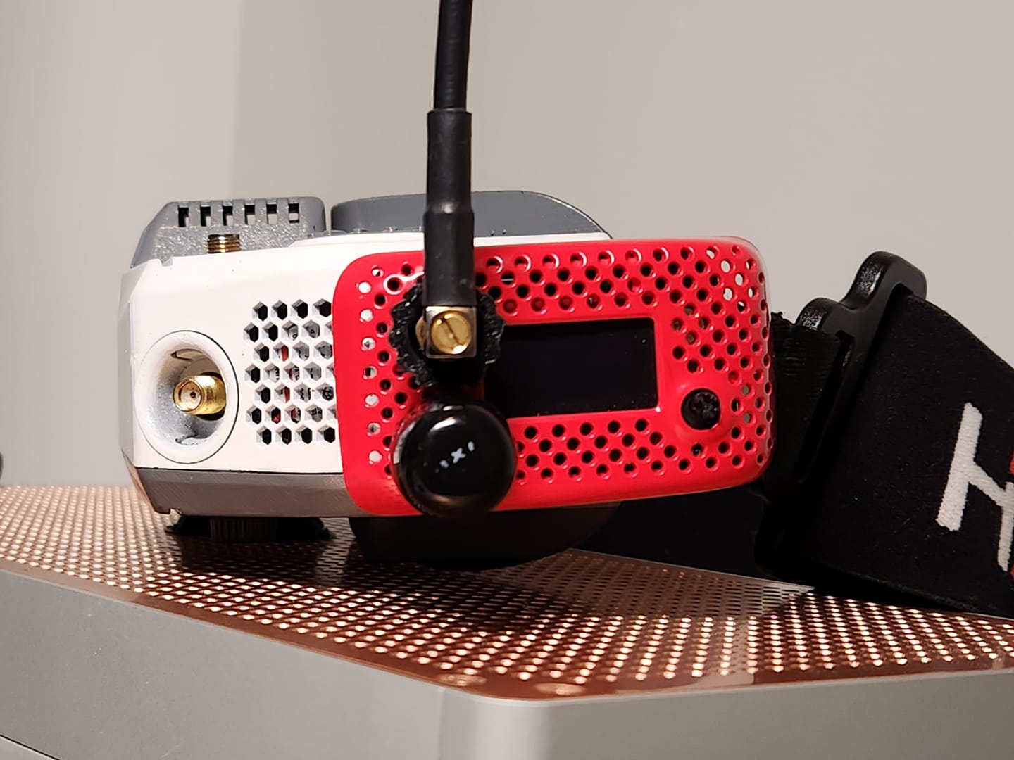
– Recessed front SMA jacks so you don’t have to remove antennas when packing the goggle away. Whether you install stubby antennas or TrueRC slide on patches, setup and teardown will be fast and easy
– Three independently addressable fans work in combination to cool the internals and prevent fogging. They are soft mounted to prevent screen vibration and noise
– HDMI input so you can use a ground station receiver, use for simulators, on the go movies, etc…
– HDMI output so you can share your video feed to others
– 3.5mm combination headphone / microphone jack so you can listen to analog or HDMI source audio or use a high-quality microphone for the pit-mic feature
– 3.5mm analog video/audio input for use with ground station inputs
– Analog input solves the vertical jitter problem found in analog OLED goggles today by using a 2D deinterlacer that adds no delay. This might be the best looking analog goggle display, despite it being a digital goggle
– ELRS backpack support so the goggle can automatically follow the channel of the VTX
– Add-on side-mounted analog module bay that accepts most of today’s analog modules
– Add-on 2.4Ghz WiFi video streaming module to live steam your flights
– Swappable faceplates to support different shaped faces and prevent light leak
Thank you,
Carl
Update on August 15, 2022
We are nearing the final stages of development. Many final touches have been determined. I have chosen some accessory parts based on user recommendations, and I think you’ll like them:
- Beta goggle ready to try at August 27th HDZero Team Race event (https://www.multigp.com/races/view/?race=24041/HDZero-Team-Race)
- Adding 1080p30 and 540p90 camera options;
- PCB assembly is complete and under testing and development
- End to end video is working (Camera -> VTX -> Goggle internal VRX -> Goggle OLED display (and HDMI output)
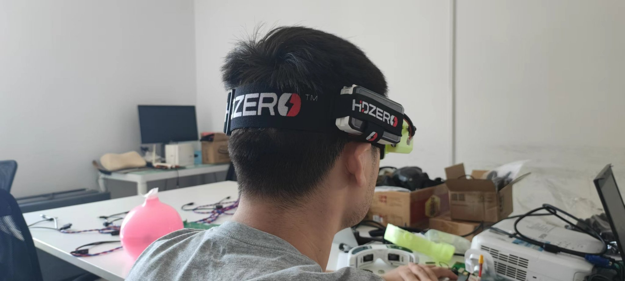
- Head strap chosen (see picture)
- Power cables chosen (see picture)
- Goggle carrying bag chosen (see picture)
- Faceplate foam chosen (see picture)
- Curved and flat faceplates are included (see picture)
Information about the Open Source on July 12, 2022
I’m happy to announce the official HDZero Open Source Project on GitHub https://github.com/hd-zero
VTX source code is the first code to be released as open source, goggle source code will be released later. We are committed to working with the community to build the best digital video system for everyone. Mechanical CAD data is also included – these products are meant to be reference designs for manufacturers to build from and to allow pilots to customize the product to their needs.
Open source VTX software allows for:
1. Community feature requests, bug reporting, and bug fix pull requests;
2. Manufacturers to make customizations for new VTXs and cameras;
3. Custom control of startup behavior;
4. Processing new commands from MSP like MSP VTX control (a replacement for Smart Audio);
5. Color OSD elements; and
6. Canvas mode (the current OSD is MSP Display Port)
Today, the VTX code is compiled with Keil C (a closed-source IDE), so we need to target a new open source compiler like SDCC.
Thanks for supporting HDZero. I’m excited for what we can build together as more of the project is open sourced.
Information about price drop on January 04, 2023
Hi all,
I am pleased to announce that the HDZero goggle is ready for full mass production with the completion of the beta testing program (100 units) and production pilot run (550 units). Many thanks to beta testers for they have volunteered their time to find bugs and propose new features. Nearly all goggles have shipped to customers: the remaining orders should be delivered in 1-1.5 weeks.
The HDZero Goggle is an amazing collaboration between the community and HDZero team. I am thankful for all the help and encouragement from the community. HDZero Goggle would not exist without this community support! I am proud that this is the best product I have made in my 25-year career. Please check if current HDZero Goggle owners are satisfied, and stop reading this post if they don’t love it! I am so humbled by the positive response I see from customers so far.
Some background about myself and my company: I immigrated to the United States in 2001 and have been an US citizen for 12 years. Divimath is an American company based in California with a factory in Shenzhen, and R&D office in Xi’an, China. We started the near zero latency video transceiver project in 2016. To my knowledge, HDZero is the only American-owned digital FPV system.
My plan is to collect a large amount pre-orders which will help lower the manufacturing cost. Please support us if you like the goggle and/or HDZero video link.
In order to help pilots afford this goggle and for HDZero to grow quickly at the start of the year, I’ve decided to lower the price of the goggle to $495 (sold directly from HD-Zero shop). This is a special promotional price, and is only available for 1 month. Current goggle customers will receive store credit for the price difference.
- Promotion period: Jan 4, 2023 to Feb 4, 2023
- Customers who bought HDZero Goggle at $599.99 will receive a $105 store credit,
- Beta testers who bought HDZero Goggle at 25% discount will receive a $79 store credit
- Orders from USA customers will be shipped no later than the second day from California
- Orders from international regions will be shipped no later than the second day from China. We can help on custom declaration.
- First 300 USA orders are ready to ship from California starting January 23rd
- First 100 international orders are ready to ship from China starting January 16th
- Orders after this will ship from the factory in order received. Note that this batch will be delivered later, starting mid-March
There are also some bundles with the goggle to save even more:
- The HDZero goggle = $495
- Expansion Module V1 (Analog only) = $29.99
- HDZero Nano 90 Camera (With 80 MIPI cable) = $64.99
- Race bundle: Nano90 Camera + 80mm MIPI cable + Race V2 VTX + Goggle = $599.99 (Save $30)
- Freestyle bundle: Micro V2 Camera+120mm MIPI cable + Freestyle VTX + Antenna + Goggle = $619.99 (Save $35)
The above items are available to (pre-)order at www.hd-zero.com/shop now. I would suggest you watch review videos from your favorite YouTuber that just released before making a decision.
Here is warranty and repair policy for the goggle:
Warranty: The HDZero Goggle can be exchanged for a new unit within 7 days for any manufacturing defects if returned in new condition. The optic module will be warrantied for repair for 6 months, and all other components, for 2 years.
Repair Centers: Divimath has setup repair centers in
- Germany for EU region
- USA for North American region
- China for Asian region
Thank you
Carl
]]>
?
DIY ExpressLRS TX Nano module
Remarks
DIY Nano TX module build uses modular design it means it uses pre build modules. Only a few additional components are used (one resistor and one capacitor). Almost anyone could build this TX module with little soldering experience.?
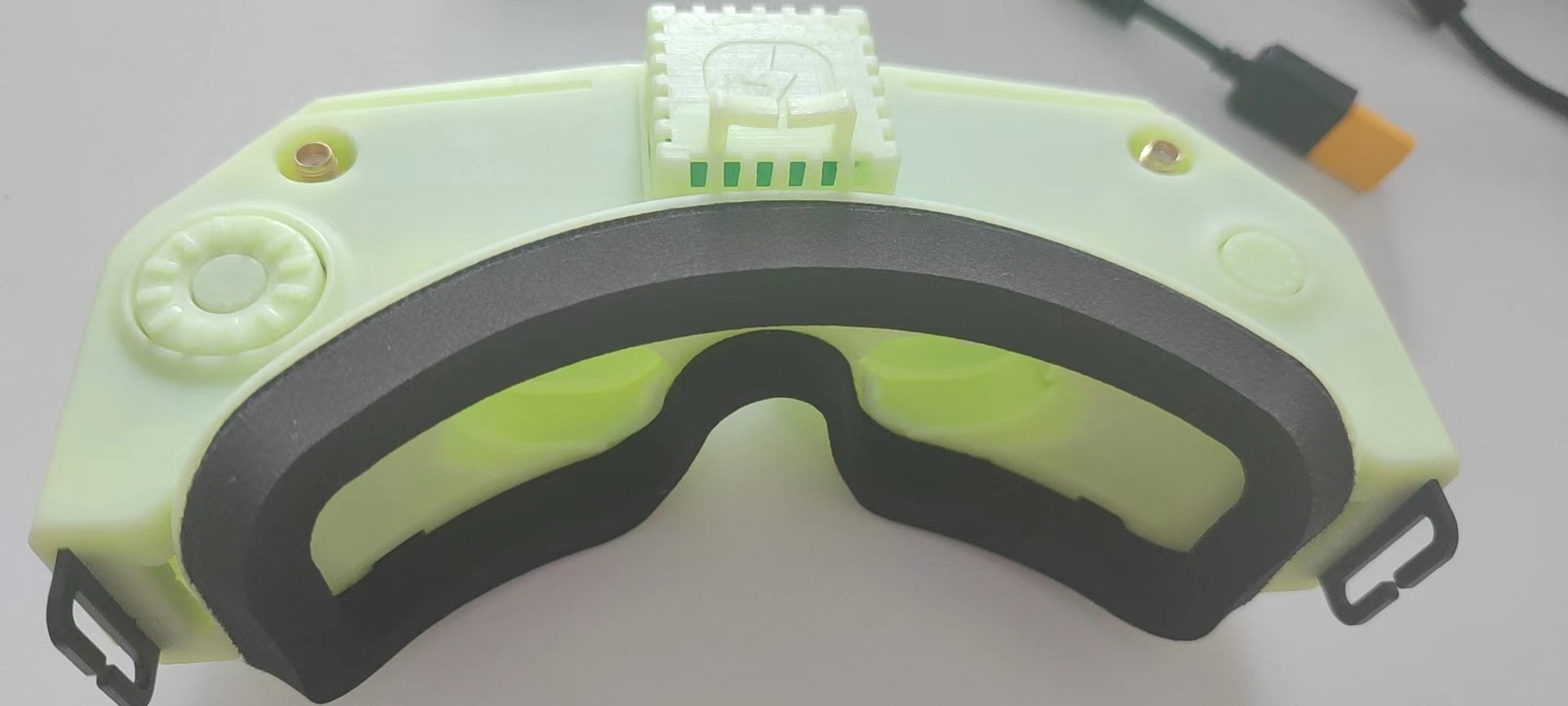
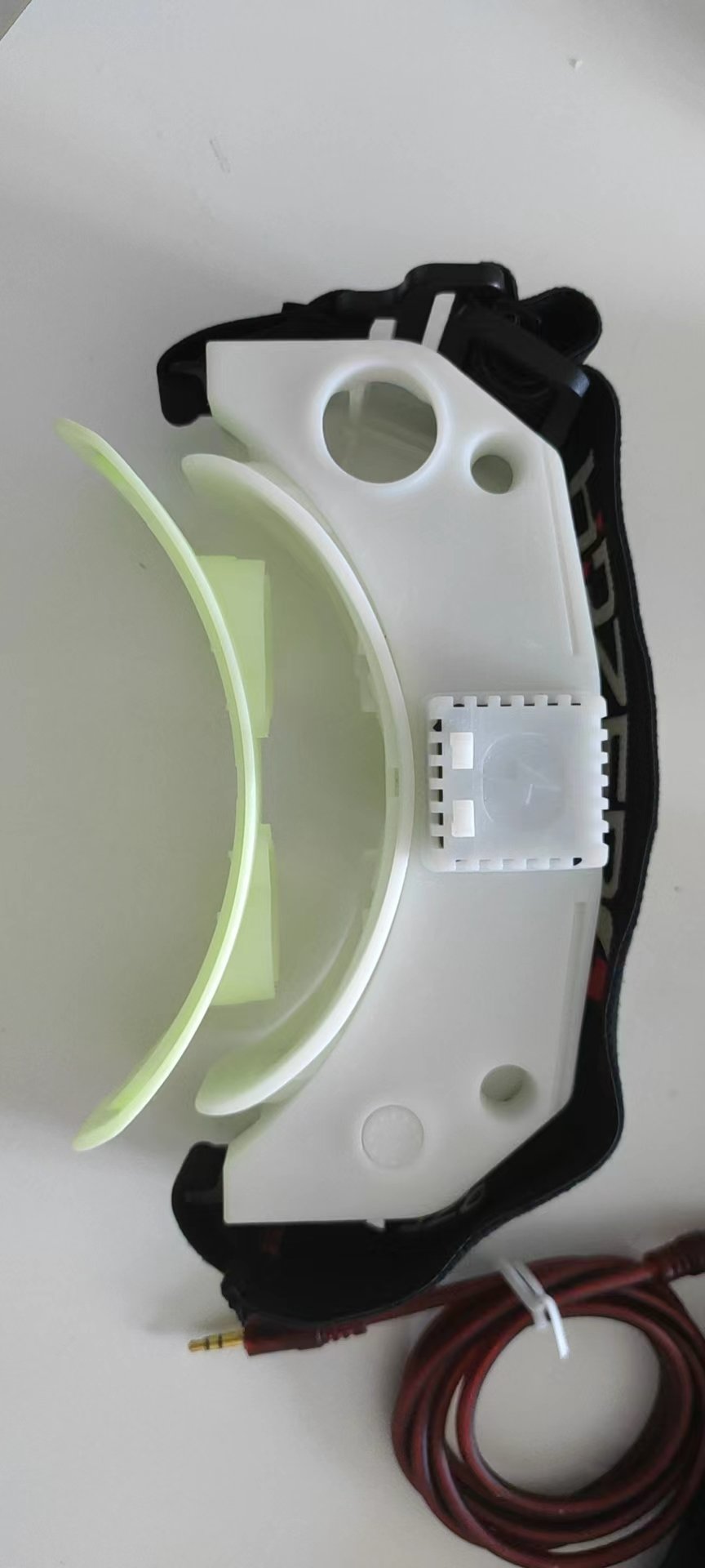
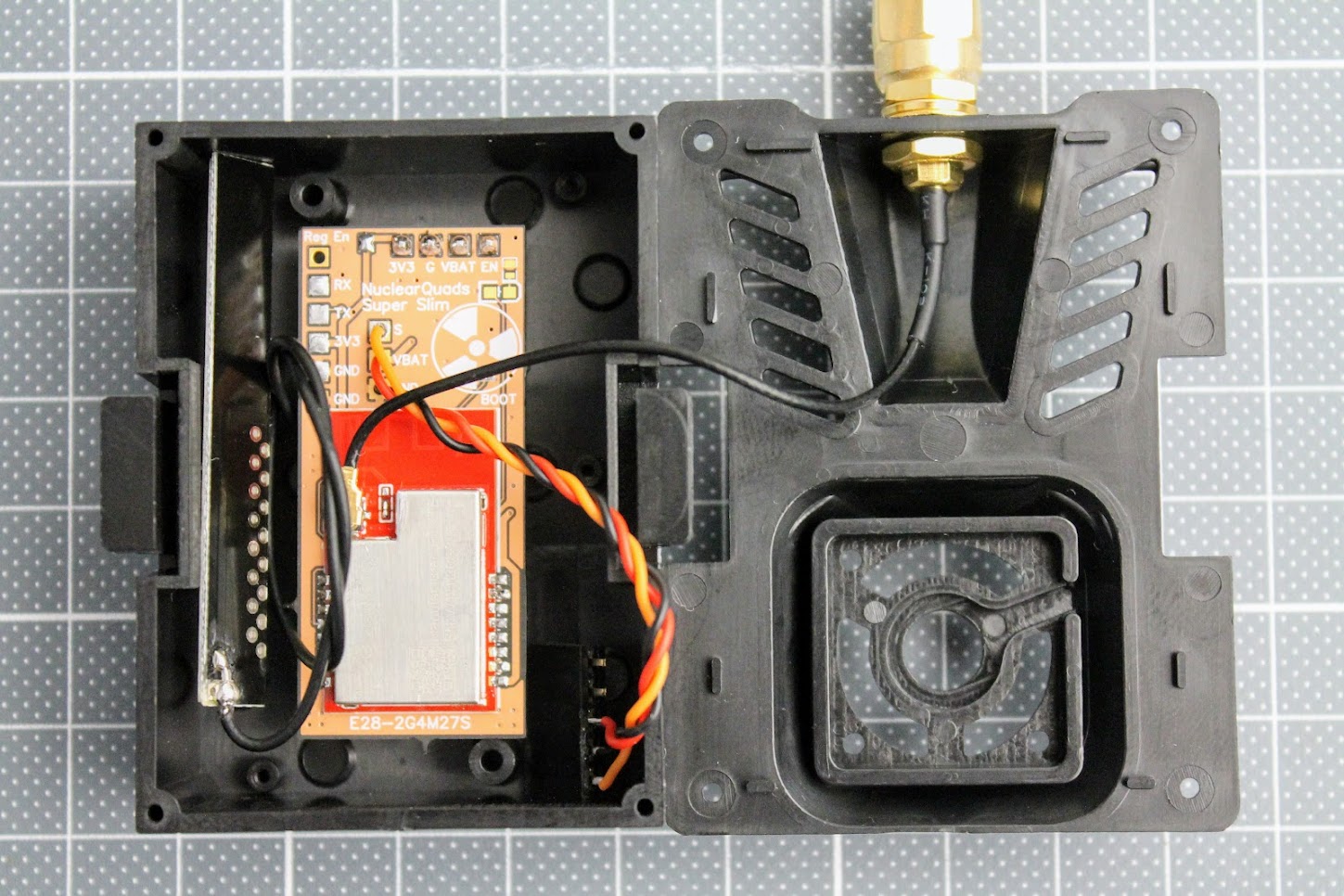
Nano sized DIY TX module can be installed in the full and nano size JR module case. It can be even installed inside the radio as it is really small.
TX Parts list
Parts list starts from PCB. I have ordered the PCB on OSH Park?(https://oshpark.com/shared_projects/K4feONmv).?The cost of PCB was $7.10?for?3pcs.
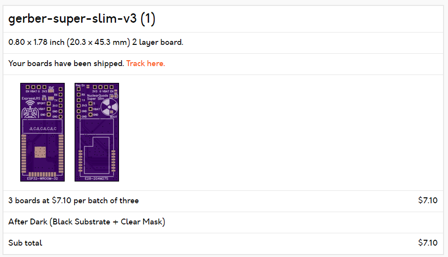
The original gerber files for PCB manufacturing can be found here:?
https://github.com/ExpressLRS/ExpressLRS-Hardware/tree/master/PCB/2400MHz/TX_SX1280_Super_Slim
I have purchased all the electronic parts from Aliexpress as it was the cheapest source.
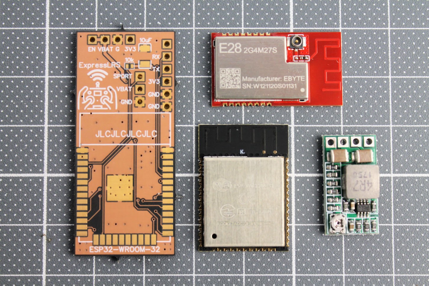
E28-2GM27S LoRa module (~$14) –?https://www.aliexpress.com/item/1005001812234542.html
ESP-WROOM-32? module (~$5) –?https://www.aliexpress.com/item/1005001833545594.html
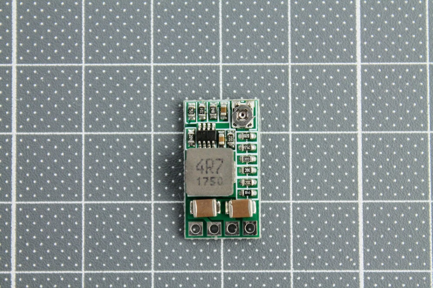
DC-DC power supply?module (~$2.5) – https://www.aliexpress.com/item/32880983608.html
SMA antenna pigtail (~ $0.5/pcs) –?https://www.aliexpress.com/item/4000848776660.html
Also you will need 10uF SMD capacitor (3528 or type B size) and the 10k?SMD resistor (0402 size).
Other things you will need: 5 pin 2.54mm header socket, silicone wires and of course a soldering iron set.
Build process
Soldered the ESP32-WROOM module and 10k resistor and 10uF capacitor. Soldering the resistor is the trickiest part as resistor is tiny (0402 size).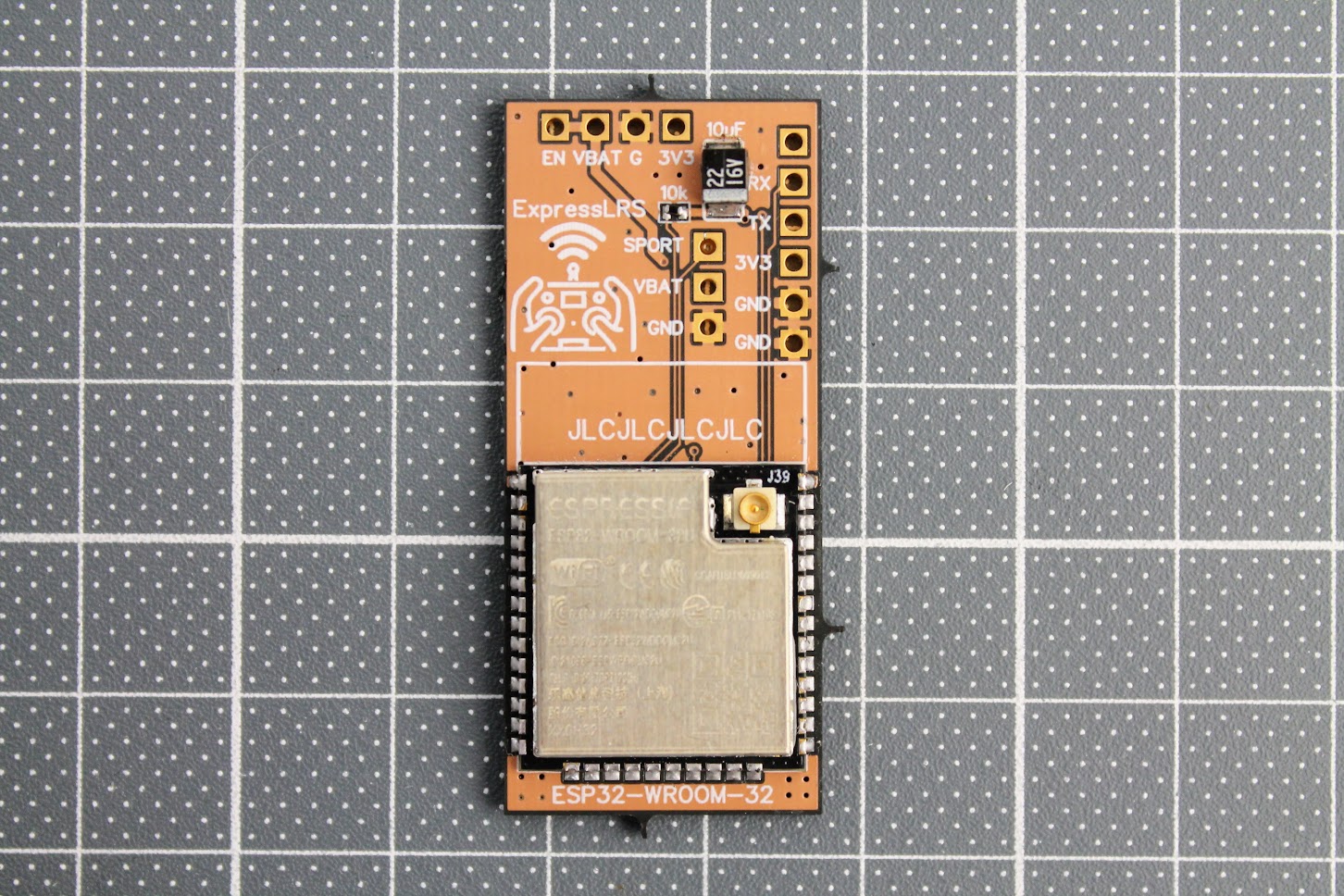
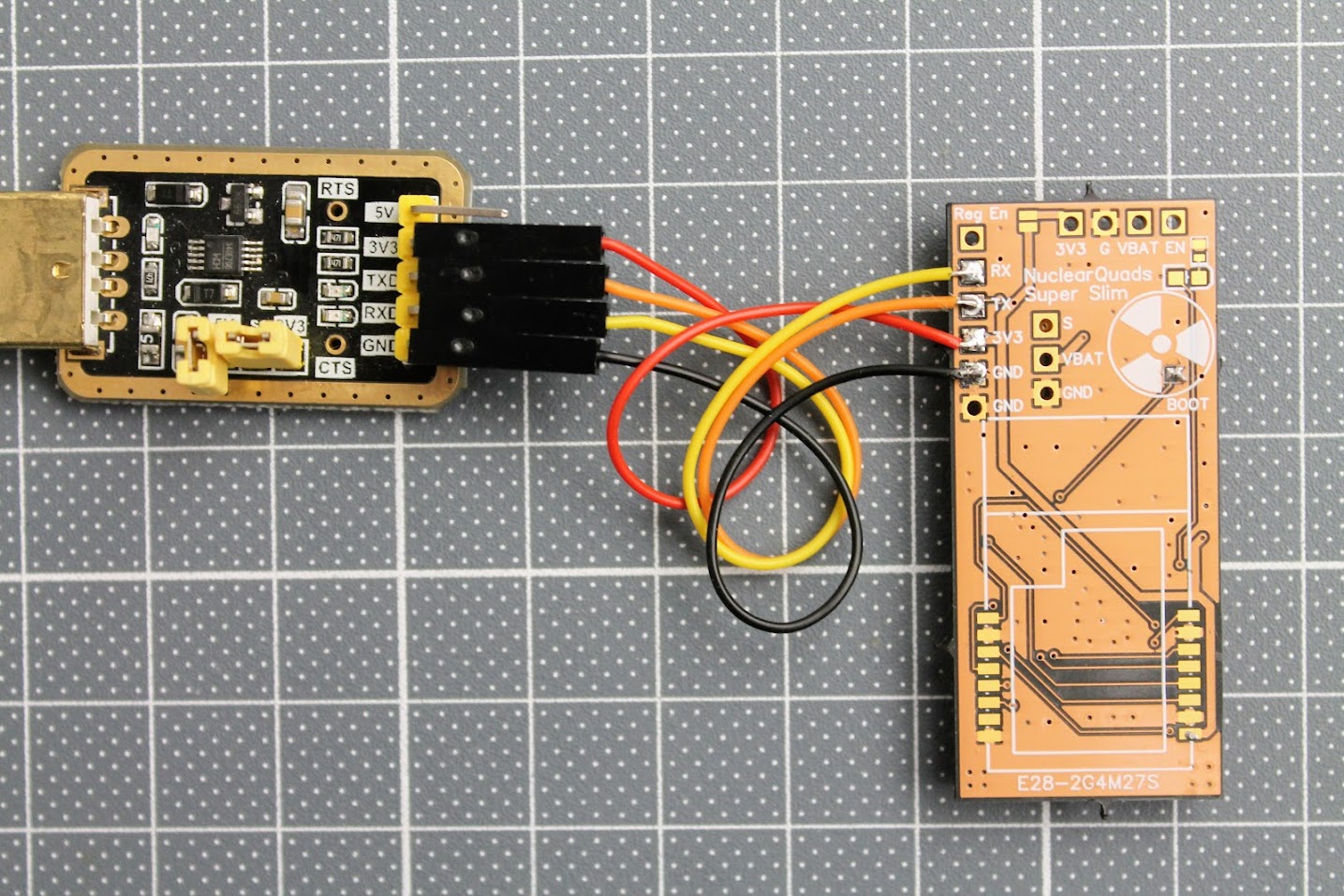
After the ESP32 module is soldered, you need to tempararily solder the RX, TX, 3.3V and GND wires. Connect these wires to the corresponding pins on the FTDI or any other USB to serial adapter. You can even use Arduino board. Don’t forget to short the BOOT pads for flashing the firmware by UART.
At this stage I would recommend to flash the ExpressLRS firmware to the ESP32-WROOM-32 module. For
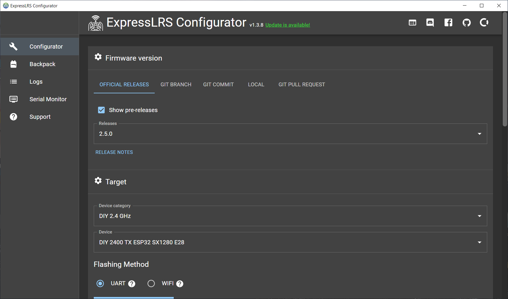
Start the ExpressLRS Configurator. You can download it from here:?https://github.com/ExpressLRS/ExpressLRS-Configurator/releases/?
Select “DIY 2.4 GHz” as Device category and “DIY 2400 TX ESP32 SX12800 E28” as Device.
Select UART as Flashing Method.
Read more about the flashing the ExpressLRS here:
ExpressLRS Open Source Long Range radio control system – Complete Guide
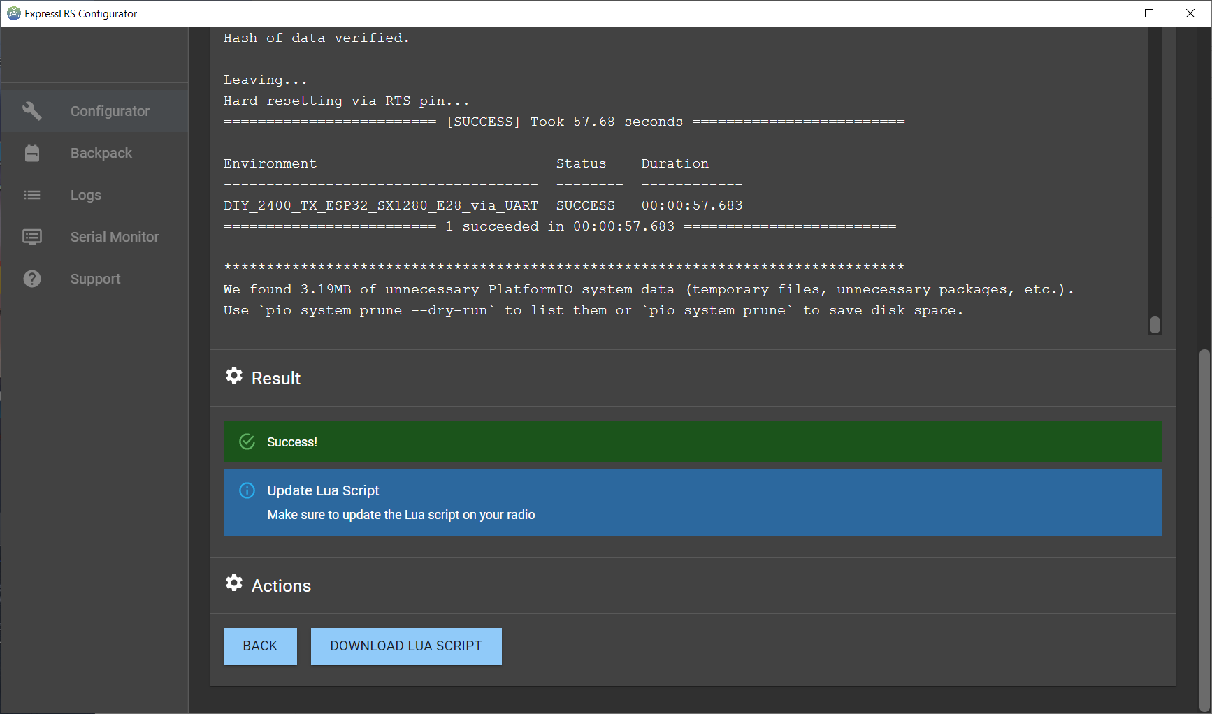
Press [Build & Flash]. Wait several minutes for it to compile.
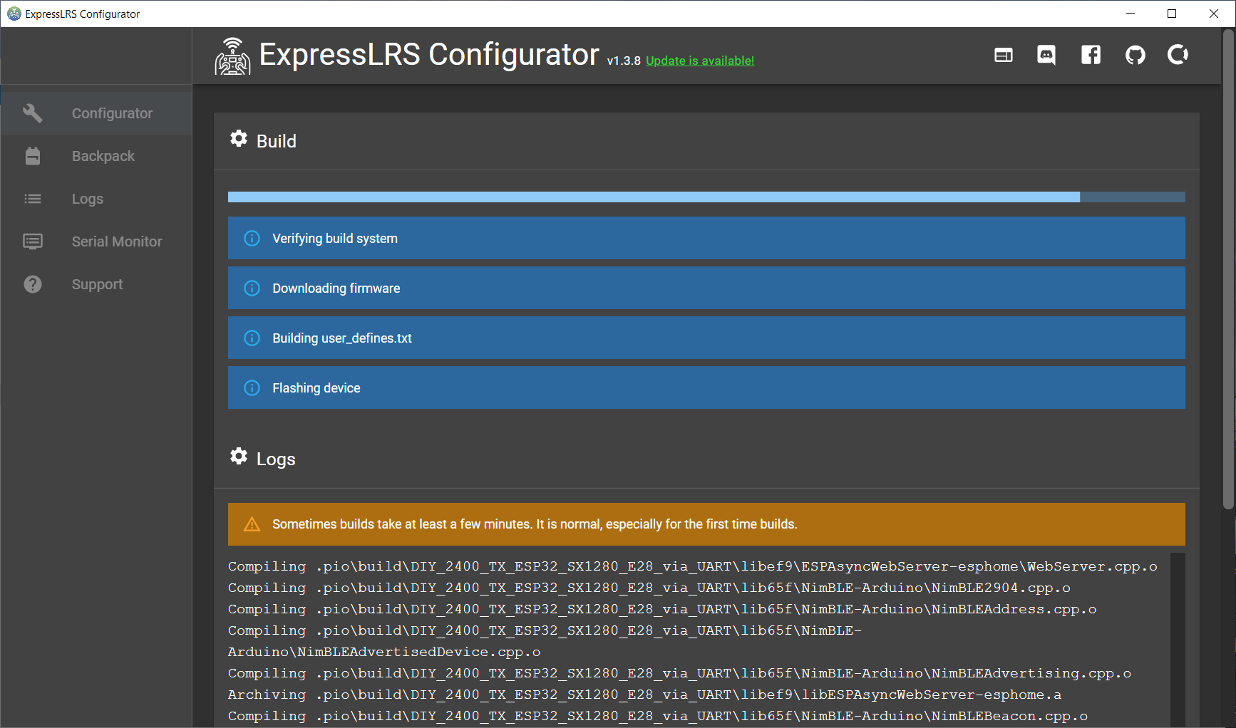
And flashing successful!
Now you can unsolder the FTDI (USB to Serial) adapter.
Next step solder the JR bay connector.
Prepare the power (voltage regulator) module. Short the 5V and 12V pads on the back side of the DC-DC regulator module. This will set the regulator to output the 3.45V, which is slightly more than 3.3V, but within the 5% tolerance of the modules.?
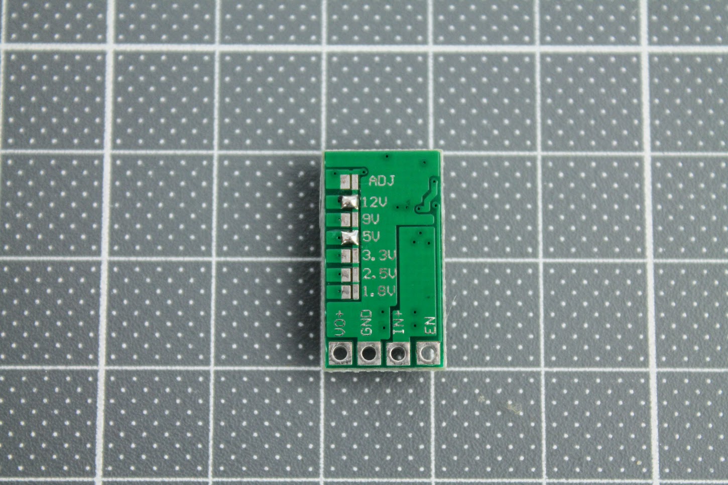
Turn the variable resistor to the clockwise end position (more about it below).
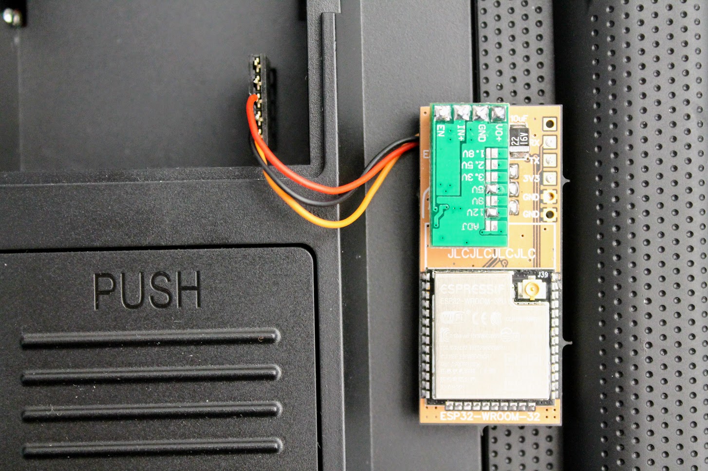
And solder the module to the EN, VBAT, G and 3V3 with the help of the pin headers.
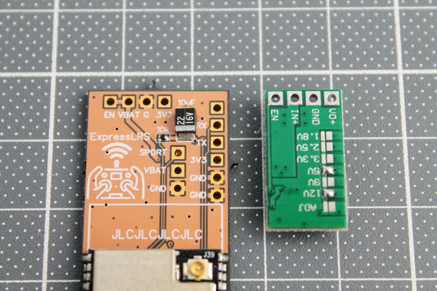
I also would like to suggest to connect the ExpressLRS module to the JR bay, power the radio, enable the External module in the model setup and measure the voltage between the GND and VO+ pads. It should be slightly more than 3.3V, the recommended voltage is 3.45V. In my case I have measured the voltage 3.58V, which is in the range of the absolute maximum voltage ratings (+10%) for the ESP32 and E28 modules, but its not recommended to operate the modules at this voltage, so I have turned slightly the dial on the variable resistor to set the 3.45V, which is 5% more than standard power voltage for modules. In theory E28 module should be happy to have a slight voltage overhead.
I need to notice, that at this point the ESP32 and E28 modules are not powered as the Reg En jumper pads are not connected.
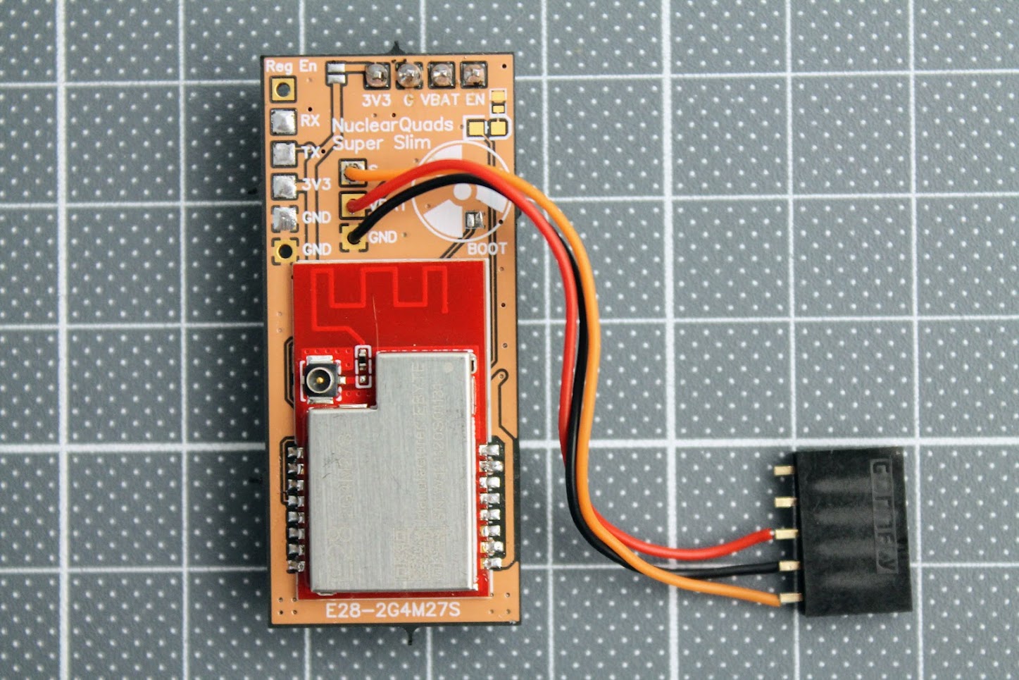
Once the power voltage is set and verified, you can short the?Reg En solder pads and solder the E28-2GM27S module.
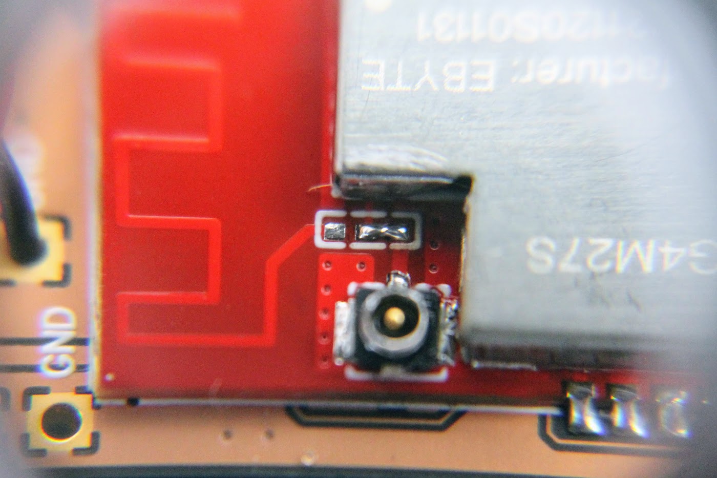
Another tricky part is to switch the zero Ohm resistor from the PCB antenna to the external (ipex) antenna position. I ended up just making the solder blob between the two pads as the resistor is zero ohms anyway.
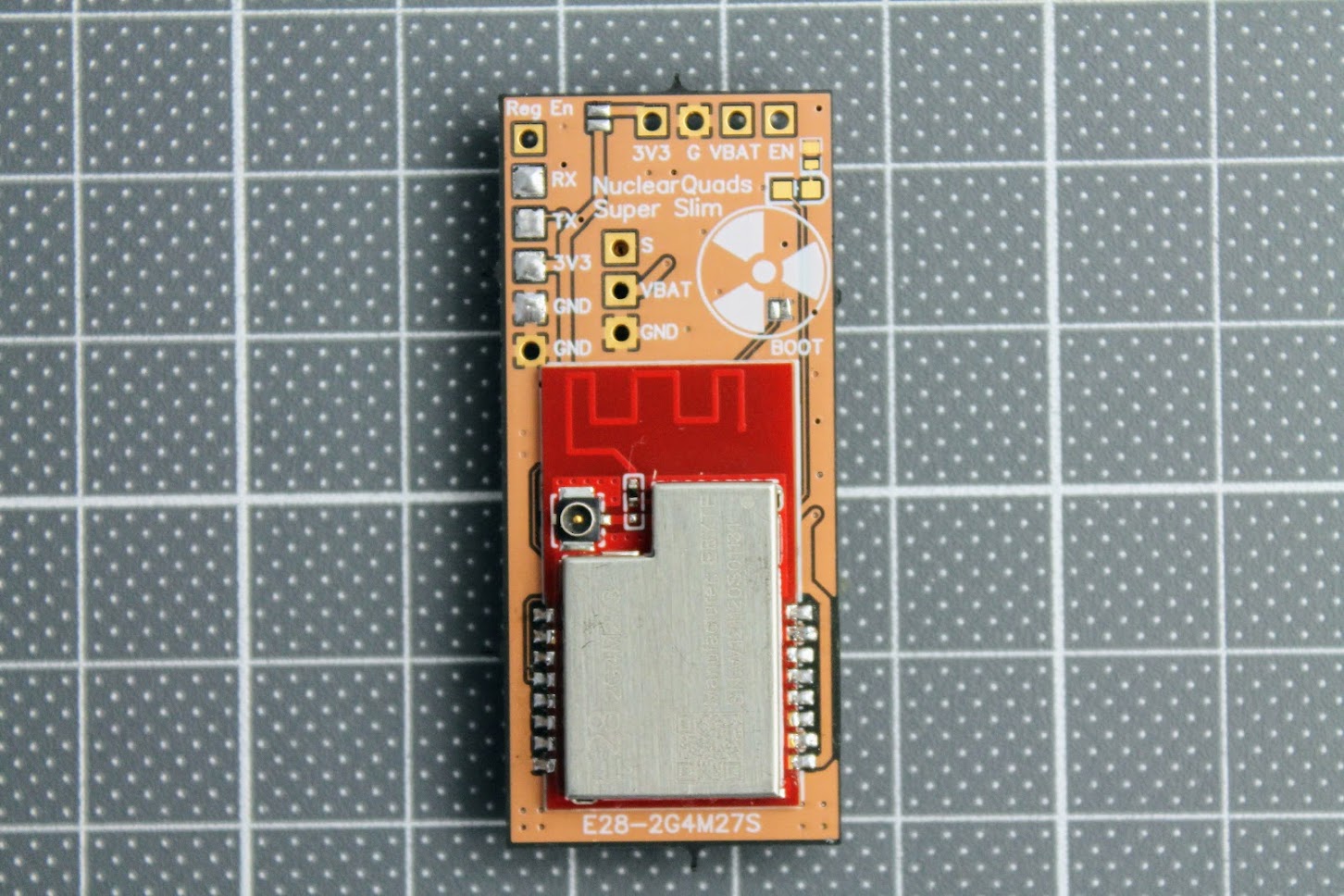
Completely assembled with all the antennas connected. Notice that 3.3V?power line Reg En jumper pads are soldered near the top right corner of the PCB board.
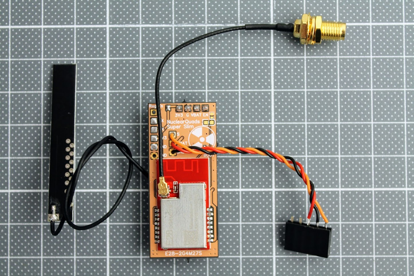
“Super slim” PCB variant of the ExpressLRS TX module fits easily in the JR case. Should also fit into the JR Nano case or even inside the radio as internal module.
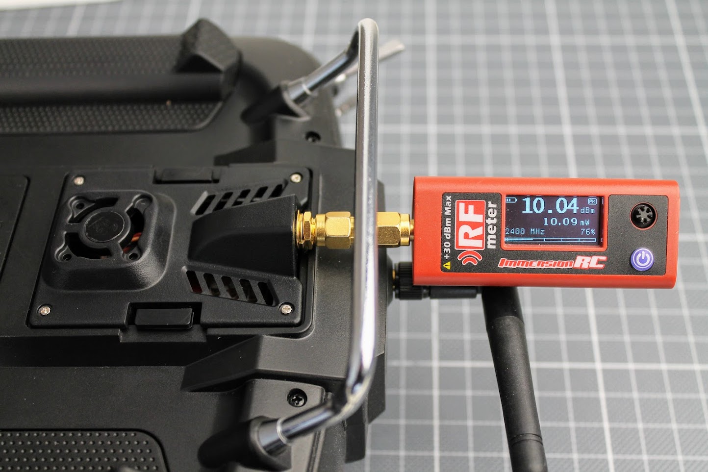
Power output tests
It is curious what RF power output does DIY ExpressLRS module gives. I have connected the ImmersionRC power meter to the antenna output of the DIY ExpressLRS module. The ExpressLRS module RF power output was set to 10mW, Dynamic power set to OFF. I’ve measured the exactly the 10mW of the power output.
At the 100mW output setting I’ve measured the 115mW output. 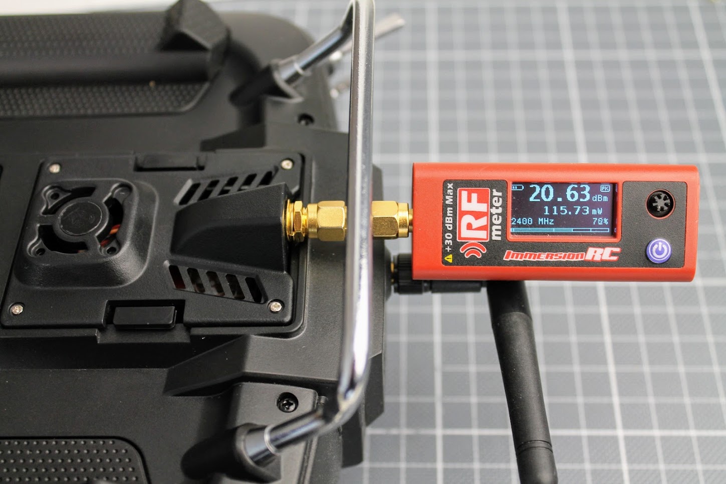
And at the 250mW?setting my RF power meter measured?255mW?of the RF output.?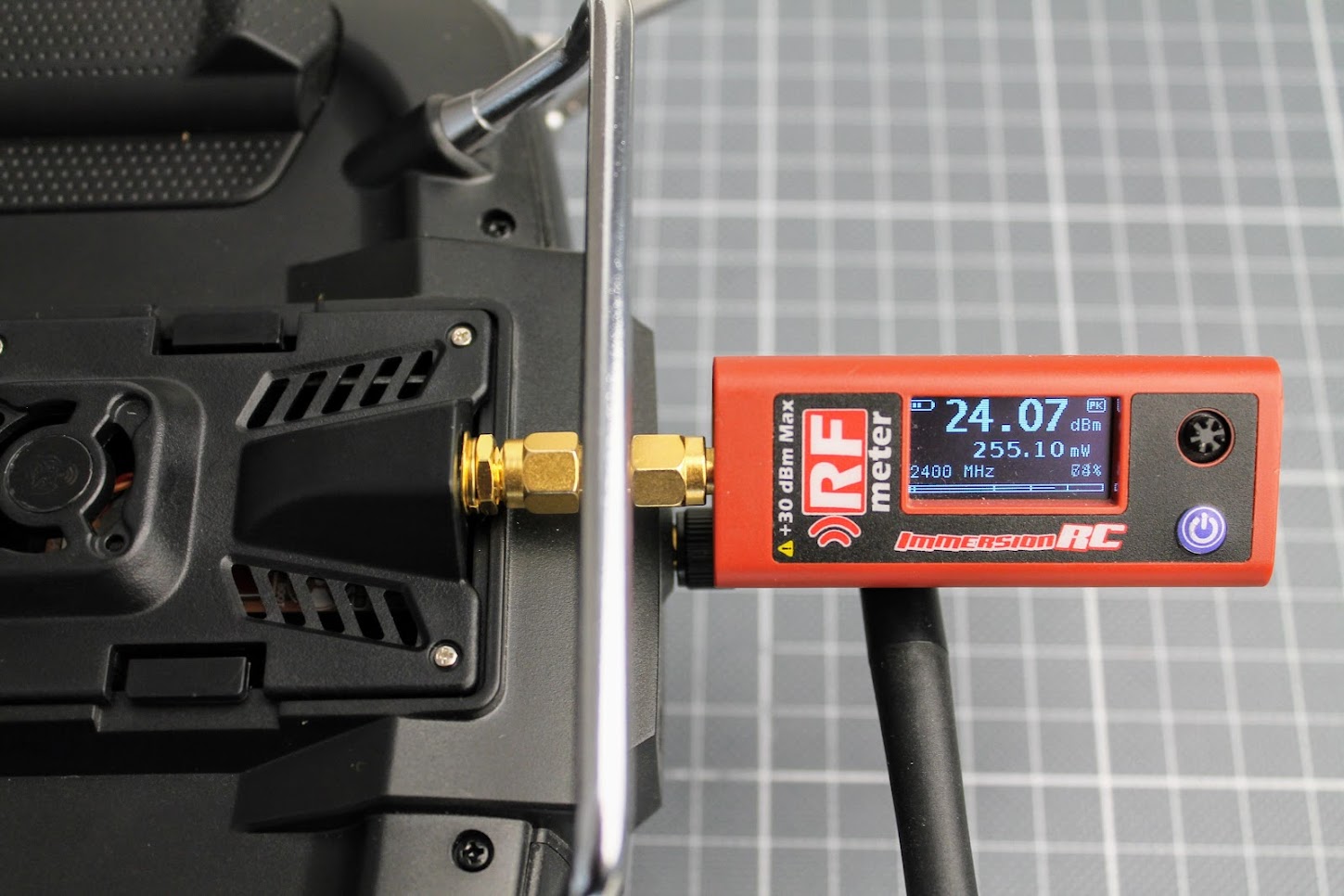
The 250mW output is stable, E28-2GM27S RF module does not heat up too much so no fan is needed.
?
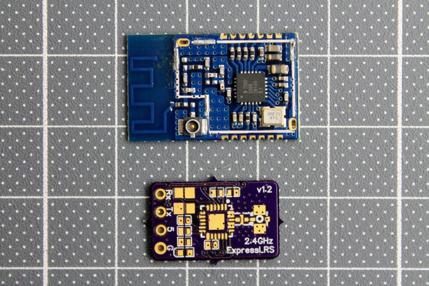
DIY ExpressLRS Nano Receiver
Remarks
DIY ExpressLRS Nano receiver uses 0402 size components. They are small as 1.0 x 0.5mm (0.040″ x 0.020″). It is almost impossible or at least it is very hard to solder these components without hot air gun. You will need proper equipment and soldering skills for soldering this small RX.
RX Parts list
I have ordered the PCB on?OSH Park?(https://oshpark.com/shared_projects/yYtMC9D3).?The cost of PCB was $3.00?for 6pcs. That’s $0.5 for one piece. Cheap as beans.
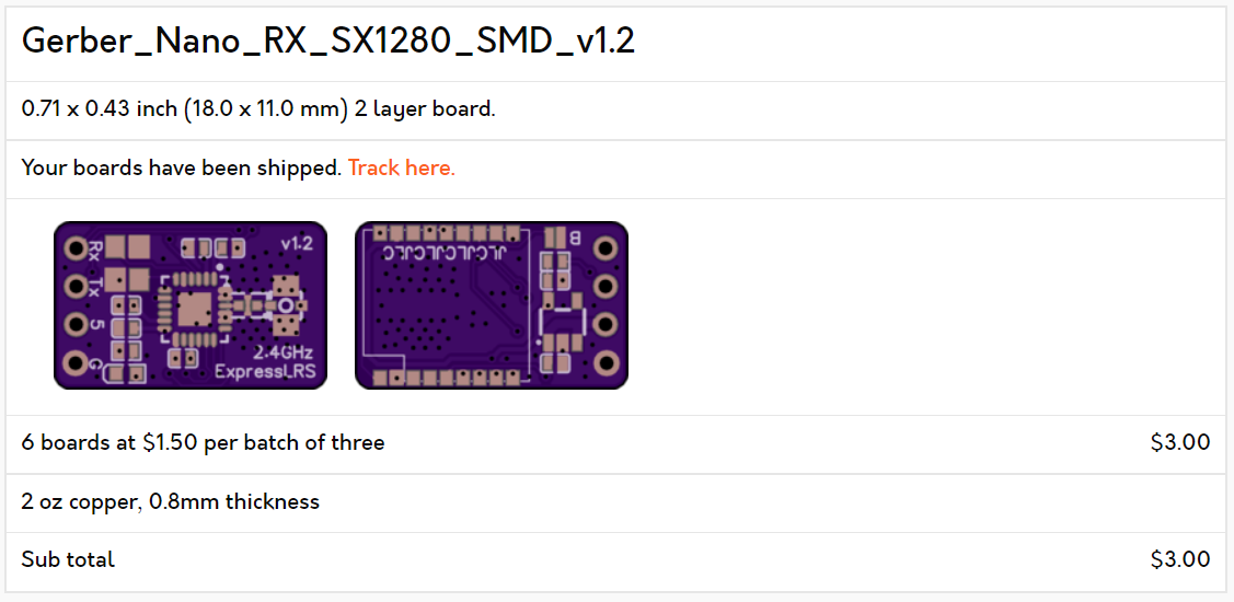
The original gerber files needed for PCB manufacturing can be found here: https://github.com/ExpressLRS/ExpressLRS-Hardware/…/PCB/2400MHz/RX_Nano
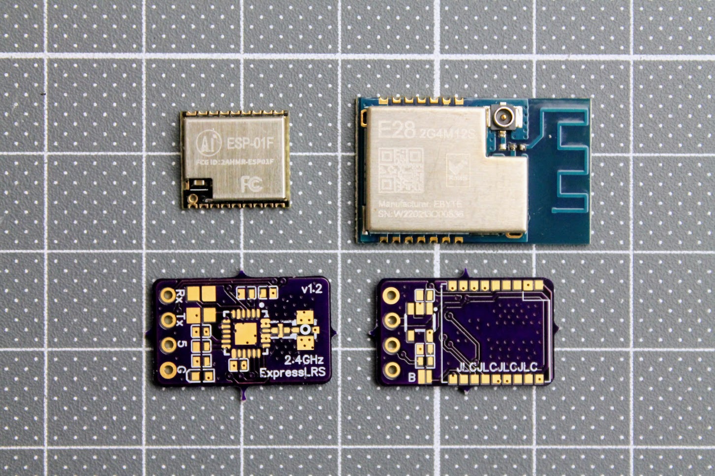
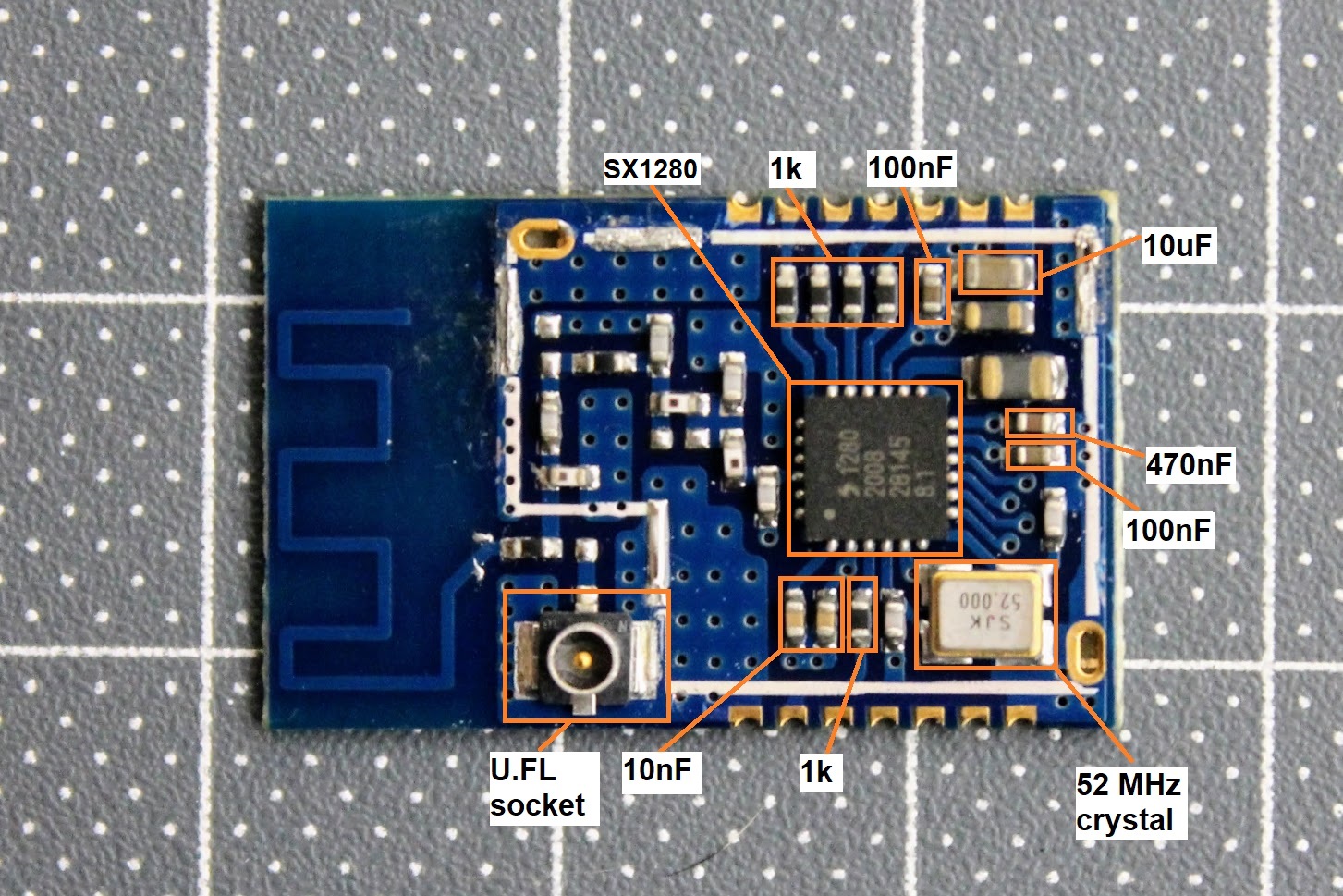
The EBYTE E28-2G4M12S module is used as the source for the cheapest SX1280 chip.?
EBYTE E28-2G4M12S on Aliexpress: https://www.aliexpress.com/item/1005001808615493.html
ESP-01F module – https://www.aliexpress.com/item/1005001808615493.html
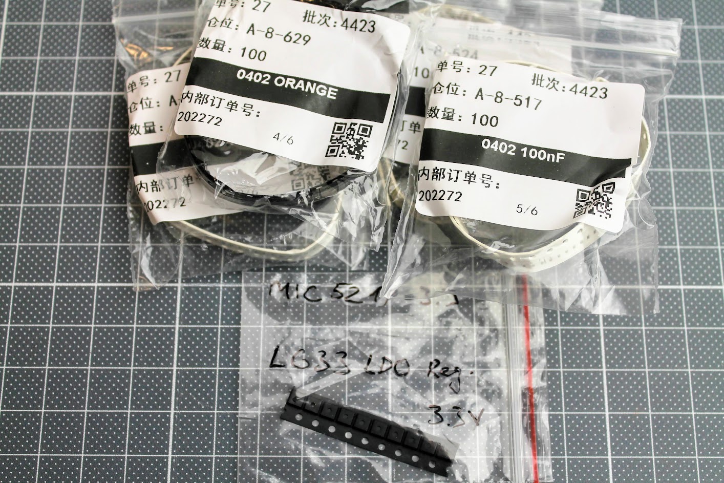
Some 0402 size components
De-cased EBYTE E28-2G4M12S module.
Here is the diagram of the EBYTE E28-2G4M12S module components for reuse in ELRS receiver.
The only other components you need to get are:
0402 size LED diode, 0402 size 1uF and 2.2uF capacitors
MIC5219-3.3 or MIC5319-3.3 voltage regulator – https://www.aliexpress.com/item/33047428186.html
ESP-01F module – https://www.aliexpress.com/item/1005001808615493.html
2.4GHz low pass filter (ballun) – 2450FM07D0034T or 2450FM07A0029T. These are harder to get. Look for it on Mouser or DigiKey.
You will definitely need the RX antenna also.
Build process
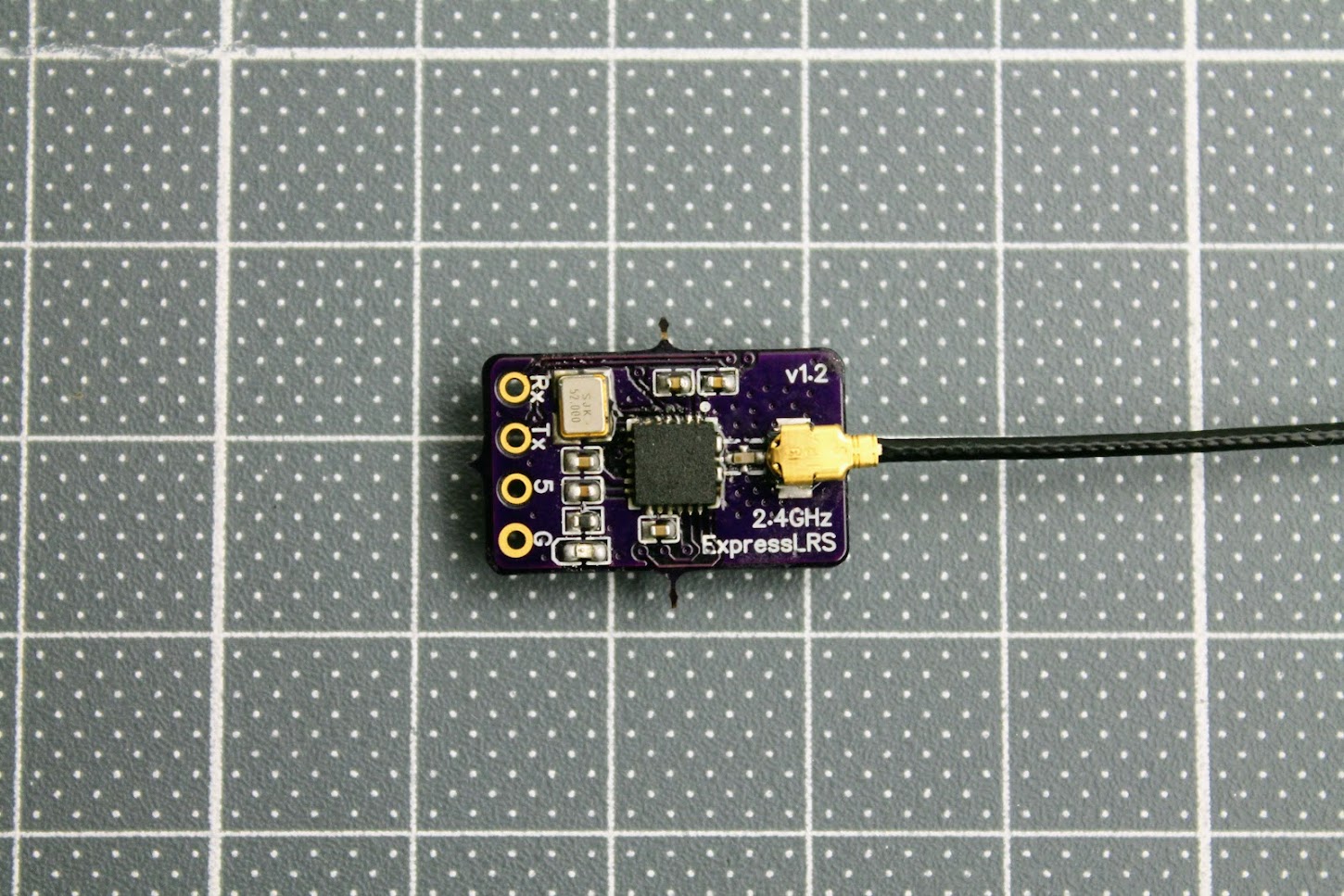
The PCB and the components are so tiny, that you need definitely need the magnifying glass, hot air soldering gun, precision tweezers and SMD soldering paste. You will have to apply the soldering paste, place the SMD components on the back side of the receiver first, solder them with a help of hot air gun and then repeat the same on the top side of the receiver.
Photos of the soldered DIY ELRS Receiver.
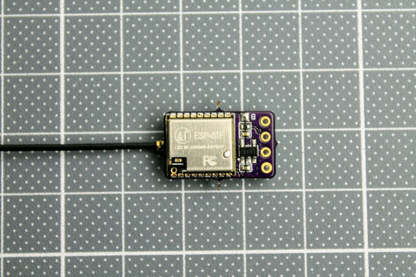
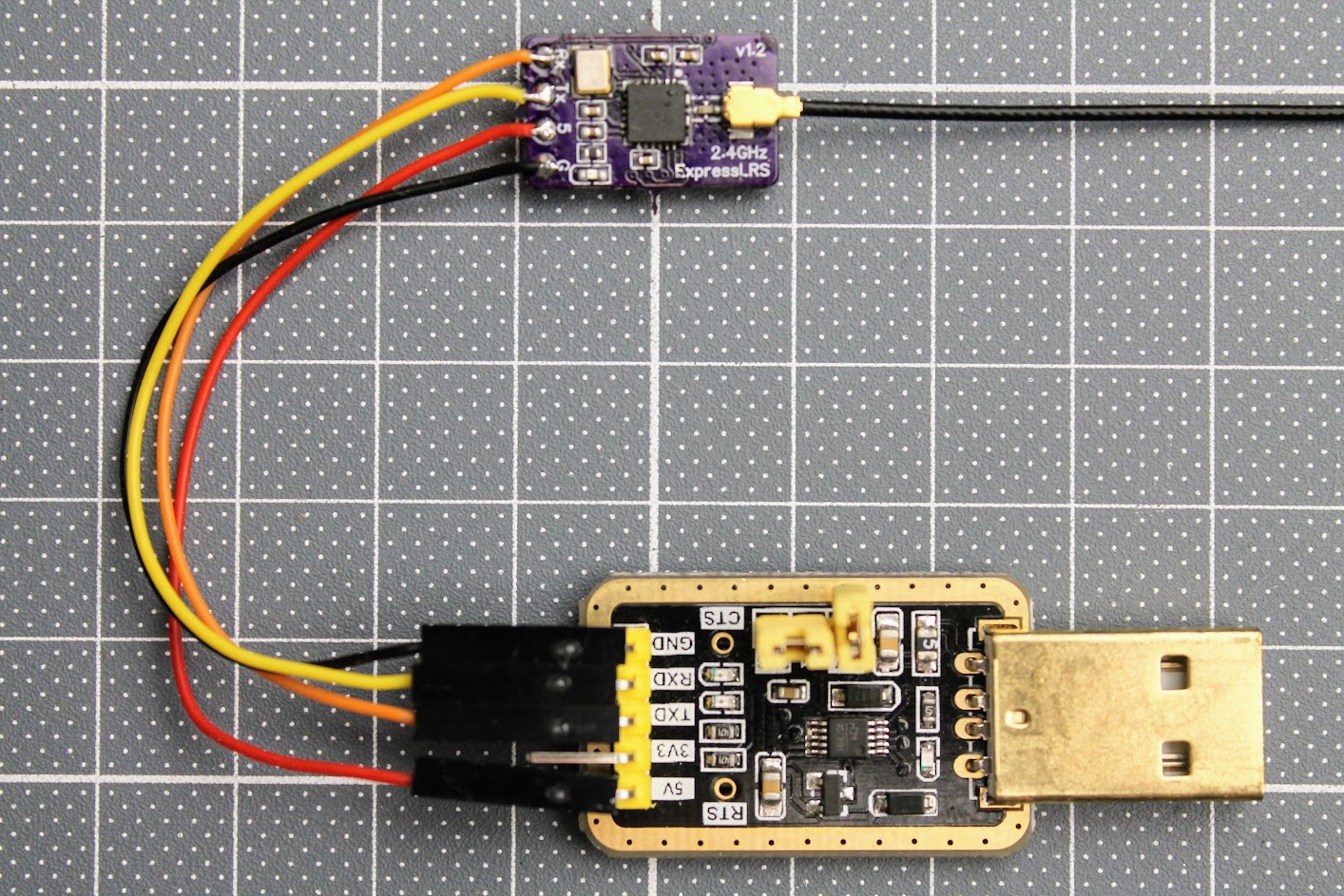
After the ESP-01F module is soldered, you need to solder the RX, TX, 3.3V and GND wires. Connect these wires to the corresponding pins on the FTDI or any other USB to serial adapter. You can also use Arduino Uno board for USB to serial adapter. Don’t forget to short the BOOT pads on the RX board for flashing the firmware by UART.
Read more about the flashing the ExpressLRS here:
ExpressLRS Open Source Long Range radio control system – Complete Guide
DIY ExpressLRS receiver ready for flashing.
Making the ExpressLRS transmitter and receiver by yourself is definitely a fun task, however you should evaluate your skills of the SMD soldering in case of the making the super small receiver.
]]>