Hardware
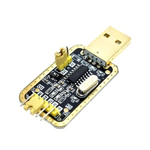
USB to TTL adapter. Better get one with 3.3V option. I have tested the cheap CH340G adapters and they work flawlessly, therefore I recommend them.
(Possible variants on ebay: https://www.ebay.com/sch/i.html?_nkw=USB+to+TTL+CH340G+3.3V)
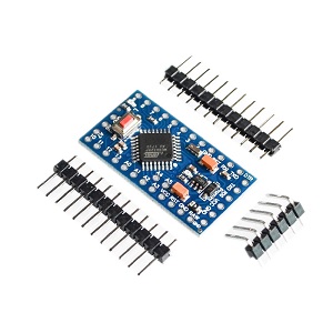
Arduino Mini Pro with Atmega328P. Probably any Atmega328 based Arduino board should fit, just have in mind that we need 3.3V power supply and logic levels.
(possible variants on ebay:?https://www.ebay.com/sch/i.html?_nkw=Arduino+Mini+Pro+atmega328)
Software
You can download all the software in one package here:?http://bit.ly/Google-Drive-Caddx-Turtle-Firmware-Flashing?or you can download the individual packages from the list down below:
-
- Flashrom programming utility (https://www.flashrom.org?). If your PC runs on Windows then I recommend to download already compiled windows version here:?http://ra.openbios.org/~idwer/flashrom/mingw/?(Edit: link seems to be dead now, but we have it saved on Internet Archive: https://web.archive.org/web/20181112215901/http://ra.openbios.org/~idwer/flashrom/mingw/)
- XLoader to upload binary file to Arduino board (http://russemotto.com/xloader/?) (alternative link:?http://www.hobbytronics.co.uk/download/XLoader.zip)
- Arduino firmware [frser-duino.hex] (download link:?https://drive.google.com/file/d/0BxZ43kLDo-GFOWJnQ19HYWVZVmc/view)
- Caddx Turtle firmware flash dump file [flash.hex] (download link: https://bit.ly/Goggle-Drive-Caddx-Turtle-Firmware-Dump-files)
Note! It seems that the Caddx has changed the Turtle Cam sensor board for the latest batches and you should pay attention what firmware you are uploading. There are two firmware files: for old sensor board and the new sensor board. The provided firmware may not work for particular your version of Caddx Turtle. Do the firmware backup!
Procedure step by step
First you need to flash Serprog firmware to Arduino Mini Pro:
- Connect USB – TTL converter to Arduino Mini Pro board
- If everything is ok, You should see “FTDI” or “USB-SERIAL CH340” device in device manager
- Connect Arduino Mini Pro to USB-TTL adapter (check that your FTDI or USB Serial adapter uses 3v for powering)
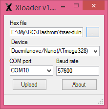
- Start Xloader, open [fser-duino.hex] file, set the? COM port and hit “Upload” (tip: Press and hold Reset button on the Arduino board and release right before you hit the “Upload” button).
Now You have Flashrom compatible programmer.
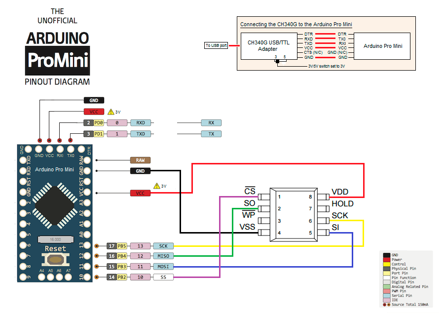
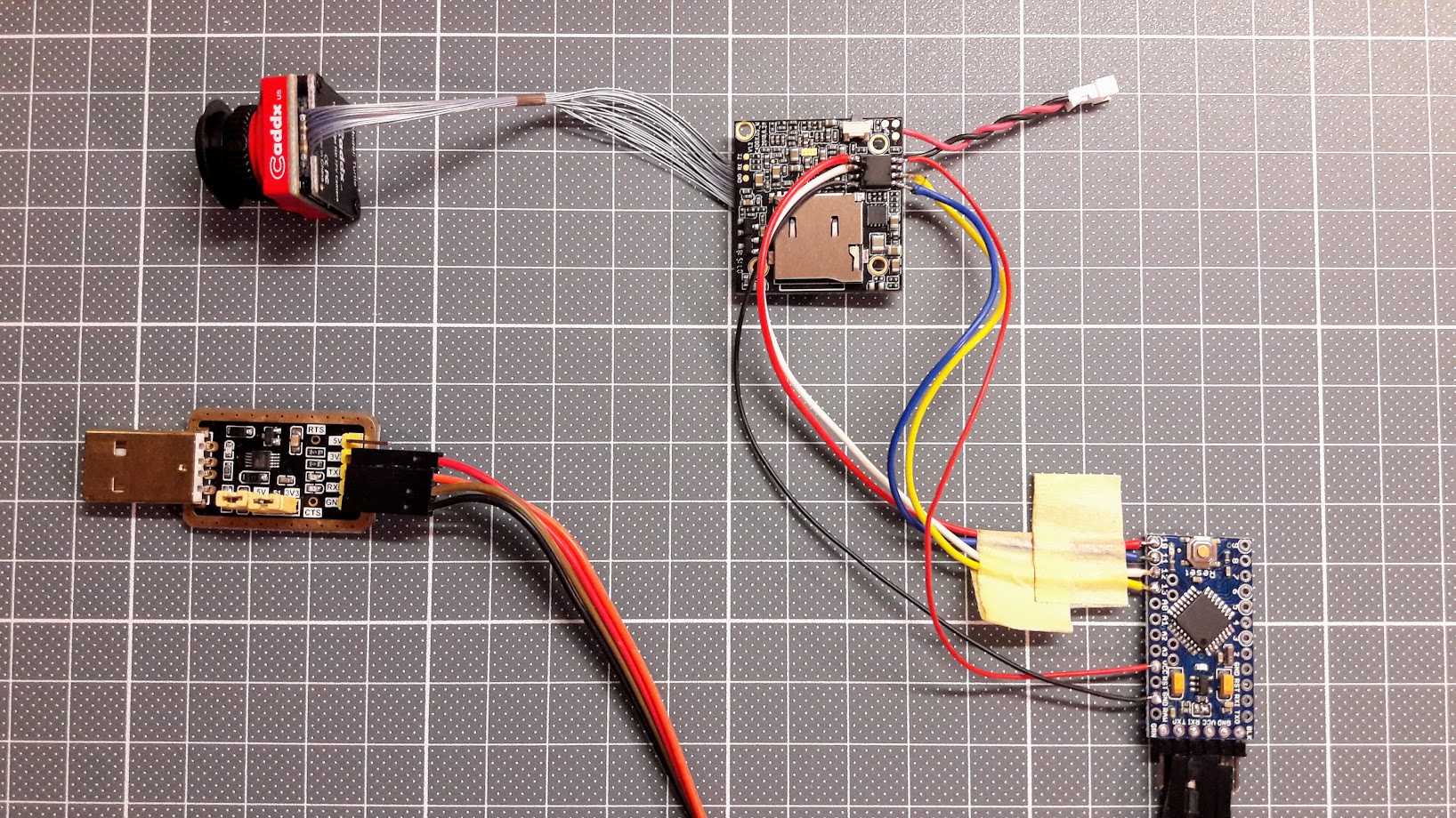
Connect the Turtle serial flash IC to the Arduino. Use supplied connection schematic. Solder 6 wires: VCC, GND, CS, CLK, MOSI and MISO.?Try to keep them as short as possible, better about 10cm. Use small diameter wire.
Connection table:
| FLASH CHIP | ARDUINO BOARD |
|---|---|
| VCC (pin 8 ) | 3.3V output (5V can kill the board!) |
| GND (pin 4) | GND pin |
| CS (pin 1) | pin 10 |
| MISO (pin 2) | pin 12 |
| MOSI (pin 5) | pin 11 |
| Clock (pin 6) | pin 13 |
Connection schematic:
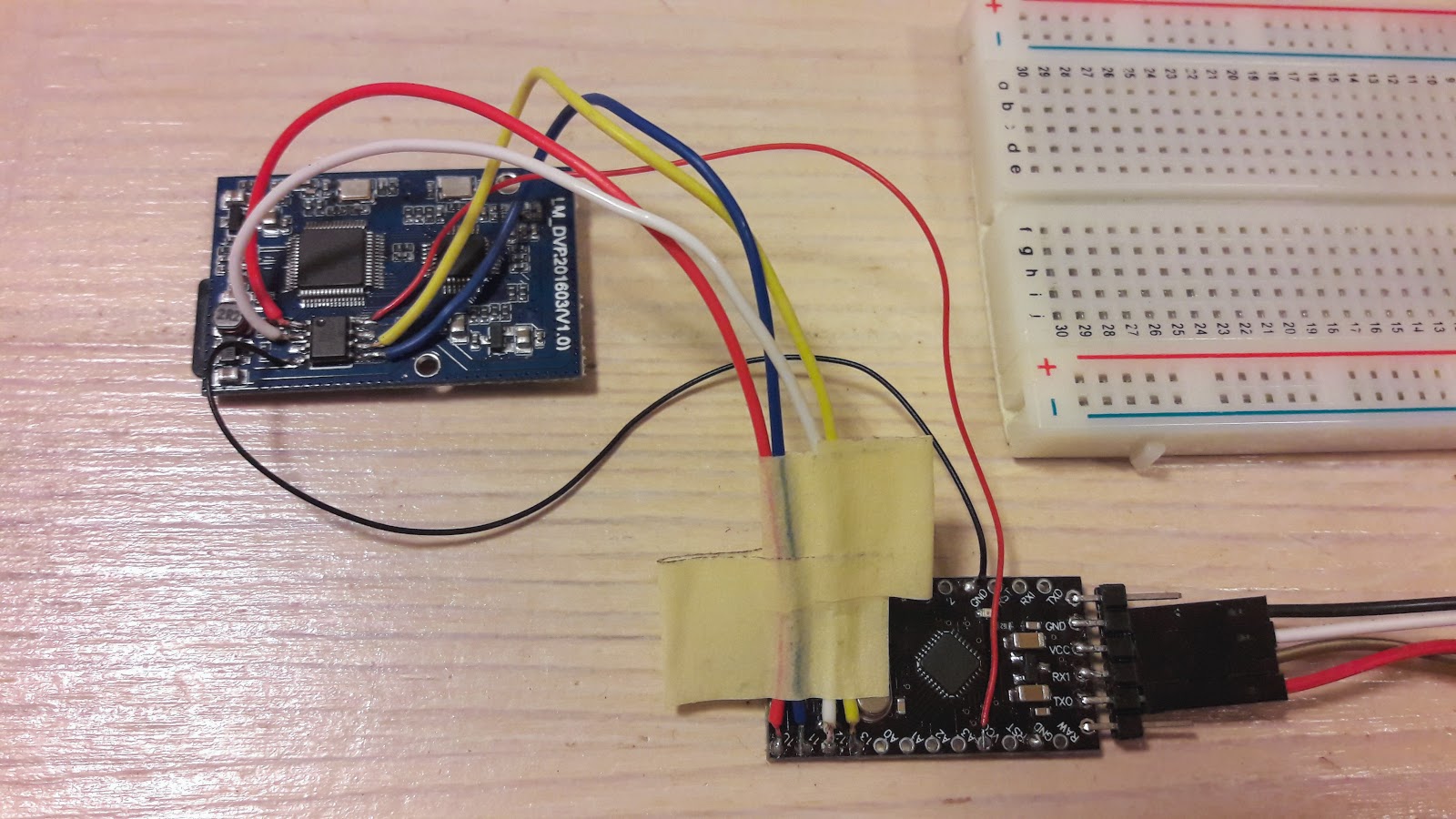
Caddx Turtle Flash chip connected to the Arduino board should look like that:
Do not power the Caddx Turtle board with alternative power source. It should be left only connected to Arduino board.
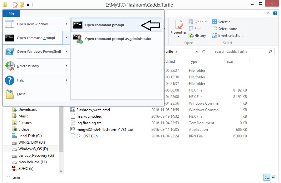
Once you have everything connected, try reading the contents of flash IC by running this command in Windows Command prompt:
mingw32-w64-flashrom-r1781.exe --programmer serprog:dev=COM7:115200 -c MX25L6445E --read test.hex
Here in the parameter?--programmer serprog:dev=COM7:115200?change COM7 to whatever COM number your USB-TTL adapter has.
You should get similar output to this:
E:\My\RC\Flashrom\Caddx.Turtle>mingw32-w64-flashrom-r1781.exe --programmer serprog:dev=COM7:115200 -c MX25L6445E?--read test.hex

flashrom v0.9.7-r1781 on Windows 6.2 (x86)

flashrom is free software, get the source code at http://www.flashrom.org
Calibrating delay loop... OK.

serprog: Programmer name is "frser-duino"

Found Macronix flash chip "MX25L6445E" (8192 kB, SPI) on serprog.

Reading flash... done.
Be patient – reading 8Mbytes of the data takes ~ 10 min.
If everything goes OK by this far, you are ready to flash the firmware. To flash the device, start this command:
mingw32-w64-flashrom-r1781.exe --programmer serprog:dev=COM7:115200 -c MX25L6445E --write flash.hex
You should get similar output to this:
E:\My\RC\Flashrom\Caddx.Turtle>mingw32-w64-flashrom-r1781.exe --programmer serprog:dev=COM7:115200 -c MX25L6445E?--write flash.hex
flashrom v0.9.7-r1781 on Windows 6.2 (x86)flashrom is free software, get the source code at http://www.flashrom.org?
Calibrating delay loop... OK.
serprog: Programmer name is "frser-duino"

Found Macronix flash chip "MX25L6445E" (8192 kB, SPI) on serprog.
Reading old flash chip contents... done.
Erasing and writing flash chip... Erase/write done.
Verifying flash... VERIFIED.
Note: Flashing 8Mbytes of the data takes a lot of time – be patient. Arduino flashing device uses slow SPI connection with 115200 baud rate. (approx 14kb per second, or 840kb per minute) so it takes about 10 min to read, 20 min to erase-write and 10 min to verify…
Note: Caddx Turtle can not boot normally while the Arduino board is connected. Options – you can disconnect the wires after the flashing or you can hold the reset button on the Arduino board while the Caddx Turtle is booting to check if everything is working after the flash process.
Note: Windows command prompt can be opened by selecting the File – Open command prompt from the file explorer menu.
You are done! You have successfully restored the firmware.
If you have questions or you need more details, then leave a comment below.
Mandatory disclaimer: Do it on your own risk. Flashing the firmware can result in bricking your device.
]]>List of parts
Everything you will need is Arduino Pro Micro board and any Flysky, Frsky or any other RC receiver compatible with your transmitter. Arduino Pro Micro can be purchased from Sparkfun, but there are a lot cheaper cloned boards on Ebay, Aliexpress or Amazon (Possible compatible boards: http://bit.ly/Aliexpress-Arduino-Atmega32U4, http://bit.ly/EBay-Arduino-Pro-Micro) . Actually almost any Arduino board with Atmega32u4 should work. Including Arduino Leonardo.
Actual parts costed $3.40 for Arduino Micro Pro board and $6.99 for iRangeX Flysky receiver. So the total price was $10.69.
You can choose the cheap and small receiver from Flysky receivers list and from Frsky receivers list.
The code is written by GregNau and original project is on GitHUB. Project was intended for Sparkfun Pro Micro board, cause it is based on ATmega 32U4 which can act as a game controller on USB. Although it should compile fine on other '32U4' boards also (eg. Leonardo, ProMicro).
I had a problem with my computer (64bit Windows 8 and Windows 10) not detecting arduino as HID Joystick, so I have modyfied the source to make the dongle work. My slightly modyfied Arduino project source code for RC simulator Dongle can be downloaded from here: http://www.dzskam.com/go/arduino-rc-simulator-dongle-project-files
Compiling requires Arduino IDE v1.8.2 at least and 2 external libraries:
Make sure these are installed properly before compiling, otherwise it will instantly fail. Both them have clearly detailed instructions about installing in the README.md file of the each project.
For your convenience, you can download all the three packages from here: http://www.dzskam.com/go/arduino-rc-simulator-dongle-drive-folder/
Schematics
The connection schematics is very simple, If you will use a receiver with PPM output, then you’ll only need to connect PPM out on receiver to D4 on Arduino board, +5 to VCC and GND to GND:
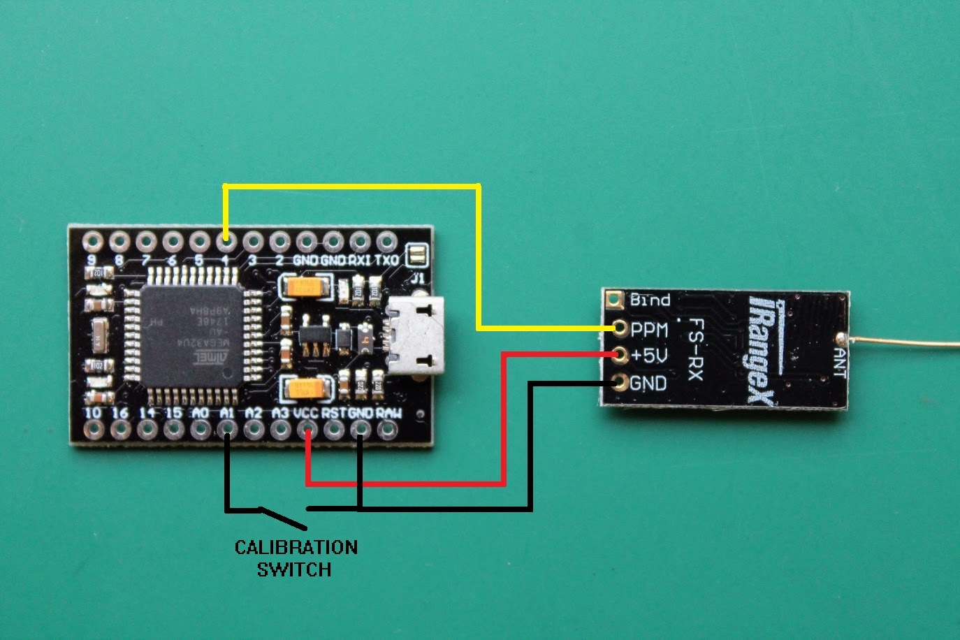
There is also an alternative Calibration Swith, connecting GND and A1 pin on the Arduino board. Calibration switch can be used for triggering the transmitter sticks/switches calibration. Actually the first time you power the Arduino with a RC simulator dongle firmware it triggers the calibration automatically so I’ve never needed this swich so far.
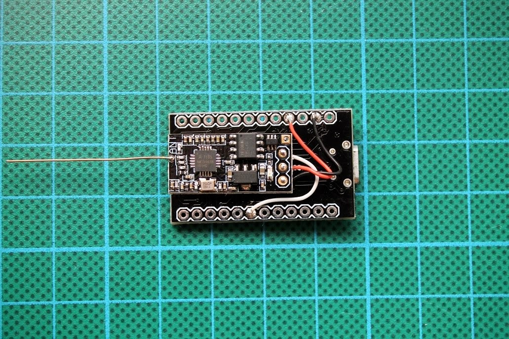
My soldered receiver to the Arduino board:
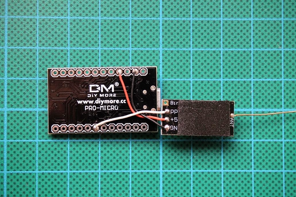
Attached it to the back of the arduino board with dual side adhesive tape:
You can also wrap the dongle into heat shrink to make it safe from accidental shorting of the electronics.
Installing the drivers for Arduino board
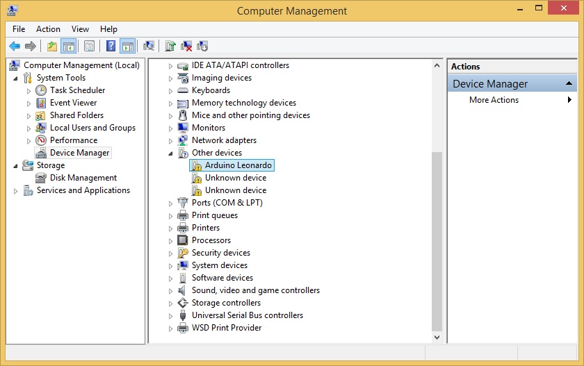
First time you connect the Arduino Pro Micro board (Arduino leonardo) it will show up as device without drivers:
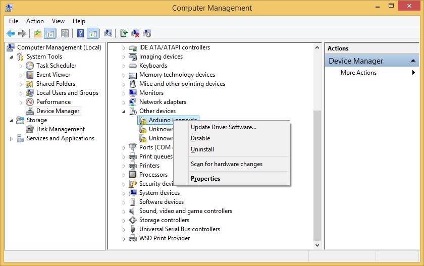
You need to right click on the device and select “Update Driver Software…”
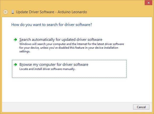
Choose “Browse my computer for driver software”
If you already have installled the Arduino IDE software, then the drivers should be in YourDriveLetter:\PathToArduinoFolder\Arduino-1.x.x\drivers\ folder
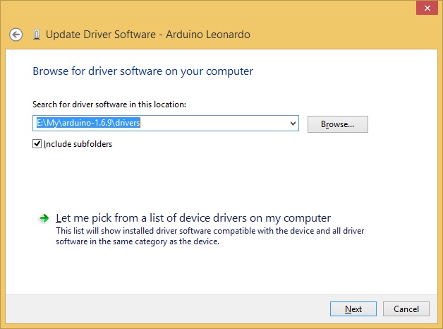
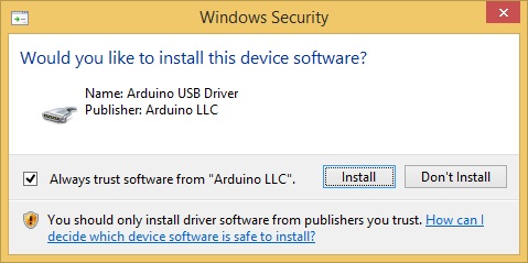
Select that you trust the Arduino Software and [Install]:
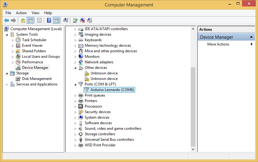
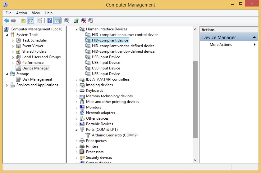
After the driver is sucessfully installed, you should see the Arduino Leonardo as Port device.
Flashing the code to Arduino
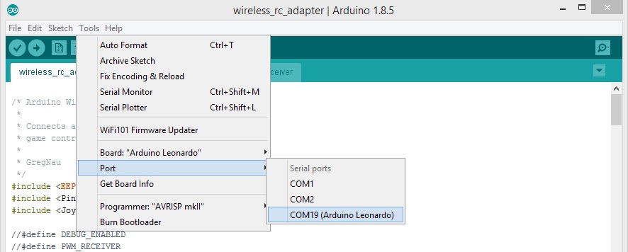
Open the wireless_rc_adapter.ino project in Arduino IDE. Select from menu Tools -> Board -> Arduino Leonardo and Tools-> Port -> COMxx (Arduino Leonardo)
Hit the Compile and Upload button.
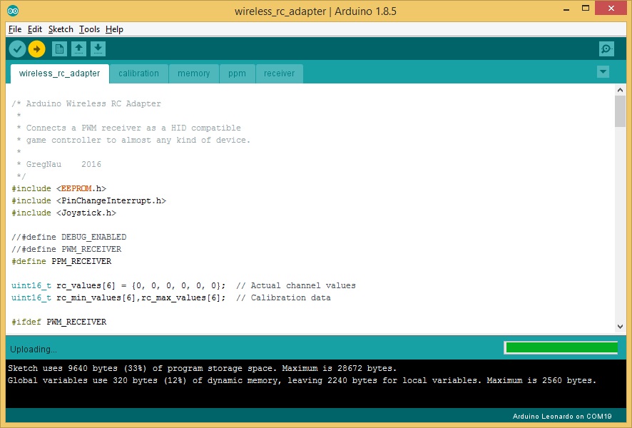
Project uploaded. Now the board is not only the Arduino but also HID (Human Interface Device).
If you Open Game controller panel (Start -> Run -> Joy.CPL), you should see the Arduino Leonardo as Game device.
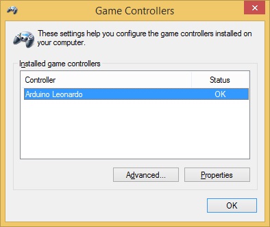
If you click the Properties, you should see the Axes and Bars moving whil moving the sticks on your TX.
Note: The first time you power on the dongle it will enter into auto calibration mode. The both leds will be lit on. You have to move all the sticks to their extents and AUX channel swiches to the on/off positions. After all the 6 channels were calibrated, the data will be stored on the Arduino EEPROM memory and dongle will start into working state.
Troubleshooting: Sometimes JOYSTICK_TYPE_MULTI_AXIS is not recognized as Joystic device. You can try changing into JOYSTICK_TYPE_JOYSTICK or JOYSTICK_TYPE_GAMEPAD in the code.
Setup in Simulators
Dongle was tested and perfectly working in DRL Simulator and Velocidrone simulator. Therefore it should work in other simulators that support USB Joystic.
In each Simulator you have to set the controller to Arduino Leonardo device. On DRL Simulator you have to select new controller.
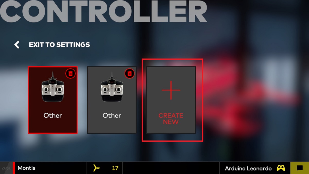
Choose Other type.
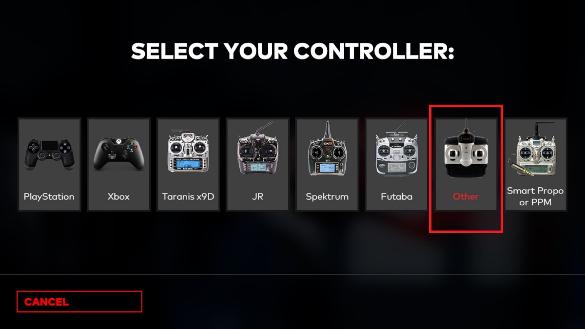
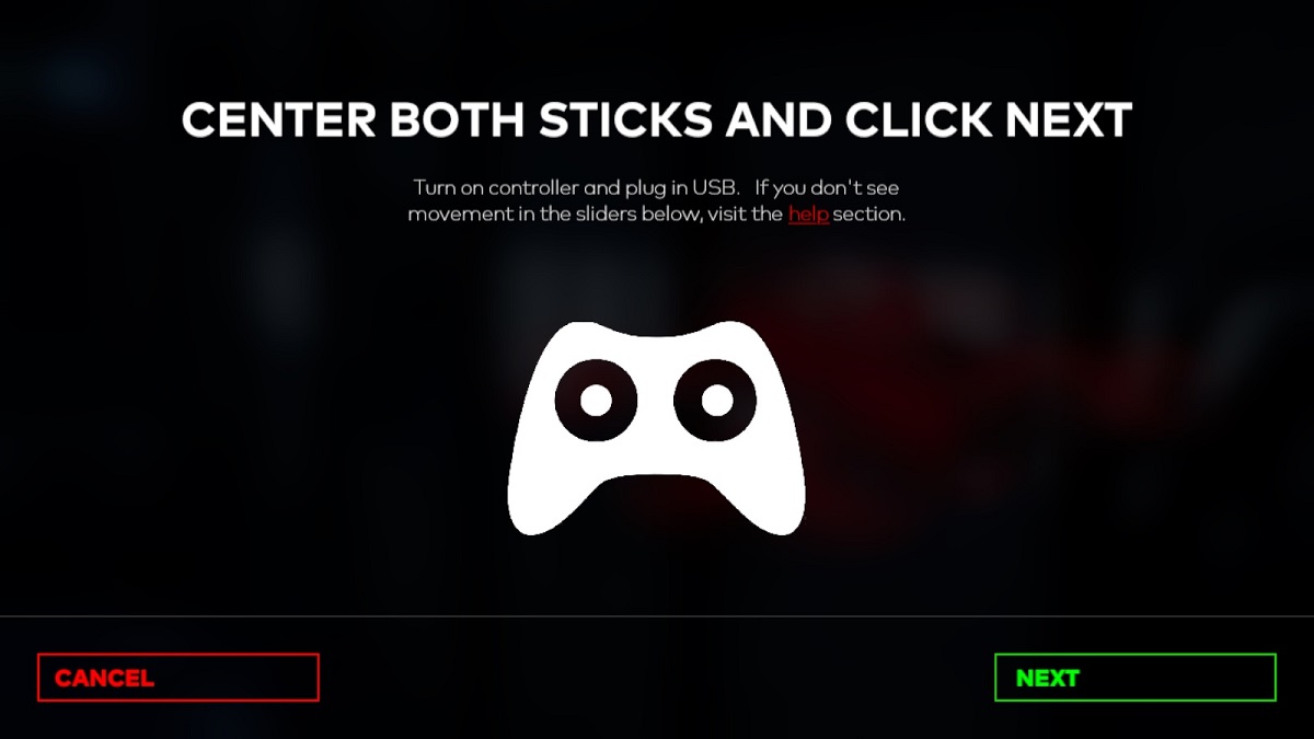
And then follow the calibration and setup wizzard. You may need to invert some of the RC channels.
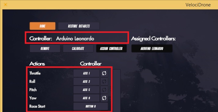
In Velocidrone Simulator you have to selecto Controller tab. Velocidrone will autodetect the Arduino Leoinardo as RC controller automatically. You may need to invert some of the channels (on my setup I had to invert Throttle and Yaw channels).
Enjoy your flight in simulators with wireless RC dongle!
]]>List of Arduino uses for RC:
1. Arduino as Eachine EV100 goggles firmware update adapter
Eachine released the first batches of EV100 goggles with a few nasty flaws. One of them was intermittent blackouts in FPV feed, which was fixed in the latest firmware releases. The problem was that EV100 needs special firmware updater tool in order to upload the firmware. Luckily Arduino can be used as firmware updating adapter. Read more here…
2. Arduino as Eachine ProDVR firmware restore tool
If your ProDVR (also HMDVR) device is bricked after firmware update process, you can easily restore it by flashing firmware directly to the serial flash ship by using the Arduino! Read more here…
3. Arduino as Caddx Turtle firmware restore tool
Updating the firmware via SD card sometimes fails and leaves the device “bricked”. No worries as there is a possibility to restore the firmware by using the Arduino. Read more here…
4. Arduino as Aomway Commander V1 Goggles DVR firmware restore tool
Firware update process can sometimes be usucessful, resulting in a bricked DVR unit on the Commander V1 goggles. Good news is that the DVR on the Commander can be fixed after a failed upgrade attempt by using the Arduino! Read more here…
5. Arduino as Lap Timer (Chorus RF Laptimer)
Want to build easy LapTimer by using only Arduino, 5.8GHz video RX module and bluetooth module? If answer is yes, then this is you weekend project! Project webpage is here…
6. Arduino as Wireless RC simulator dongle
Ever wanted to have wireless simulator dongle? Unfortunately there are no such dongle to buy anywhere. But you can easily do it by yourself! Read more here…
Other possible uses (will be updated):
- Arduino as BLHeli ESC configuration adapter
- Arduino as FTDI adapter
- Arduino as ISDT charger firmware update adapter
I’m also looking for your Arduino project suggestions in the comments section.
]]>What you will need:
- Arduino Mini Pro atmega328 board. (16Mhz 5V, about 1.30$)
It is also possible to use Arduino Nano with atmega328 16Mhz? (Possible variants on ebay:?https://goo.gl/zd0twR, Banggood:?https://goo.gl/MDmy3E)
- USB to Serial adapter. It can be FTDI, CH340G? (just look for ones that support 3.3V , about 1.30$) (Possible variants on ebay:?https://goo.gl/Ru7BXF)
- Thin wires for connecting Arduino and Serial Flash
Next parts are needed if Arduino outputs more than 3.3V on signal pins:
- Resistors for level divider 5k and 10k both (2 pcs of each value)
- Breadboard (not necessary, but very convenient)
Alternatively you can use SOP8 programming clip, so you will not have to solder the wires to the chip.
Software
- Flashrom programming utility (https://www.flashrom.org?). If your PC runs on Windows then I recommend to download already compiled windows version here:?http://ra.openbios.org/~idwer/flashrom/mingw/?(Edit: link seems to be dead now, but we have it saved on Internet Archive: https://web.archive.org/web/20181112215901/http://ra.openbios.org/~idwer/flashrom/mingw/)
- XLoader to upload binary file to Arduino board (http://russemotto.com/xloader/?)?(Edit: link seems to be dead now, here is?alternative link:?http://www.hobbytronics.co.uk/download/XLoader.zip)
- Arduino firmware (frser-duino.hex) (download link: https://drive.google.com/file/d/0BxZ43kLDo-GFOWJnQ19HYWVZVmc/view)
- ProDVR firmware file (flash.hex) (download link: https://drive.google.com/file/d/0BxZ43kLDo-GFOVN4bUJRaEoxTms/view)
Procedure step by step
First you need to flash Serprog firmware to Arduino Mini Pro:
- Connect USB – TTL converter to Arduino Mini Pro board
- If everything is ok, You should see “FTDI” or “USB-SERIAL CH340” device in device manager
- Connect Arduino Mini Pro to USB-TTL adapter (check that your FTDI or USB Serial adapter uses 3v for powering)
- Start Xloader, open [fser-duino.hex] file, set the right com port and hit “Upload”.
Now You have Flashrom compatible programmer.
Connect ProDVR serial flash IC to the Arduino. Use supplied connection schematics. For this you need to lift a bit VCC pin of the serial flash to disconnect from the rest of the board electronics and solder 5 wires: VCC, GND, CS, CLK MOSI and MISO.?Try to keep them as short as possible, about 10cm. Use small diameter wire.
Connection table:
FLASH CHIP – ARDUINO
VCC (pin 8 ) to Arduino? 3.3V output (5V would likely kill the chip, be carefull)
GND (pin 4) to Arduino GND pin
CS (pin 1) to Arduino pin 10
DO (pin 2) to Arduino pin 12
DI (pin 5) to Arduino pin 11
Clock (pin 6) to Arduino pin 13
Schematics (only if Arduino outputs 3.3V signal levels):
Once connected, try reading the contents of flash IC by running this command:
mingw32-w64-flashrom-r1781.exe --programmer serprog:dev=COM10:115200 -c MX25L1605 --read test.hex
You should get similar output to this:
E:\My\RC\Flashrom>mingw32-w64-flashrom-r1781.exe --programmer serprog:dev=COM10:115200 -c MX25L1605 --read test.hex
flashrom v0.9.7-r1781 on Windows 6.2 (x86)flashrom is free software, get the source code at http://www.flashrom.org?
Calibrating delay loop... OK.
serprog: Programmer name is "frser-duino"
Found Macronix flash chip "MX25L1605" (2048 kB, SPI) on serprog.Reading flash... done.
If everything goes OK by this far, you are ready to flash the firmware. To flash the device, start this command:
mingw32-w64-flashrom-r1781.exe --programmer serprog:dev=COM16:115200 -c MX25L1605 --write flash.hex
You should get similar output to this:
E:\My\RC\Flashrom>mingw32-w64-flashrom-r1781.exe --programmer serprog:dev=COM16:115200 -c MX25L1605 --write flash.hex
flashrom v0.9.7-r1781 on Windows 6.2 (x86)flashrom is free software, get the source code at http://www.flashrom.org?
Calibrating delay loop... OK.
serprog: Programmer name is "frser-duino"Found Macronix flash chip "MX25L1605" (2048 kB, SPI) on serprog.
Reading old flash chip contents... done.
Erasing and writing flash chip... Erase/write done.
Verifying flash... VERIFIED.
You are done! Now reconnect serial flash chip Power pin to the PCB and try to power your ProDVR.?Insert SD card and you good to go!
If you have questions or you need more details, then leave a comment below.
Created: 2018-06-19
Updated: 2020-11-15 – some links appear to be down. Alternatives provided