Specifications
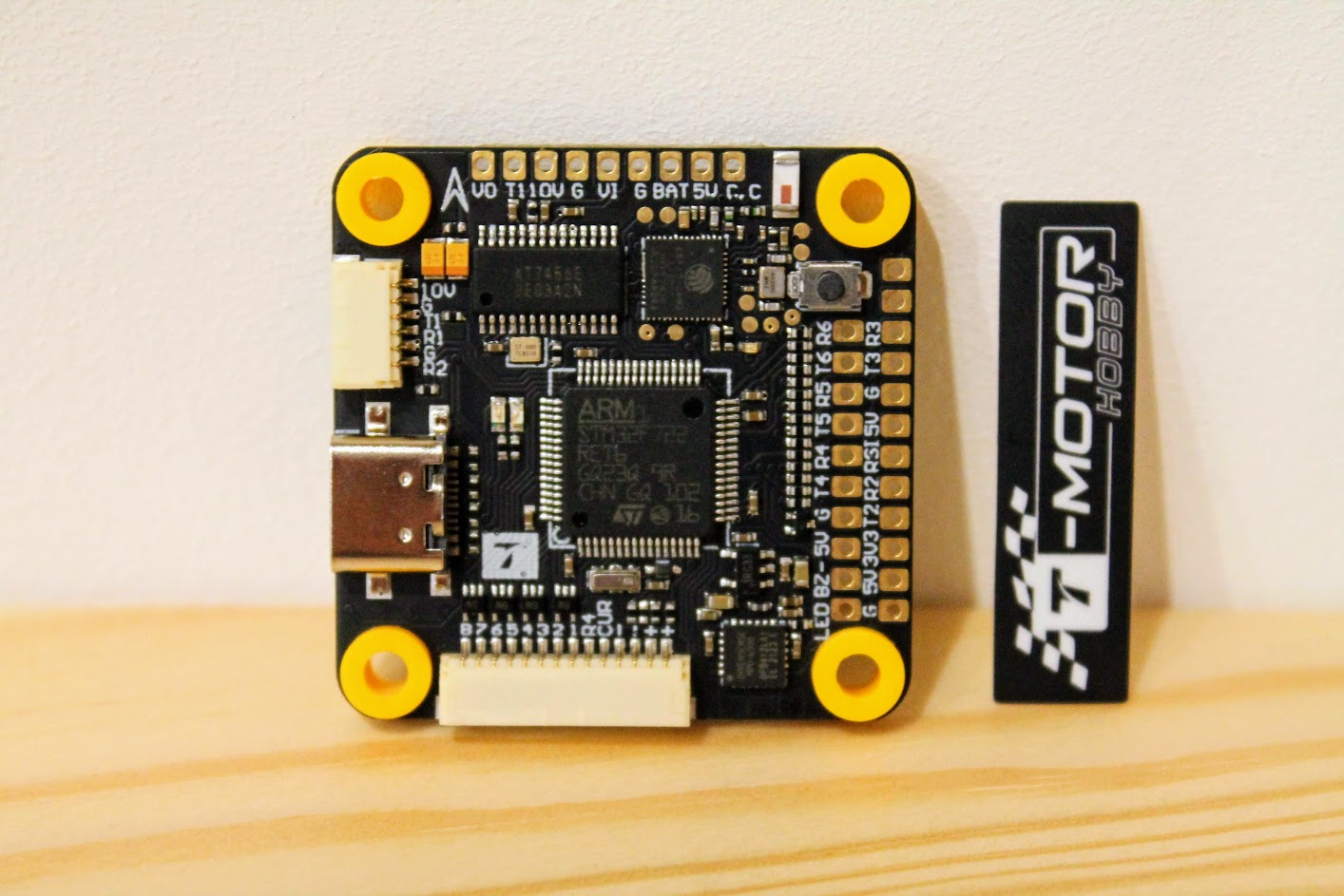
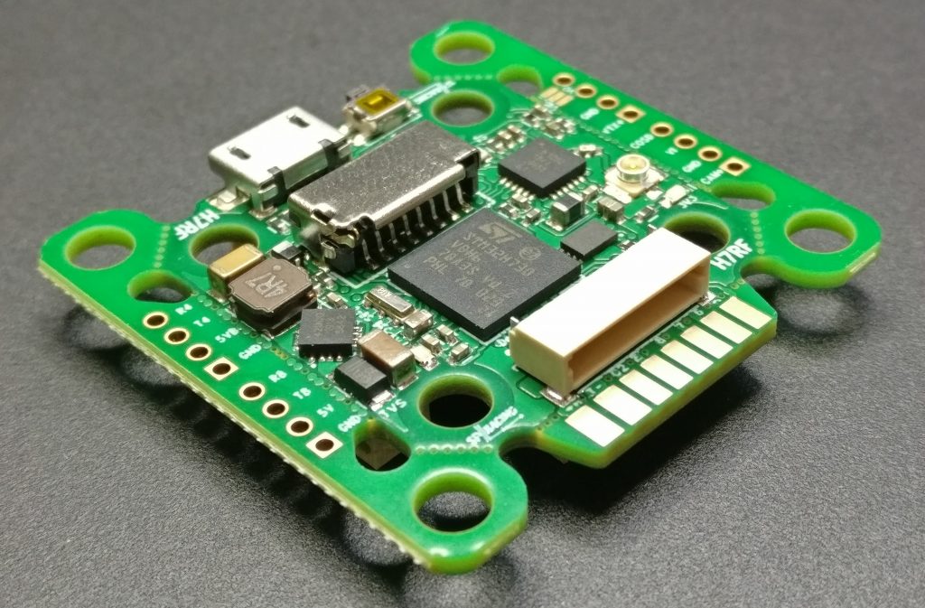
MCU: STM32F722RET6
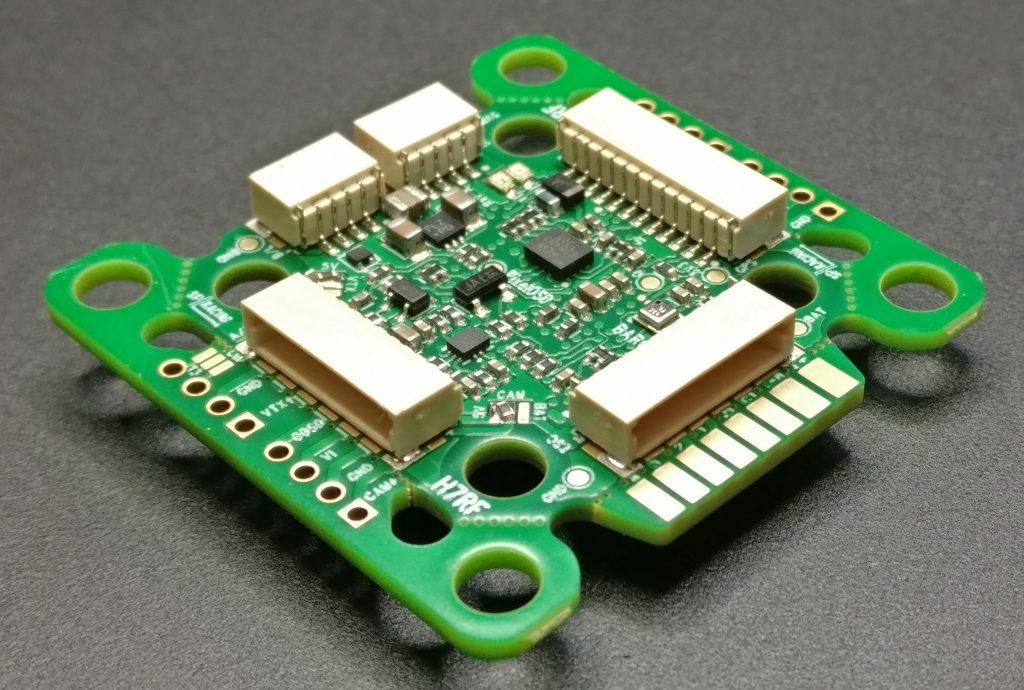
IMU: MPU6000
Barometer: BMP280
Input Voltage: 3-8S Lipo
BEC Output: 10V/2A 5V/3A
Built-in OSD(AT7456)
Built-in 16Mb Flash for data logging
ESC signal: M1 – M8
Size: 37mmX37mmX7.5mm
Installing Hole: 30.5X30.5mm/M3
USB: Type-C
Weight: 8. 1g 8.5g
Built-in SpeedyBee Bluetooth & WiFi
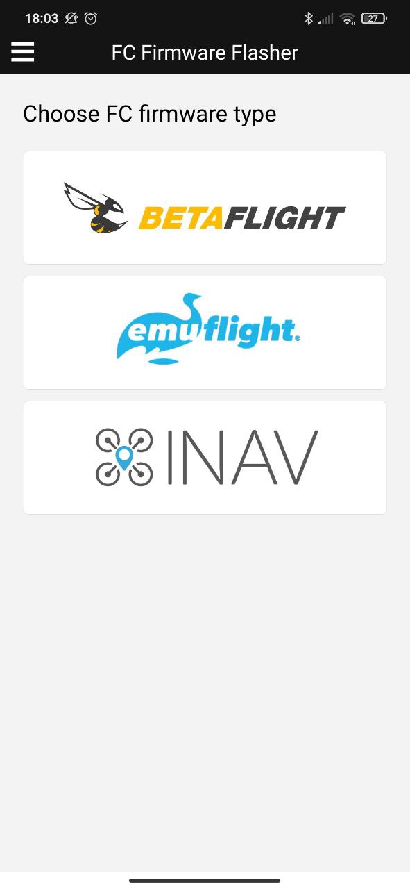
1.BetaFlight tuning wirelessly
2.Flash firmware wirelessly
3.Analyze Black-box data wirelessly
4.Set motor directions on BLHeli_ 32/S wirelessly
Target:?TMOTORF7 V2
(Beta Flight /INAV)
UARTS: 6 sets
UART1: VTX/TX
UART2: Receiver(CRSF/SBUS/iBUS/DSMX/R9MM)
UART3: GPS
UART4: ESC telemetry/RX
UART5: Vacancy
UART6: Vacancy
Closer look
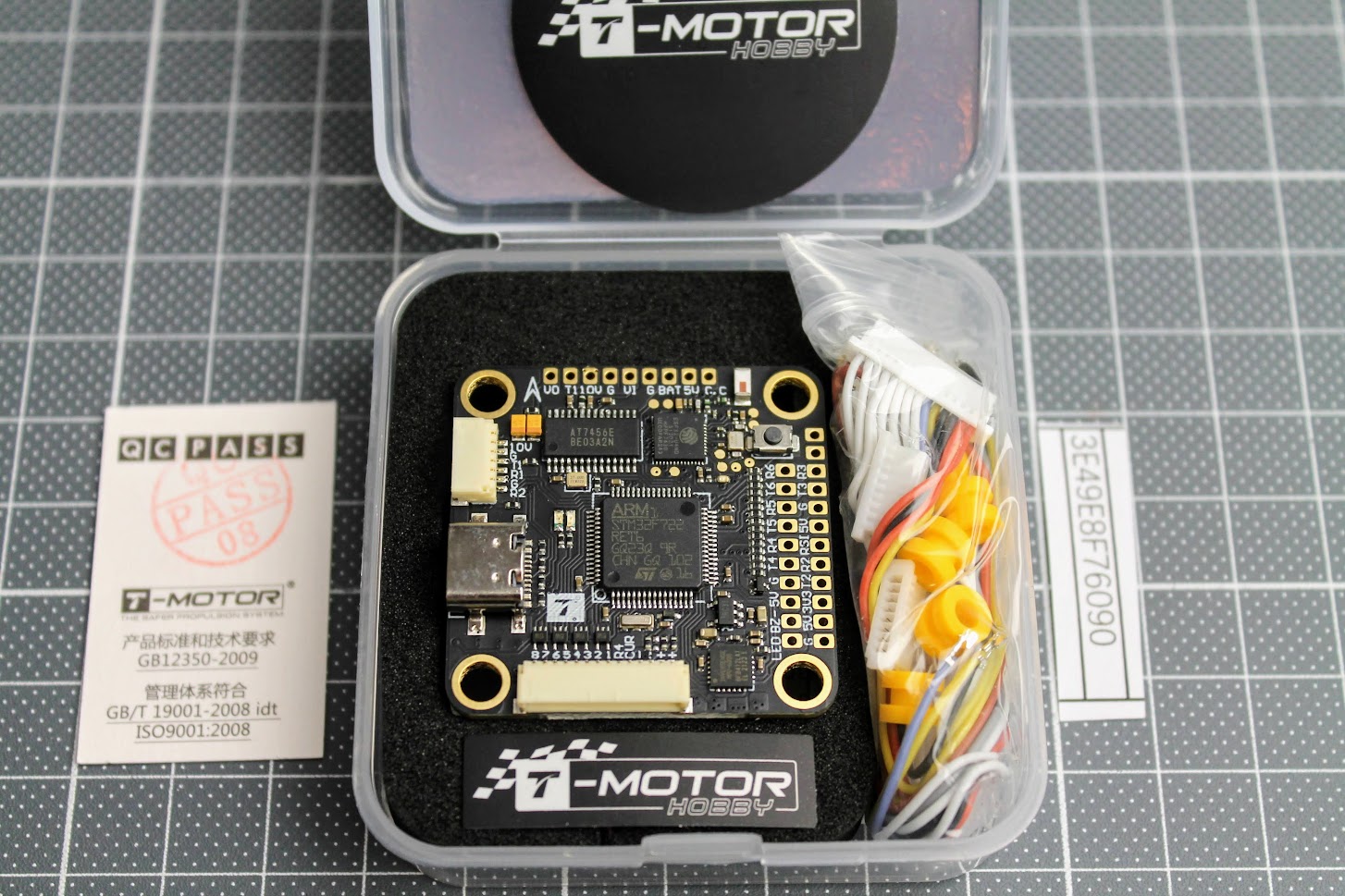
T-MOTOR F7 PRO flight controller comes with rubber grommets for vibration dampening, two sets of ESC cable with variable size SH1.0 connector, DJI Air unit compatible connector cable.??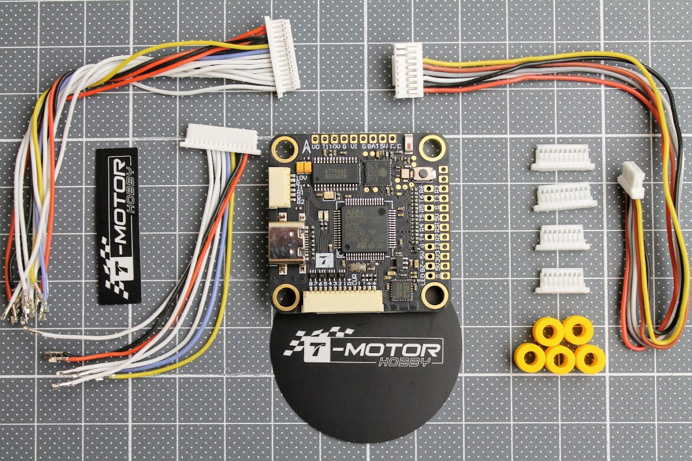
There are two ESC cables provided, one with 14 wires for setups with 6-8 motors and other, most popular, with 8 wires for up to 4 motors.

Other side of the cable can be customized to fit almost any of the ESC. You just need to push the pins inside the required size connector and in the correct order.
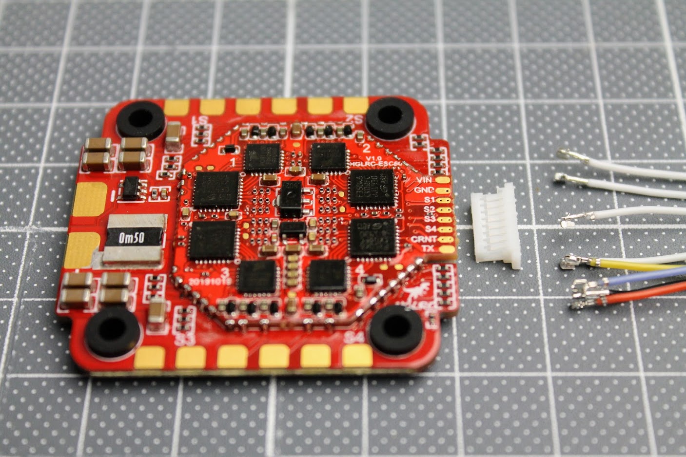
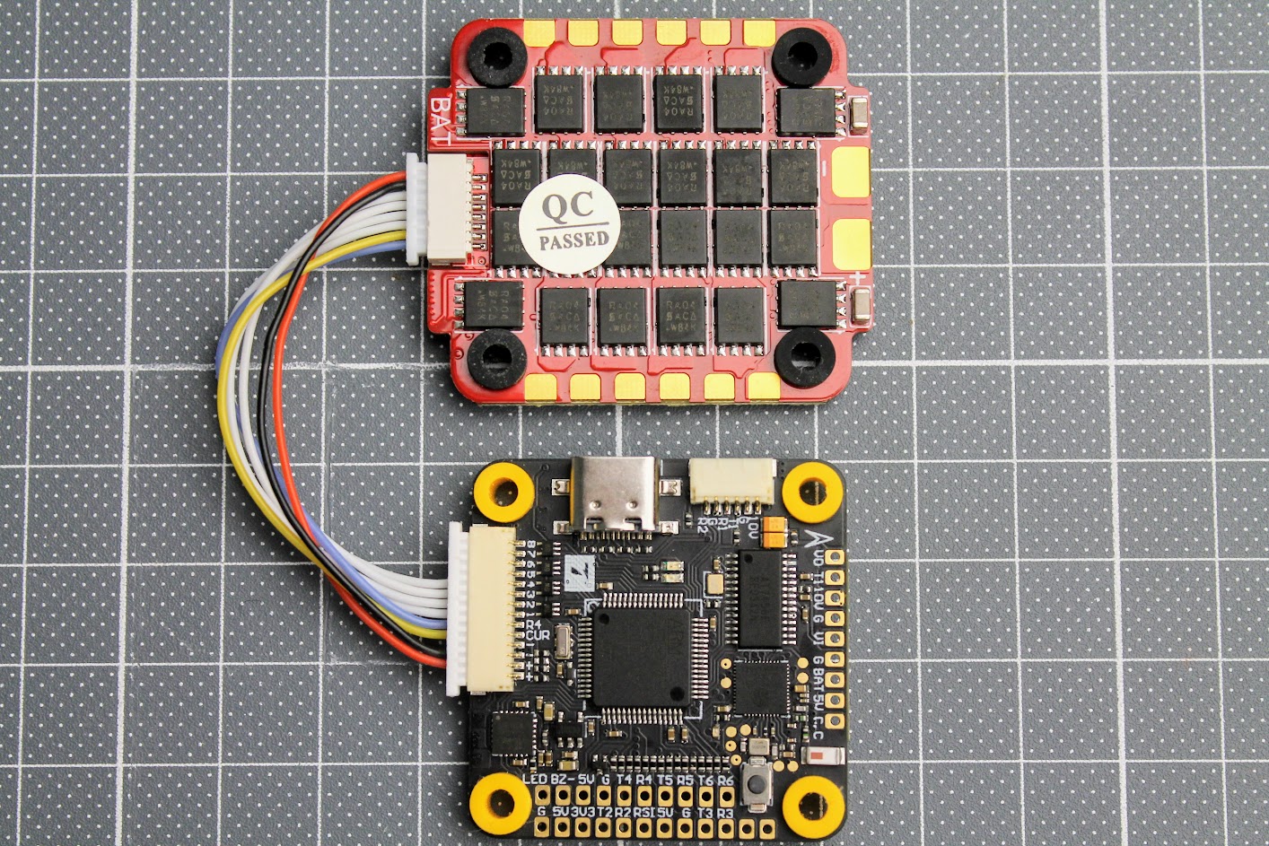
And here is the final result of customized ESC cable to HGLRC Forward 55A ESC.
On the top side of the board you can find the Espressif ESP32 chip that enables the Bluetooth and WiFi connectivity.
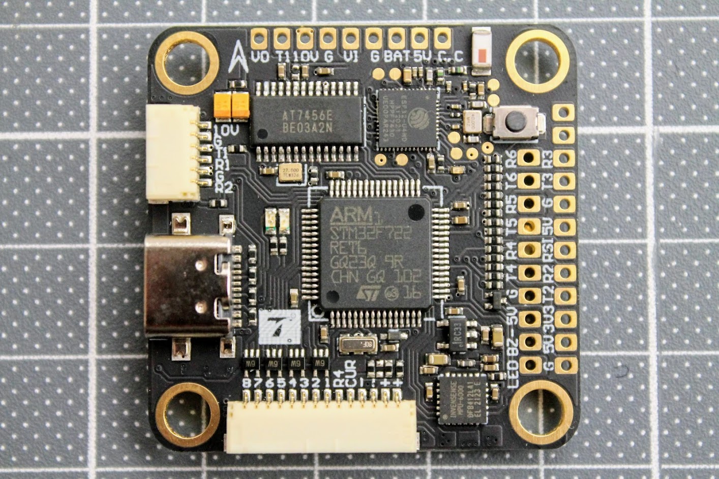
On the “front” side of the FC you can find Camera Control (C.C), 5V and?BAT, GND and Video In (VI) pads for analog FPV camera. You can select +5V or battery power source for your FPV camera. Next to them there are GND, +10V, TX1 and Video Out (VO) pads.
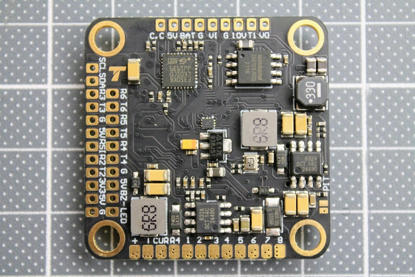
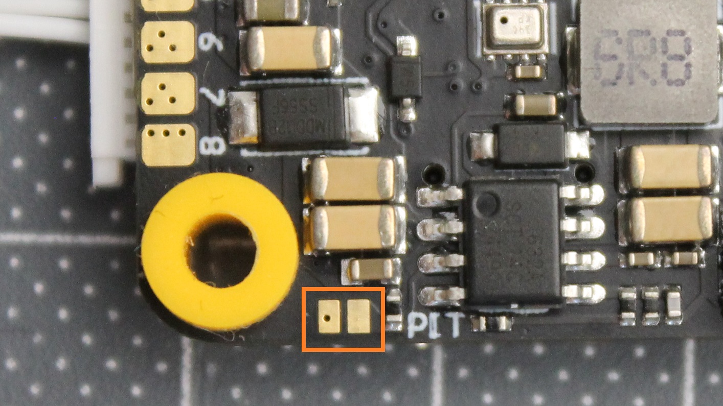
Video transmitter +10V power source can be controlled by radio transmitters switch. For this to work you need to short the two solder pads marked PIT.
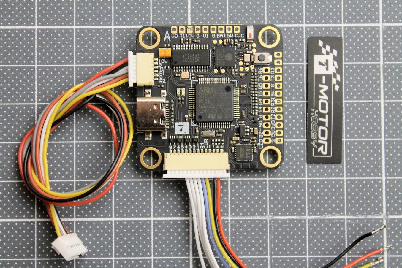
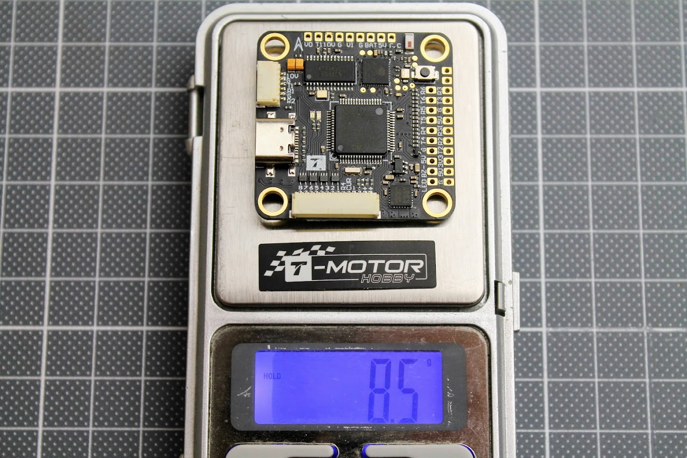
T-MOTOR F7 PRO?view with cables connected.
The weight of the F7 PRO flight controller is 8.5 grams.
Connection diagram
T-MOTOR F7 PRO flight controller connection diagram.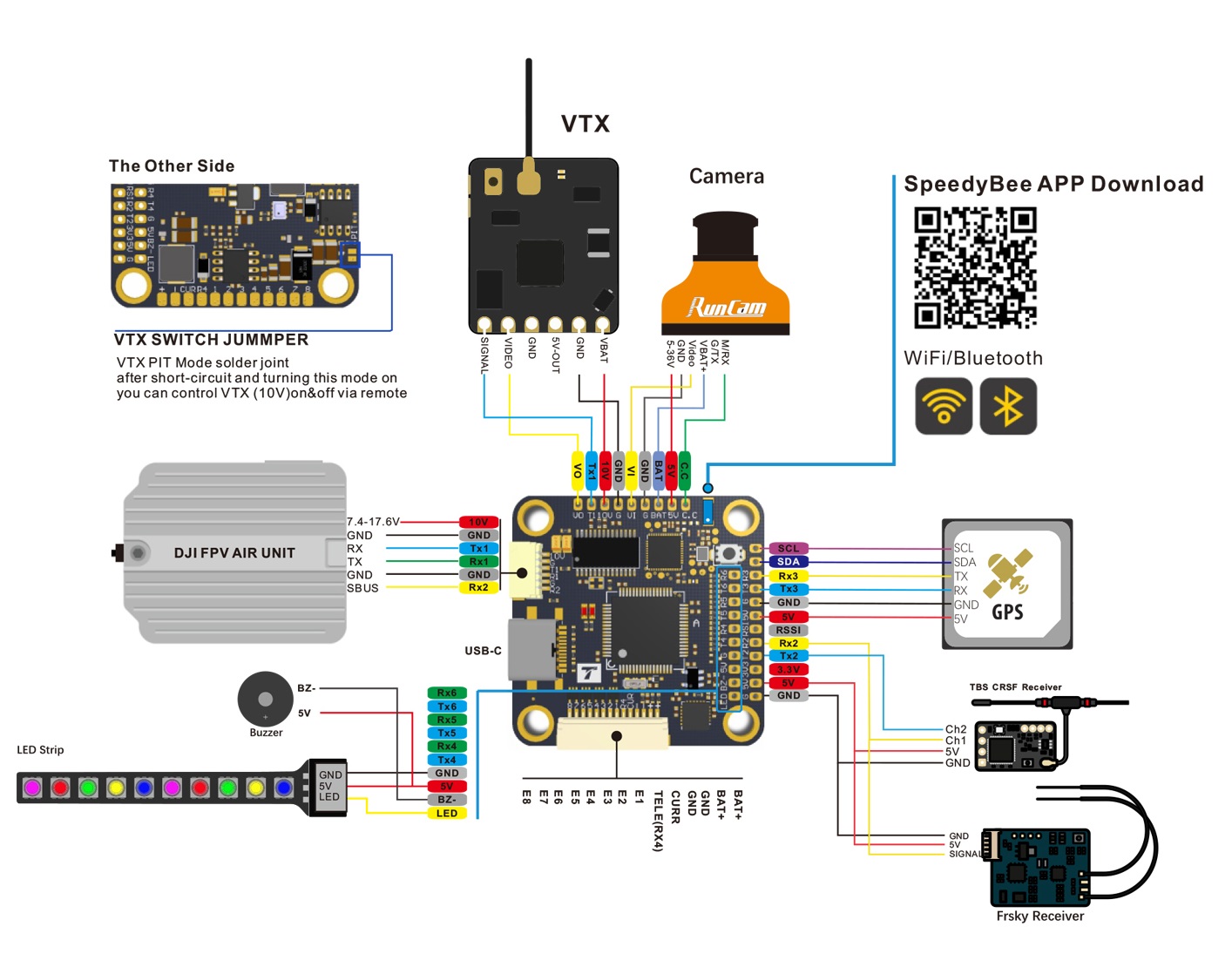
T-MOTOR F7 PRO Flight Controller default CLI dump can be found here:
https://drive.google.com/drive/folders/14sEyh1sJ2UATAgraCu9T0XeLVqJ9FHLb
Wireless configuration
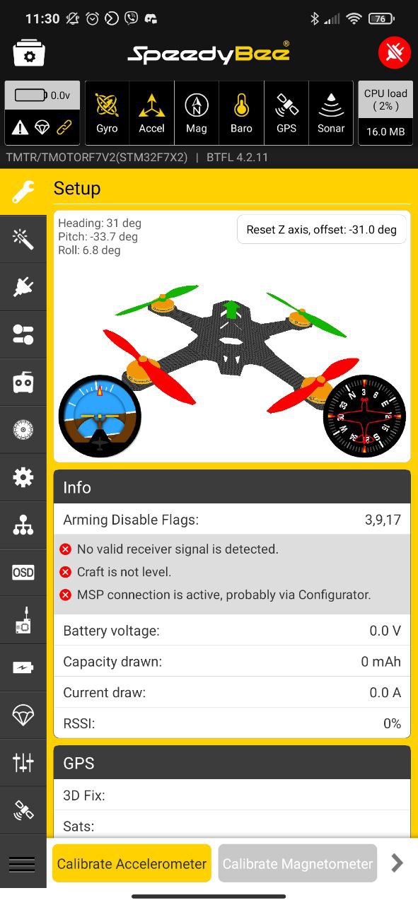
One of the most interesting features of this Flight Controller is Wireless connectivity. There is an app called SpeedyBee you can use with your phone/tablet to access almost all the Betaflight/INAV/Emuflight settings.
You can get the Android app here:?https://play.google.com/store/apps/details?id=com.runcam.android.runcambf
iOS App:?https://apps.apple.com/us/app/speedybee-app/id1150315028
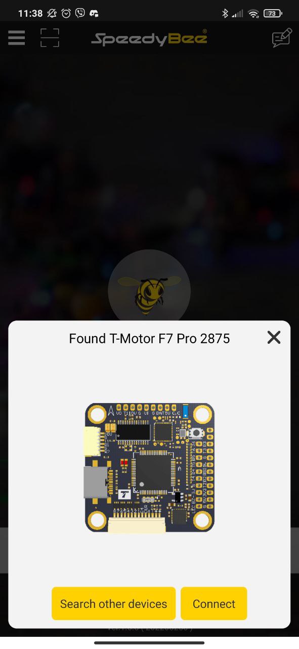
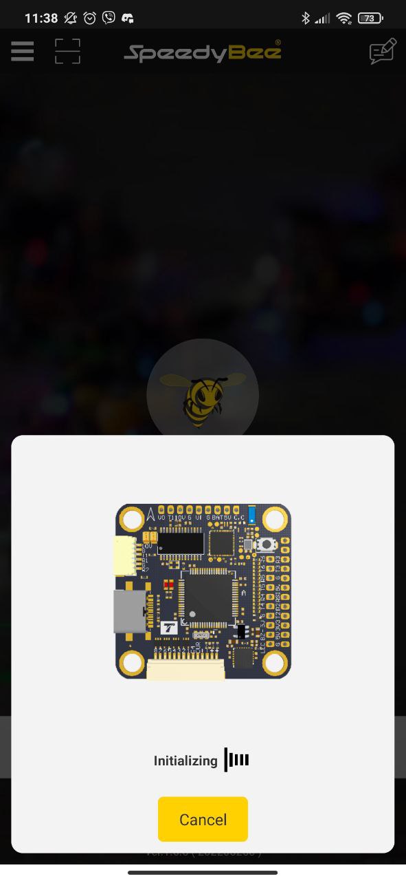
Once you have installed and run the app, select the Bluetooth option on the start screen. SpeedyBee app will find the available board, connect to it by selecting the [Connect] button.
 |
 |
 |
With SpeedyBee app you can configure or upgrade the Betaflight/INAV/Emuflight firmware, configure the BLHeli ESC settings and analyze BlackBox data.
 |
 |
 |
Some notes
SpeedyBee app sometimes refused to connect to the F7 PRO FC after it was left connected for a longer time on the bench. Looks like the board gets too hot with active Bluetooth or WiFi connectivity. You have to keep the FC board cooled actively if you want to maintain the stable connectivity. My observations say that F7 PRO FC heats up the most with WiFi connectivity on.
T-MOTOR F7 PRO can be purchased from
Disclaimer: This item was supplied by Banggood for a fair and unbiased review. Banggood never asked for a positive review and never influenced my opinion in any way. I’m trying my best to stay uninfluenced and give only my own opinion. All affiliate links if there are any help me purchase items for future reviews and tests.
]]>HDZero SmartAudio feature is useful for a race events to be able to change channel quickly without looking at the OSD and to have pit mode setting. On the other side – it consumes additional TX pad on the FC? for SmartAudio function to work.
Notes:
– HDZero VTX outputs 0.1mW when SmartAudio PIT mode is ON.
– HDZero? VTX does not support SmartAudio out range PIT mode.
– When HDZero VTX boots up, it will automatically detect the existence of a valid SmartAudio?link with FC within 10 seconds. If the link exists, FC will fully control race VTX’s RF output power and?working frequency.
VTX table needs to be set as shown below. Please note that HDZero?VTX supports all 8 channels (R1 ~ R8)?on R band, and 2 channels (F2 and F4) on F band.
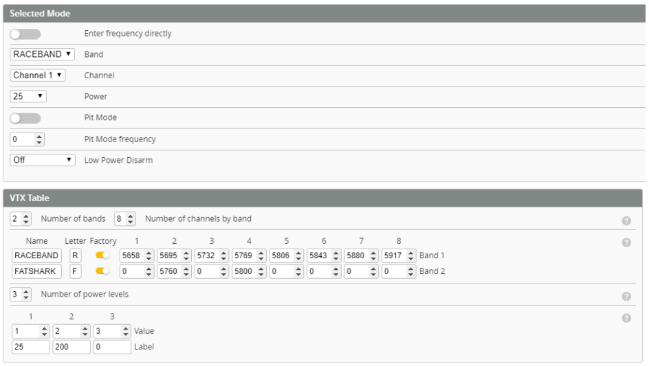
The above setting can also be done with the following CLI commands:
vtxtable bands 2
vtxtable channels 8
vtxtable band 1 RACEBAND R FACTORY 5658 5695 5732 5769 5806 5843 5880 5917
vtxtable band 2 FATSHARK F FACTORY 0 5760 0 5800 0 0 0 0
vtxtable powerlevels 3
vtxtable powervalues 1 2 3
vtxtable powerlabels 25 200 0
save
HDZero VTX tables can be downloaded from here:?https://drive.google.com/file/d/1djG56KZ-XbCW3x4Pyu64Wf66aHNZmLLT/
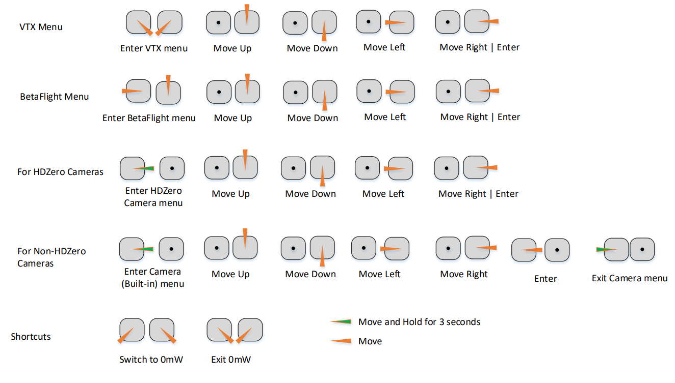
SmartAudio VTX settings can be controlled from Betaflight menu with stick commands or Betaflight Lua script.
Stick commands for VTX, Betaflight and Camera Menu
]]>
BLHeli_32?Rev32.9 changelog
- Added support for RPM controlled variable motor pwm frequency
- Added support for very high demag compensation
- Added support for adaptive low rpm power protection
- Modified relaxed stall protection mode to have no startup boost
- Greatly reduced noise level in the Dshot real time erpm data
- Improved rampup consistency, that helps make e.g. flip stops more precise
- Fixed a bug that caused MM32SPIN160 MCUs to occasionally hang
- Some smaller fixes
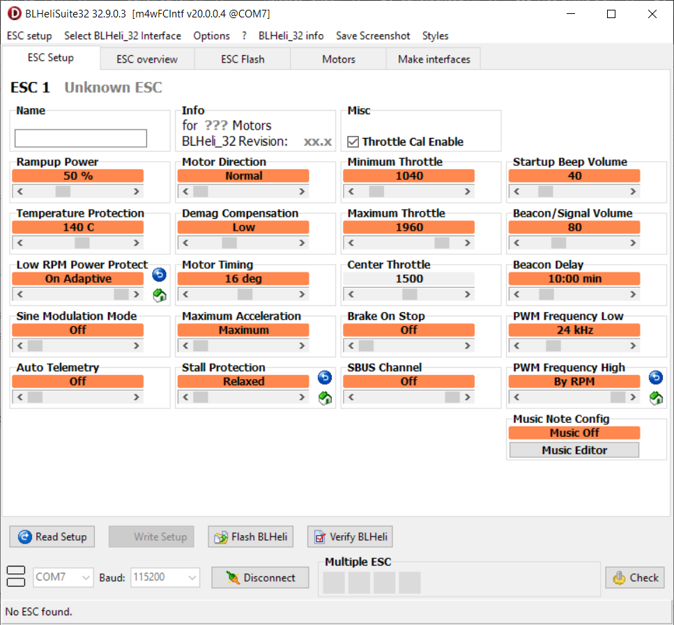
BLHeli_32?Rev32.9 changes in detail
PWM frequency:
Code revisions from Rev32.9 and on support variable pwm frequency where the pwm
frequency is controlled by motor RPM. This mode is called “By RPM”.
This mode can be invoked by setting pwm high frequency to maximum.
By letting pwm frequency be controlled by RPM instead of throttle, some artifacts that can
arise from throttle control can be alleviated.
Demag Compensation:
Code revisions from Rev32.9 and on also support a setting called “Very High”, for which
power is cut even more aggressively.
Generally, a higher value of the compensation parameter gives better protection.
If demag compensation is set too high, maximum power can be somewhat reduced for some
motors.
Low RPM Power Protect:
Code revisions from Rev32.9 and on have a mode called “On Adaptive”. This setting is
intended for large low kV motors running on a fairly low battery voltage. But it can be used,
and is indeed suitable for any motor kV and battery voltage. In this mode, the code calculates
the kV*voltage and adjusts the low rpm power protection accordingly
Stall protection:
Code revisions from Rev32.9 and on have a tweak to the relaxed stall protection mode, where
there is no boost on startup for this mode. So if you are flying with really low throttle and the
motors stop e.g. due to reverse flow, then they will just gently start up again on the low
throttle.
You can download the BLHeli_32?suite from here:?https://github.com/bitdump/BLHeli/releases
Warning! Updating the firmware of almost any device can lead to the device being bricked or broken. You should carefully think before updating and taking the risks.??
]]>BLHeli_S, the most common ESC firmware, runs on the cheap 8bit MCU and has reached the edge of the hardware capabilities. The next ESC evolution was the development of the BLHeli32 firmware that runs on the 32bit based MCUs. The one major downside of this firmware – it is proprietary and is licensed for manufacturers.?Peter Smith (aka AlkaMotors) created the open source firmware for the BLHeli_32 compatible ESC’s called AM32 (AM stands for the AlkaMotors).
Features of the AM32 firmware
- Firmware upgradable via Betaflight passthrough – only support G4, F4 and F7 FCs, and make sure your Betaflight firmware is up to date when you try to use passthrough
- Servo PWM, DShot300, DShot600, DShot1200 and ProShot motor protocol support
- Bi-directional DShot
- KISS standard ESC telemetry
- Variable PWM frequency
- Sinusoidal startup mode, which is designed to get larger motors up to speed
- Ghost branch restart and stuck rotor protection
- Open Source firmware
The major problem with the AM32 firmware is the… absence the off shelf ESC’s with the preloaded AM32 firmware.? This can might be changed with the release of the?Skystars KM55A – the first in the market 4in1 ESC with AM32 preinstalled.
Flashing the AM32 firmware to the BLHeli32 ESC
AM32 firmware is compatible with the most 32bit BHLeli32 ESCs,? but the problem is the BLHeli32 ESCs are usually locked and cannot be updated with the AM32 firmware in the easy way. In order to write the AM32 to the BLHeli32 ESC you need to unlock the MCU and this means you need to erase all the MCU contents and this process is irreversible, so you cannot flash the BLHeli32 firmware back. Once you have erased the BLHeli32 firmware, you need to flash the bootloader with the STLink tool. After the bootloader is flashed you can use Betaflight passthrough to upload the AM32 firmware. You can use the online tool ESC-Configurator (https://esc-configurator.com/) or you can use the standalone ESC configuration tool, available for?downloaded for?WINDOWS, and?LINUX.
The AM32 firmware can be downloaded from here:?https://github.com/AlkaMotors/AM32-MultiRotor-ESC-firmware/releases
The list of the AM32 compatible ESCs is here:?https://github.com/AlkaMotors/AM32-MultiRotor-ESC-firmware/wiki/List-of-Supported-Hardware
Interview with the creator of AM32 firmware:
]]>All flight controllers, that run Betaflight, Emufligh,?Cleanflight?or other flight software, are based on the STM32 type microcontroller or MCU?(also can be called as “processor“).?STM32?is a family of 32-bit?microcontroller?integrated circuits?by?STMicroelectronics.?The STM32 family consists of series of?microcontrollers: H7, F7, F4, G4,?F3, F2, F1, F0,...?Internally, each microcontroller consists of the processor core,?static RAM,?flash?memory, debugging interface, and various peripherals. It is the main processing device of the flight controller. It runs the dedicated program called firmware (e.g. Betaflight) and controls the quad by sensing an measuring the environment by the help of external sensing devices – gyroscopes, accelerometers, compasses, barometers and GPS.
The main differences between the STM32 microcontroller series are: internal architecture, clock speed, internal flash size, number of interfaces for peripherals and other.
| Code | Core | Max freq [MHz] | Max FLASH [KB] | Max SRAM [KB] | Target |
|---|---|---|---|---|---|
| H7 | CortexM7 | 400 | 2048 | 1024 | High performance |
| F7 | CortexM7 | 216 | 2048 | 512 | High performance |
| F4 | CortexM4 | 180 | 2048 | 384 | High performance |
| G4 | CortexM4 | 170 | 512 | 128 | High performance |
| F2 | CortexM3 | 120 | 1024 | 128 | High performance |
| L4 | CortexM4 | 80 | 1024 | 320 | Low power |
| F1 | CortexM3 | 72 | 1024 | 96 | Mainstream |
| F3 | CortexM4 | 72 | 512 | 80 | Mainstream |
| F0 | CortexM0 | 48 | 256 | 32 | Mainstream |
F1
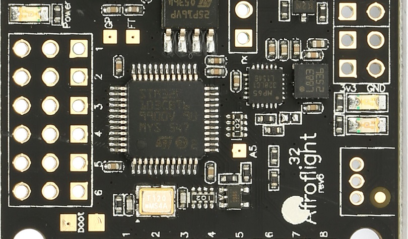
F1 series of the MCU were released in 2007.?This is the MCU that started the flight controllers era. NAZE32?was the first flight controller, based on STMF103 and Baseflight firmware. The most commonly used MCU was?STM32F103CBT6 with 128Kb of the flash space for firmware. This MCU currently is outdated as?Betaflight support for F1 MCU was discontinued in 2017. The last version that supports F1 is Betaflight 3.2 .
F3
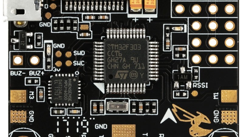
F3 series of the MCU were released in 2012. They have up to 72MHz core speed and up to 256 Kb general flash size.?The F3 is almost pin-to-pin compatible with the STM32 F1-series. Higher clock speed allows to run 2x higher loop times than earlier generation of F1 microcontrollers, up to 8KHz. F3 microcontrollers have 3 serial ports for peripherals.
This MCU currently is outdated as?Betaflight support for F3?MCU was discontinued in 2017. The last version that supports F3 is Betaflight 4.0. Read about this?here.
F4
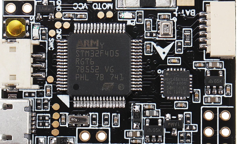
F4?series of the MCU were released in 2011. So the F4 MCU in fact was released before the?F3. They have marginally faster clock speeds, that enable to run up to 32KHz loop times.?Most popular F4 MCU are?STM32F405RGT6 with 168Mhz and?STM32F411CCU6 with 100MHz clock speed, but with reduced footprint size for smaller boards.
G4
STM32 G4 series MCU is released first in 2019. G4 is featured with extensive analog signal processing and rich advanced analog peripherals, has up to 512Kb of flash and up to 128Kb RAM memory, runs on up to 170MHz speeds. G4 provides better power efficiency and performance compared to the older F3/F4 series. G4 has 5 hardware UARTS.
First flight controller with STM32G4 MCU is FETtec KISS G4 flight controller, released in 2021-10.
[Picture pending]
F7
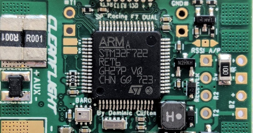
F7 series of the MCU were released in 2014. They have up to 216MHz?core speed and up to 2048Kb general flash size. The F7 is?pin-to-pin compatible?with the STM32 F4-series. The most popular MCU is?STM32F722RET6 has 512Kb?of flash memory, 128Kb or RAM and 5 hardware UARTS.
H7
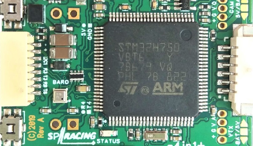
H7 is the newest MCU, released in 2017. It was designed as faster and more cost effective alternative to F7 series. Clock speed was almost doubled up to 400MHz. thanks to improved semiconductor manufacturing process from 90nm down to 40nm. This also reduces power consumption. H7 series are cheaper than F7 series, due to reduced internal flash size (using cheap external memory instead).
Inverted/uninverted serial ports
F3, F7 and H7?series microcontrollers have built-in ability to invert the serial signal. Other MCU’s – F1 and F4 have no build-in inverters, so either you need to invert SBUS and S.Port signals by external inverters or the flight controller manufacturer has to implement the additional inverting components on the FC board.
[To be continued]
2019-04-05 Article created
2021-10-05 G4 MCU introduced.
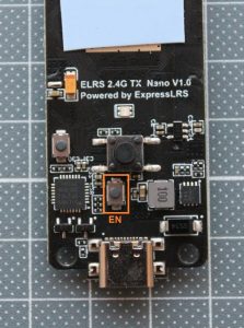
Lets take a look at the BetaFPV 2.4GHz ExpressLRS?Nano TX and RX modules.
Specifications
BetaFPV Nano TX transmitter
 |
 |
Available @ BetaFPV:?https://betafpv.com/collections/expresslrs-series/products/elrs-nano-tx-module
Banggood:?https://www.banggood.com/search/betafpv-expresslrs.html
Packet refresh rate: 25Hz/50Hz/100Hz/200Hz (915MHz/868MHz)
25Hz/50Hz/150Hz/250Hz/500Hz (2.4GHz)
RF output power: 100mW/250mW/500mW
Frequency bands (Nano RF Module 2.4G version): 2.4GHz ISM
Frequency bands (Nano RF Module 915MHz/868MHz version): 915MHz FCC/868MHz EU
Input voltage: 5V~12V
USB port: Type-C
BetaFPV Nano receiver
 |
 |
Available @ BetaFPV: https://betafpv.com/collections/expresslrs-series/products/elrs-nano-receiver
Banggood:?https://www.banggood.com/search/betafpv-expresslrs.html
Weight: 0.7g (receiver only, w/o antenna)
Size: 12mm*19mm
Telemetry power: 20dBm
Frequency bands (Nano receiver 2.4G version): 2.4GHz ISM
Frequency bands (Nano receiver 915MHz/868MHz version): 915MHz FCC/868MHz EU
Input voltage: 5V
Antenna connector: IPEX MHF
Closer look
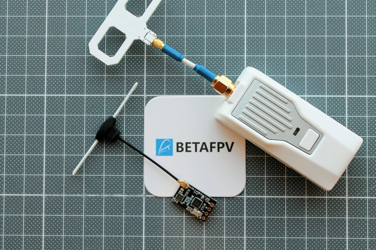
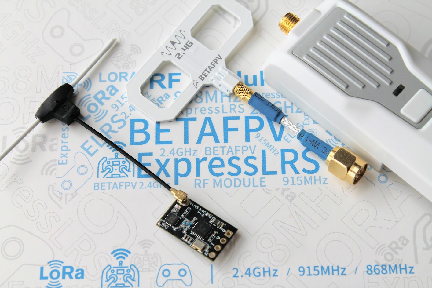
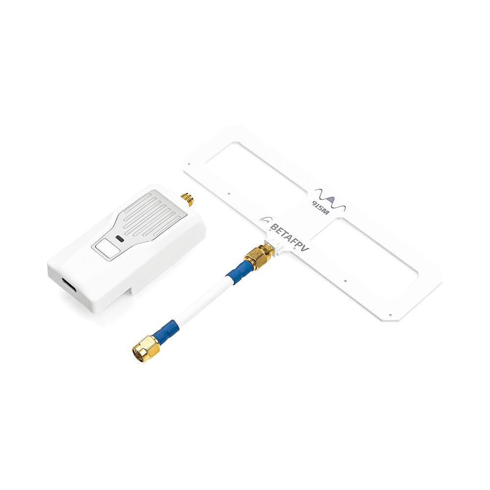
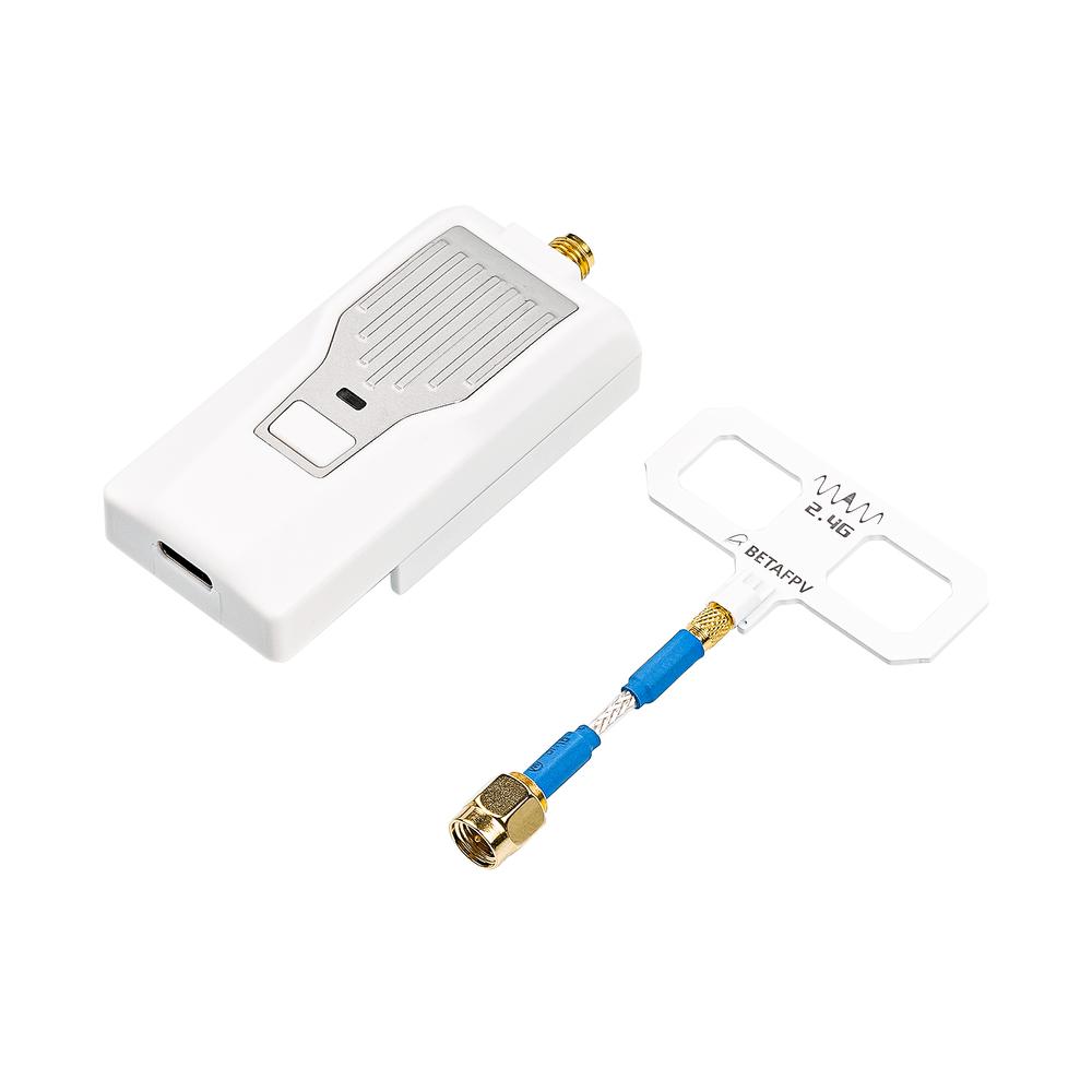
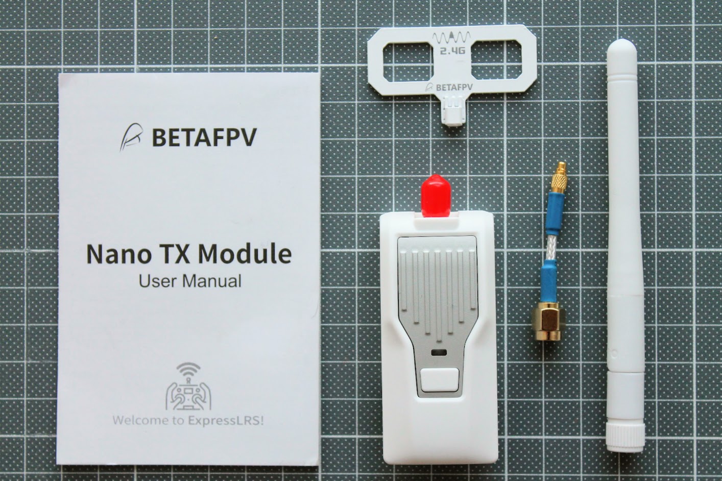
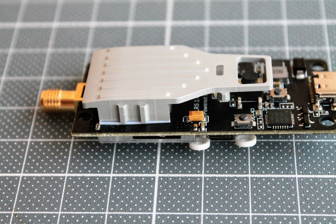
BetaFPV ExpressLRS Nano TX module comes with two antennas – linear whip style dipole antenna and Moxon type antenna
Disassembled BetaFPV Nano TX module.
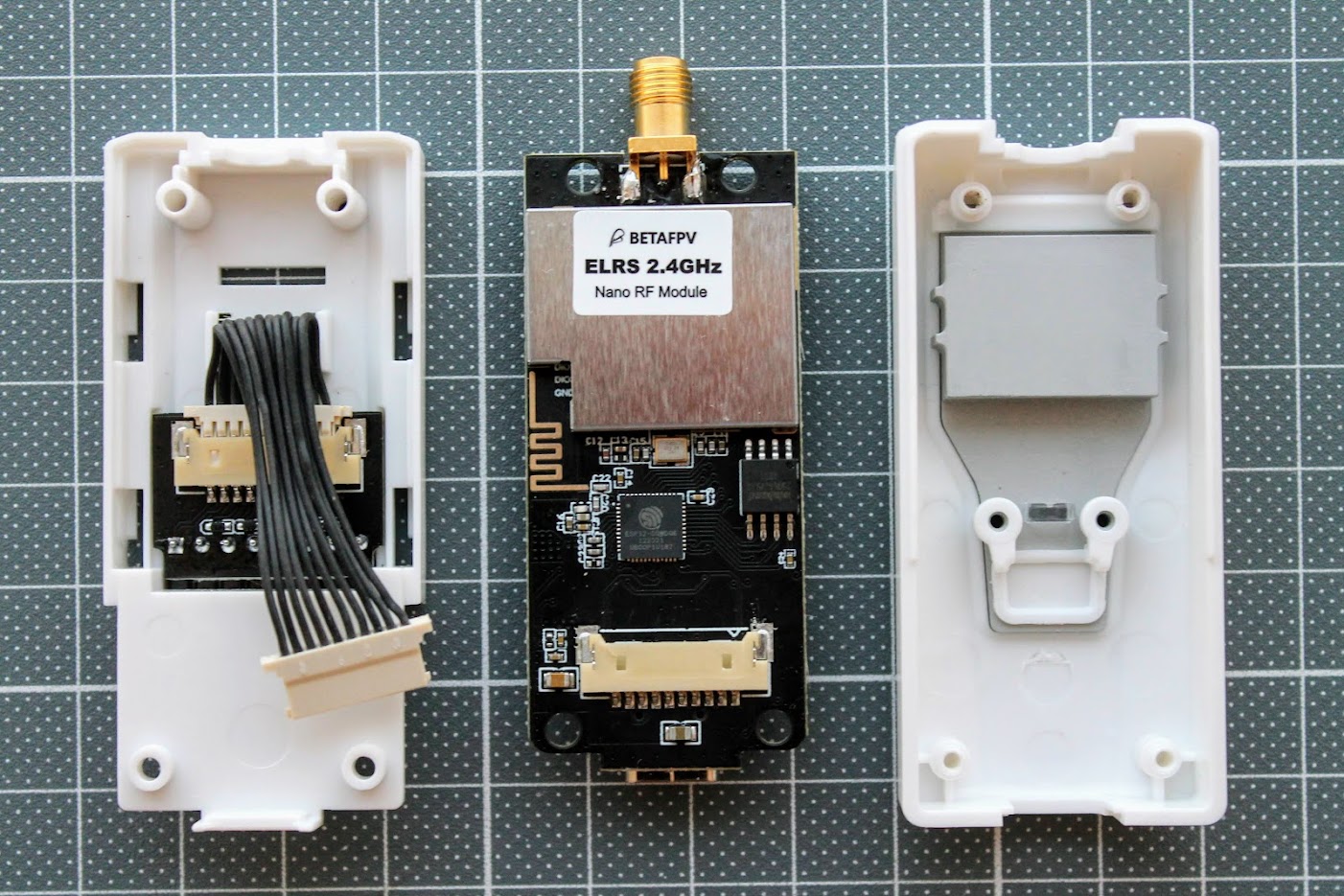
BetaFPV Nano TX module has thick metal heatsink for cooling the RF chip. It is exposed to the outside and can get pretty hot on higher power output levels. This heatsink does the job well and the module does not overheat even on the 500mW output.
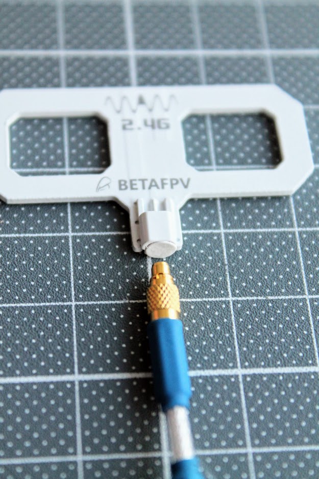
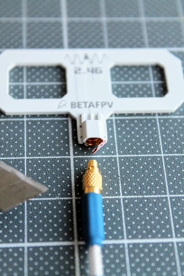
The supplied Moxon type antenna has a cover on the MMCX connector. You should remove it before plugging the MMCX pigtail.
 |
 |
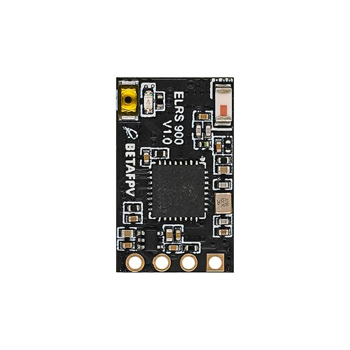
BetaFPV ExpressLRS Nano receiver comes with T-style dipole antenna, silicone wires, two heat shrinks and a pin header if you need to solder one.
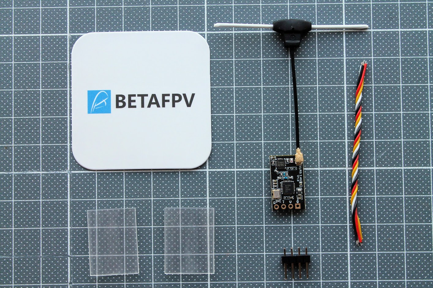
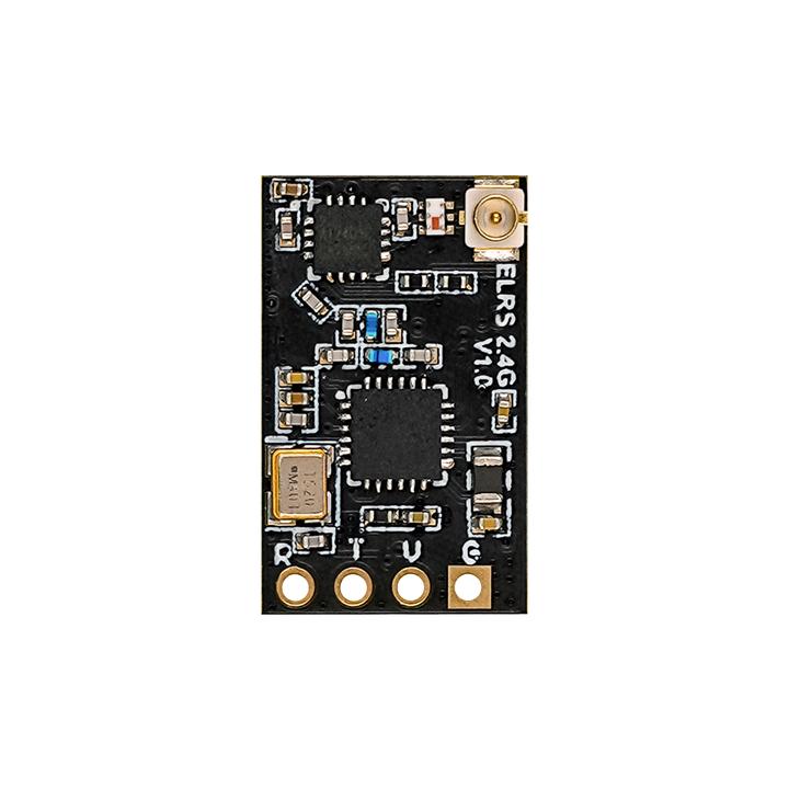
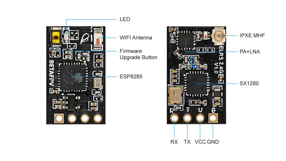
You can see the standard pinout pattern R T V G (RX, TX, +V, GND) on the antenna side. This is the same pinout as on TBS Crossfire Nano receiver, and is recommended design pattern for all ExpressLRS receivers.
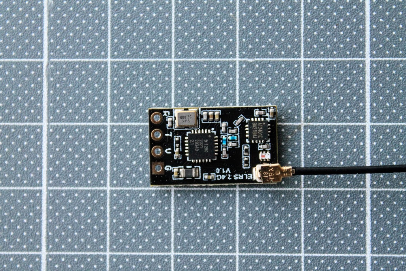
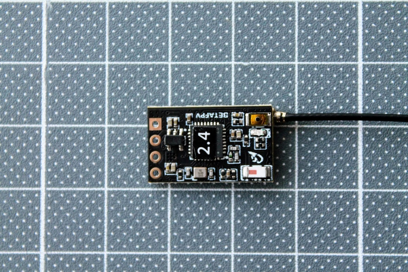
There is a ceramic antenna for WIFI connectivity, the boot button and the LED on the other side of the receiver.
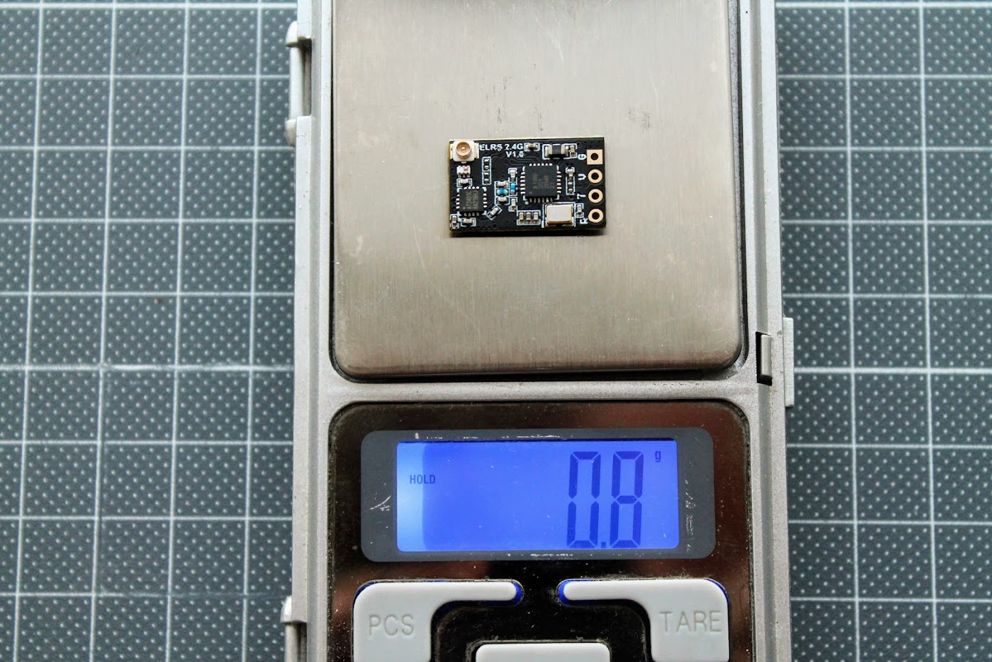
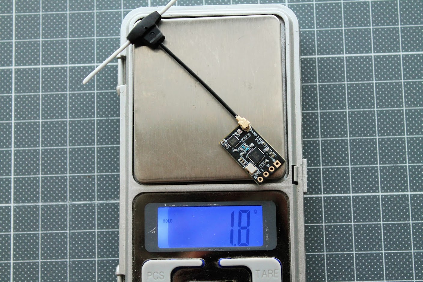
The weight of the bare BetaFPV Nano receiver is only 0.8 grams.
The weight of the supplied T-style antenna is 1 gram.
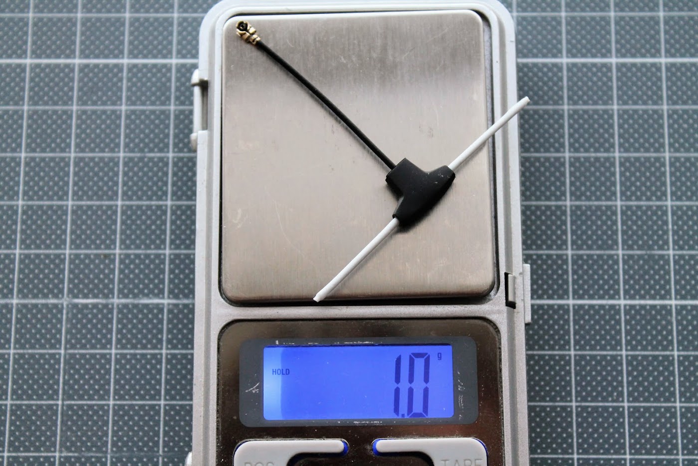
And the total weight of receiver and antenna is 1.8 grams.
BetaFPV Nano receiver is the first and (so far) the only receiver with power amplifier (PA+LNA). It has 100mW telemetry output and in theory better sensitivity (longer range).
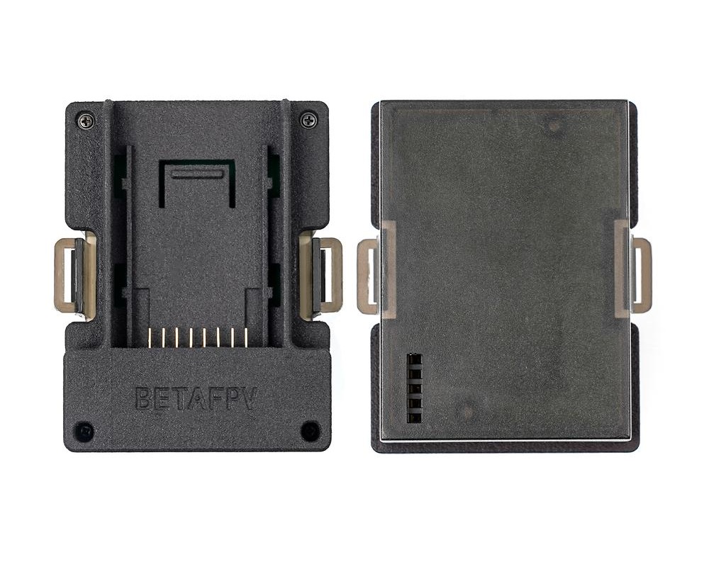
BetaFPV also sells the JR Lite to JR?type (or so called Nano to Micro) adapter box.
BetaFPV adapter:? https://betafpv.com/collections/rx-tx/products/micro-nano-module-adapter
BetaFPV TX module firmware upgrade
There are two options how to upgrade the TX module firmware – via WIFI or via UART(USB). For WIFI method you will need the OpenTX radio with ExpressLRS Lua script running. For UART method you can connect the TX module directly to the PC and you don’t need the Radio for flashing the ExpressLRS firmware to TX module.
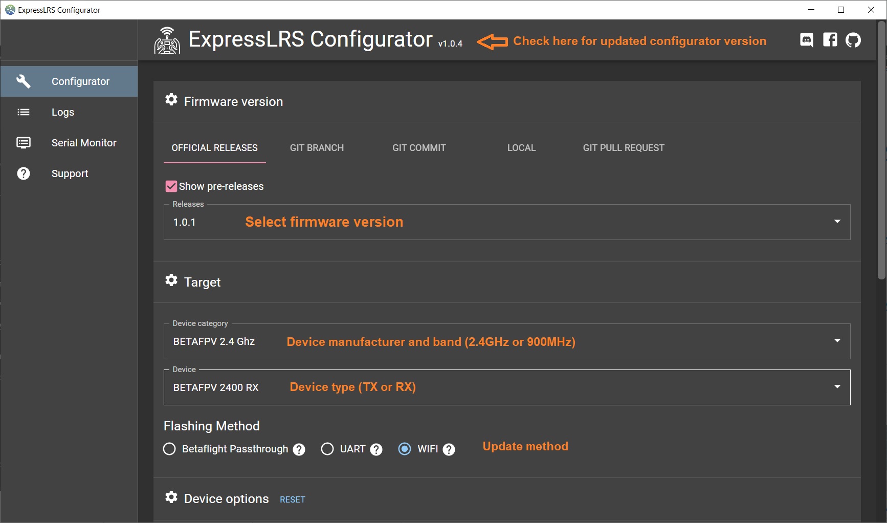
Compiling the firmware
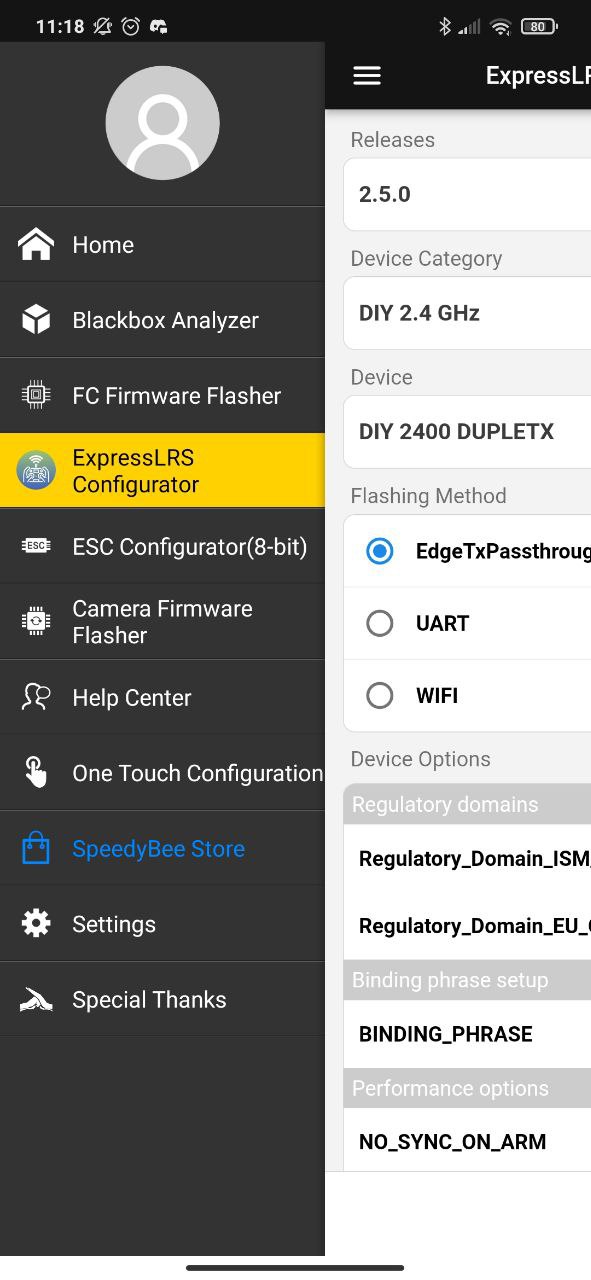
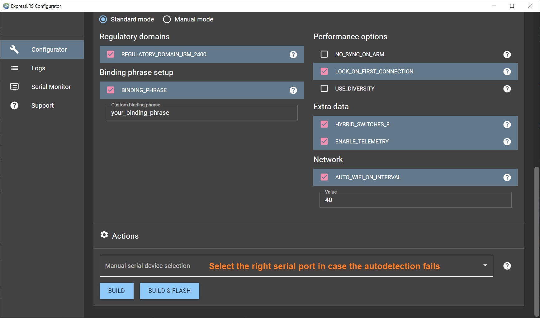
First you need to compile the firmware with the ExpressLRS Configurator. Select the firmware version, device type and flashing method.
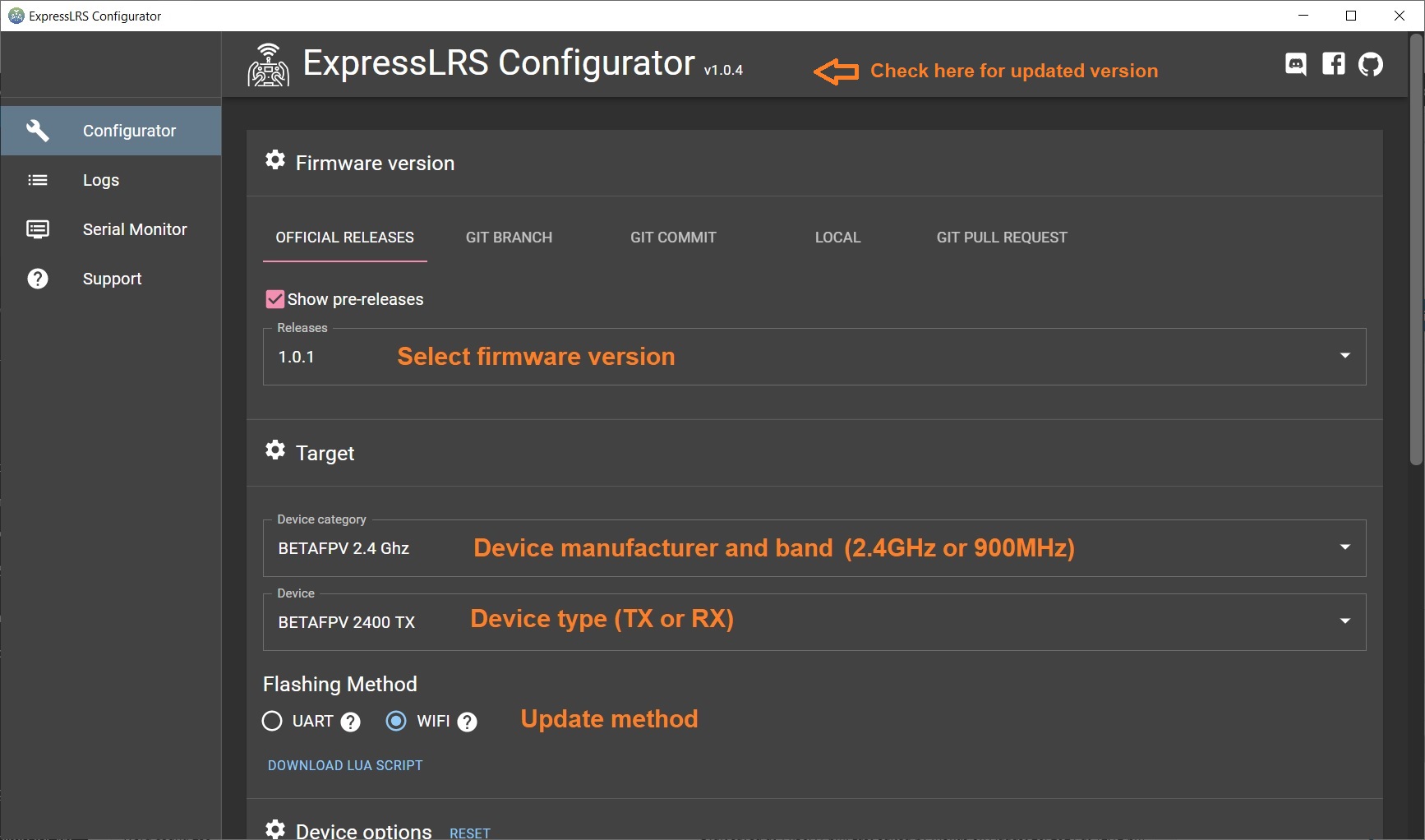
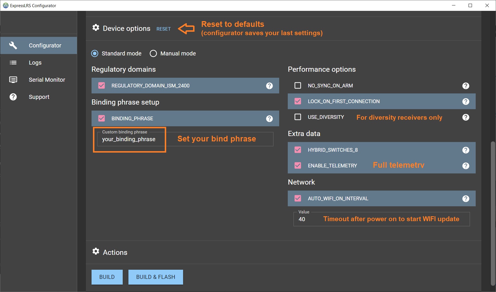
Set the device options.
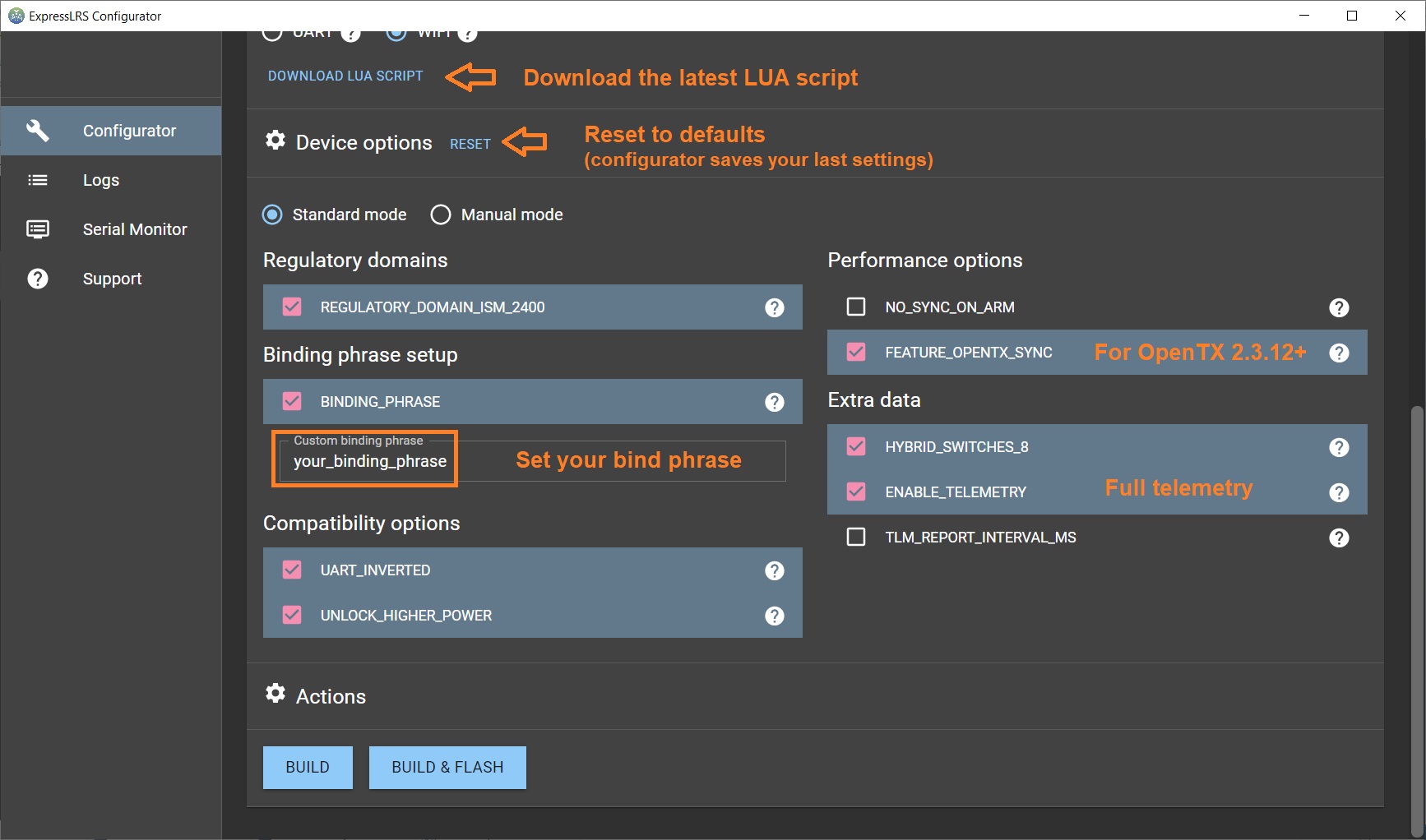
And press the [Build] button. The compiling result should be thefirmware.bin file that can be uploaded via WIFI or UART.
Via WIFI
Select?WIFI Update?from the ELRS Lua script. The TX module will enter into the WIFI mode. Then you have to connect your PC to the WIFI Hotspot the TX module created. It will show up in your network as?ExpressLRS TX Module, and the password is expresslrs. Then open the browser and go to a specific IP Address http://10.0.0.1/. In the web page, select the the compiled firmware file?firmware.bin? by pressing the [Choose file] button. Hit the [Update] button
Read more about the updating the ExpressLRS firmware here:?ExpressLRS?– Complete Guide
Via UART?(USB)
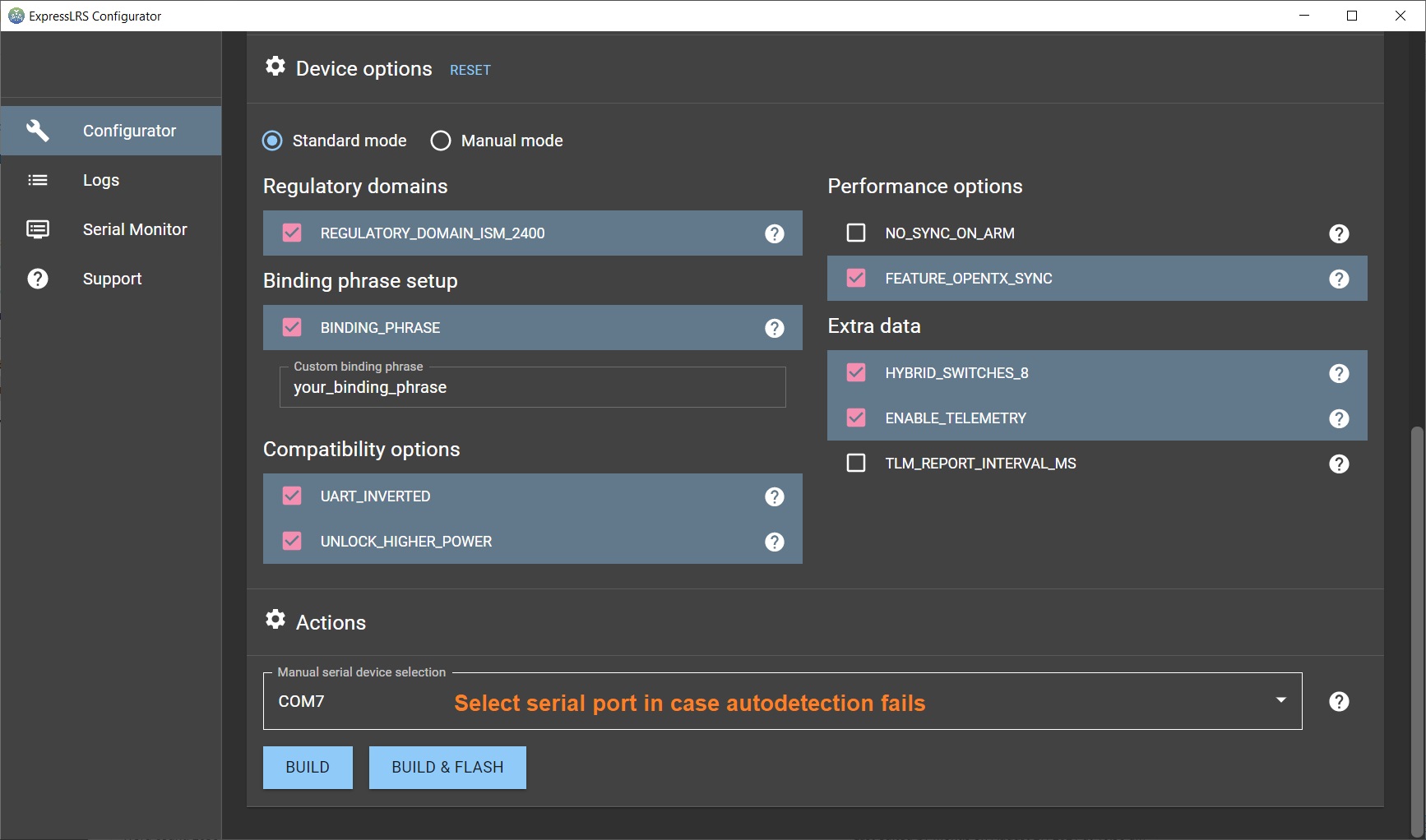
For flashing via the UART, you need to connect the TX module to the PC via USB-C cable.
Select [Build & Flash] button when compiling the firmware in the ExpressLRS Configurator. The configurator will compile and try to upload to the detected serial port. If ExpressLRS configurator somehow fails to detect the serial port, then you should set the port manually.
Read more about the updating the ExpressLRS firmware here:?ExpressLRS?– Complete Guide
BetaFPV TX update via UART problem
The first batch of the BetaFPV ExpressLRS TX modules have hardware issue, which prevents the module to automatically go into UART firmware update mode.?BetaFPV forgot to add a capacitor on the EN pin of the ESP32, so it doesn’t reset properly. You might get the “Failed to connect to ESP32: Tined out waiting for packet header” error.
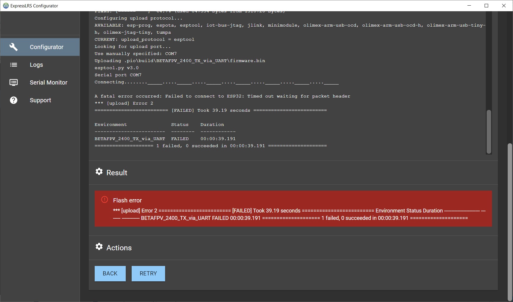
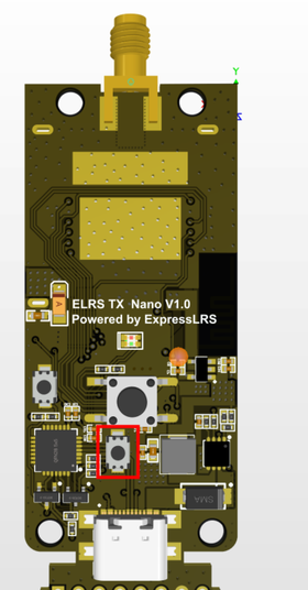
If you have this issue, the you can still use flashing by WIFI option or you can open the TX module and press the EN button while uploading the firmware via UART (USB), pictured below.
 |
 |
This can be fixed by adding small SMD capacitor to the circuit.
Nice job done fixing the BetaFPV ExpressLRS TX module by QUADMOVR.
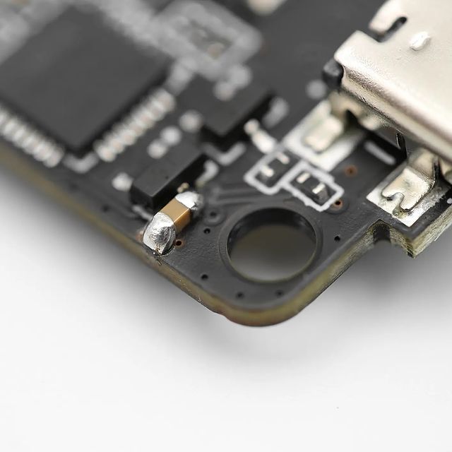
UART update fix by QUADMOVR
BetaFPV Receiver firmware upgrade
There are three ways how to upgrade the receiver firmware – via WIFI, via Betaflight Passthrough or via UART. For UART mode you need to connect the USB to TTL dongle to the ExpressLRS receiver. So you should use WIFI or Betaflight Passthrough, for the first one you only need to power the ExpressLRS receiver ad for the second one you need it to connect to the Flight controller, running Betaflight firmware.
Compiling the firmware
First you need to compile the firmware with the ExpressLRS Configurator. Select the firmware version, device type and flashing method.
Set the device options.
And press the [Build] button. The compiling result should be thefirmware.bin file that can be uploaded via WIFI or
Via WIFI
Power on the receiver, but keep your radio turned off. Receiver will enter into the WIFI mode after the AUTO_WIFI_ON_INTERVAL?timeout and the led on the receiver should start blinking fast. Then you have to connect your PC to the WIFI Hotspot the RX module created. It will show up in your network as?ExpressLRS RX Module, and the password is expresslrs. Then open the browser and go to a specific IP Address http://10.0.0.1/. In the web page, select the the compiled firmware file?firmware.bin? by pressing the [Choose file] button. Hit the [Update] button
Read more about the updating the ExpressLRS firmware here:?ExpressLRS?– Complete Guide
Via Betaflight Passthrough
Connect the Flight Controller to the PC via USB cable. Select?[Build & Flash] button when compiling the firmware in the ExpressLRS Configurator. The configurator will compile and try to upload to the detected serial port. If ExpressLRS configurator somehow fails to detect the serial port, then you should set the port manually.
OpenTX configuration
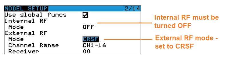
Open?“MODEL SETUP” in the OpenTX radio, turn OFF the “Internal RF“, enable “External RF” and select “CRSF” as the protocol.
Download and install ExpressLRS LUA script (ELRS.lua file) in to the OpenTX radio.
Read more about the ExpressLRS LUA script here:?ExpressLRS?– Open Source Long Range radio control system- Complete Guide
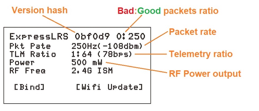
Run the ELRS Lua script. You should see the similar options setup window:
ExpressLRS Binding
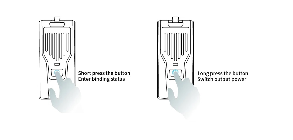
BetaFPV Nano TX module could enter into binding mode via ELRS.Lua script.?Alternatively you can short press button on the module to enter the binding mode. Note, that TX module LED does not indicate the binding mode. TX module will automatically stop biding after 5 seconds, so you need to set the binding mode in receiver first.
Power output
You can change the power output level by using ERLS.lua script or by long pressing the power/bind button on the TX module. Power output level cycles between 100-250-500mW and the led color changes accordingly.
The RF TX module output power and LED indication as shown below.
| LED Color | RF output power |
| Blue | 100mW |
| Purple | 250mW |
| Red | 500mW |
Links
BetaFPV ExpressLRS?TX on BetaFPV:?https://betafpv.com/collections/expresslrs-series/products/elrs-nano-tx-module
BetaFPV ExpressLRS?RX on BetaFPV:?https://betafpv.com/collections/expresslrs-series/products/elrs-nano-receiver
BetaFPV ExpressLRS on Banggood:?https://www.banggood.com/search/betafpv-expresslrs.html
BetaFPV Nano TX user manual:?https://support.betafpv.com/hc/en-us/article_attachments/4403878641433/Manual_for_Nano_RF_TX_Module.pdf
BetaFPV Nano receiver user manual:?https://support.betafpv.com/hc/en-us/article_attachments/4403870819737/Manual_for_Nano_Receiver.pdf
ExpressLRS guide:?ExpressLRS –? Open Source Long Range radio control system – Complete Guide
Disclaimer: This item was supplied by BetaFPV for a fair and unbiased review. BetaFPV never asked for a positive review and never influenced my opinion in any way. I’m trying my best to stay uninfluenced and give only my own, honest and as much as possible unbiased opinion. All affiliate links, if there are any, help me purchase items for future reviews and tests.
]]>
Specifications
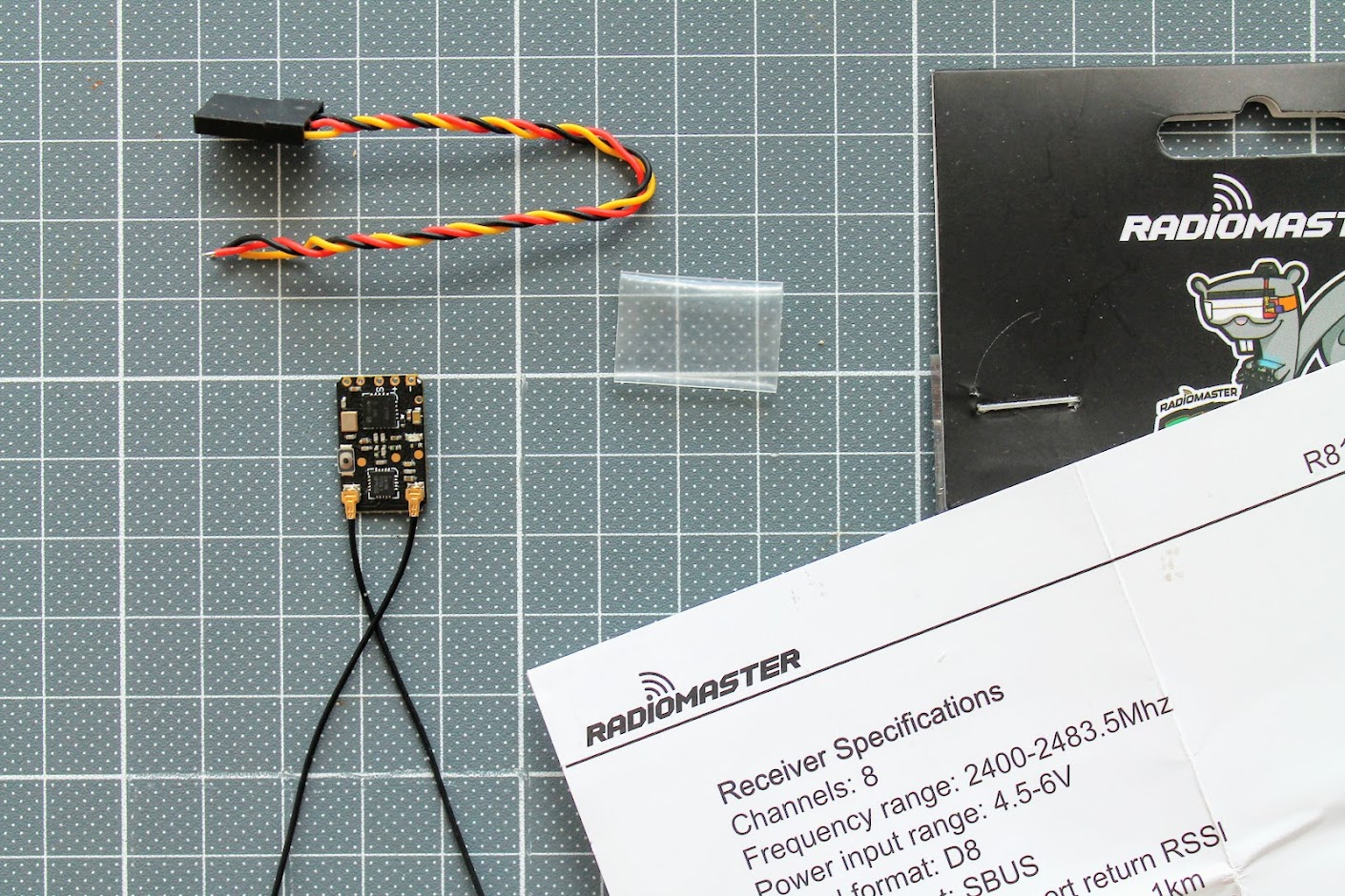
Radiomater R81 – D8 Nano SBUS Receiver
Channels: 8 (+1 for RSSI)
Frequency range: 2400-2483.5Mhz
Power input range: 4.5-6V
Signal format: Frsky D8 Compatible
Output format: SBUS
RSSI: RSSI on Ch9 of Sbus Output
Range: > 1km
Antenna length: Approximately 6cm
Size: 17x11mm
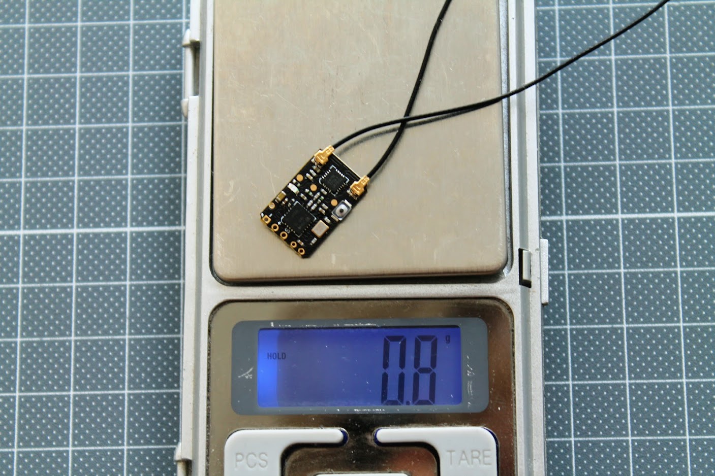
Weight: 2 grams (actually less)
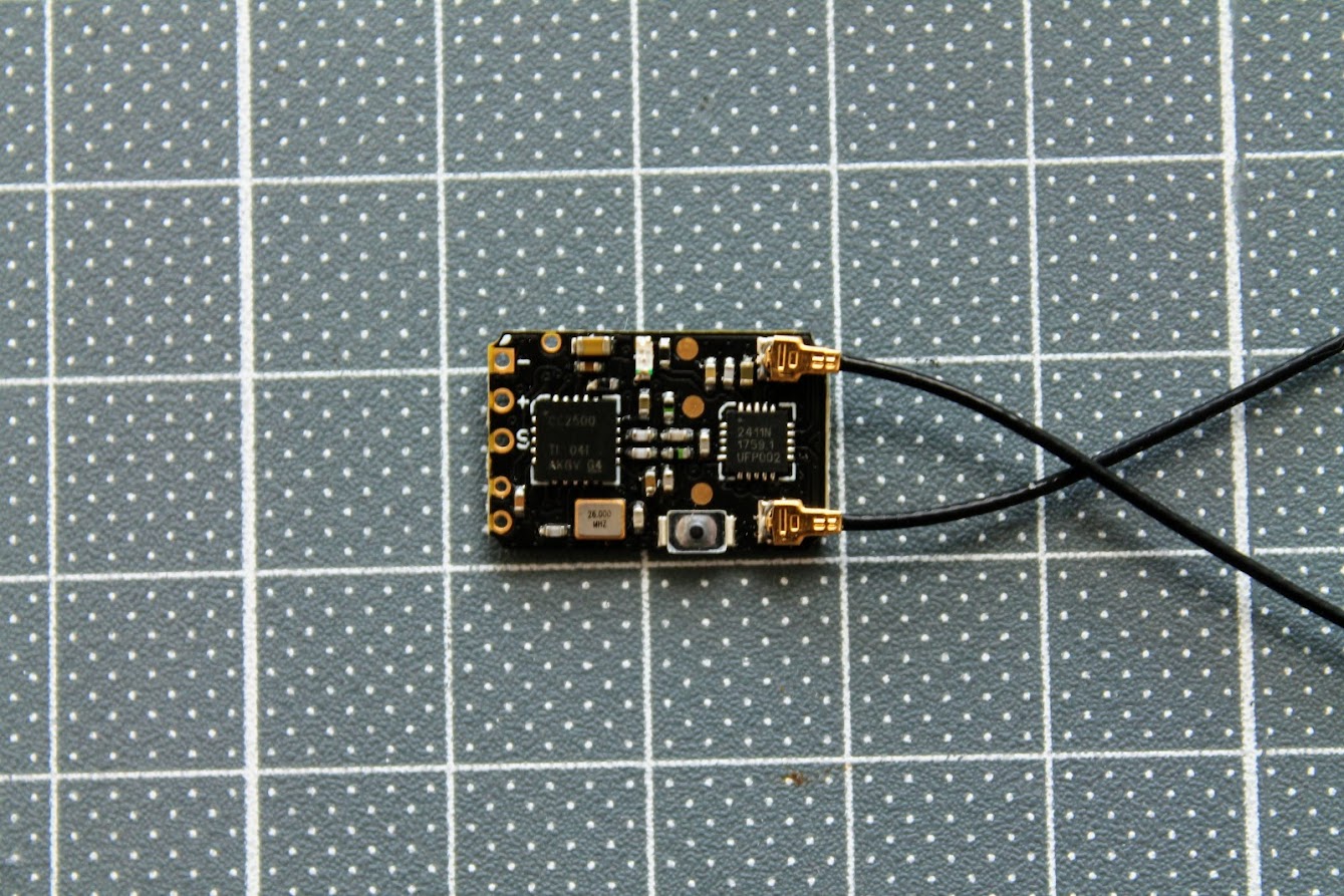
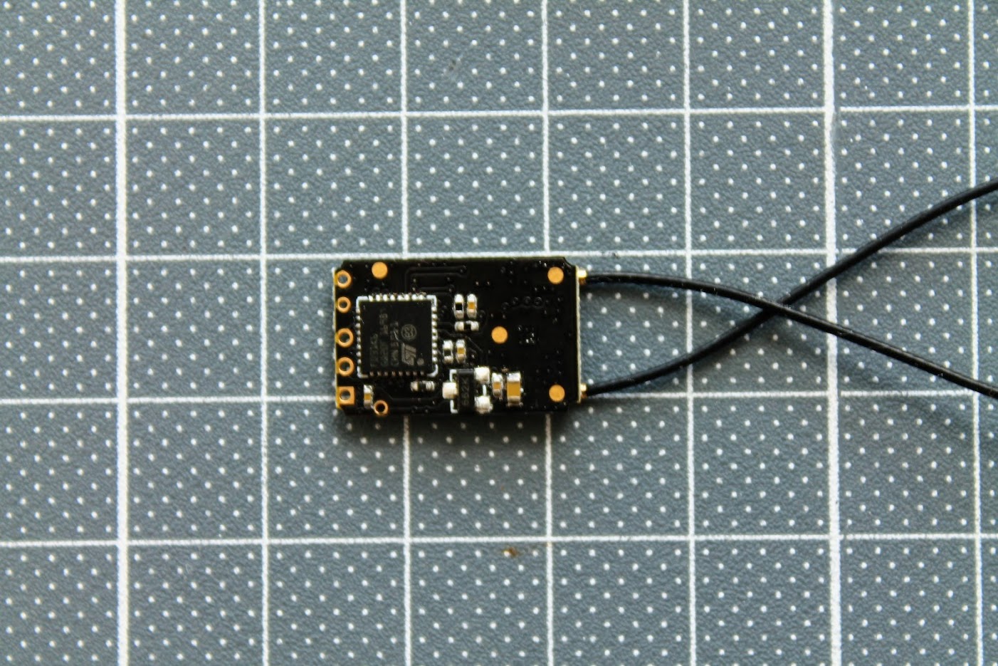
Closer look
Radiomaster R81 is Frsky D8 protocol receiver. This is compatible with the most Frsky radios and with all multiprotocol enabled radios. The receiver size?17x11mm ?is a little bit smaller than Frsky XM+ and a little bit bigger than Frsky R-XSR receiver.
The weight is actually only 0.8 grams with included antennas.
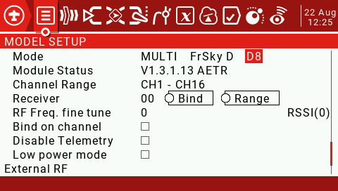
OpenTX setup
Select D8 protocol on the FrSky radio or FrskyX protocol and D8 as subprotocol on the multiprotocol module equipped radios.
Binding
1. Press and hold the BIND button on the receiver then connect power. After approximately 3 seconds, the receiver LED will be RED, the receiver is now in bind mode
2. Select the D8 protocol for the multi-protocol menu of your remote control, and press the [BIND] option, the red light of the receiver will flash indicating successful bind
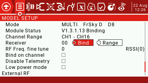
3. Exit bind mode on your remote control and disconnect power to the receiver then power the receiver once more. The LED will now be solid RED indicated the bind is now done. If not please repeat step 1 and 2
Fail-safe Protection
1. Press the BIND button once within 10 seconds of the receiver being powered on, and the receiver will save all the current channel values of the remote control as the fail-safe value
2. 10 seconds after the receiver is powered on, the BIND button function will be disabled to prevent accidental changes to to the fail-safe settings while preparing the model for flight
RSSI output
This receiver has a total of 9 channels. This includes 8 channels for radio control and one channel for the RSSI output.
Channels 1-8 are controlled by the remote controller (radio), but the 9th channel is the signal strength RSSI value output by the receiver itself, which can be read by the flight controller and sent to the OSD device to show?signal strength on the FPV feed.
Frequency tuning
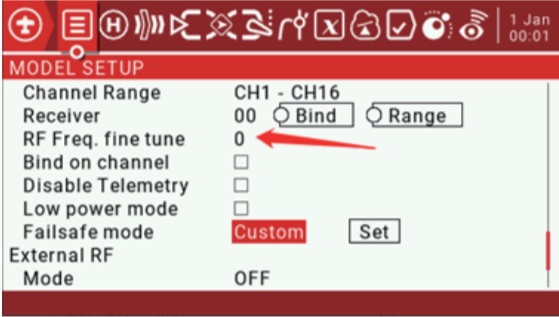
D8 and D16 compatible receivers MUST be frequency fine tuned before flight.
Once the radio is bound to the receiver:
Return to the RF Freq. fine tune option
1. Lower the value until the radio loses the connection with the receiver. Record the value (TUNE_MIN).
2. Raise the value so that the connection is restored, then continue to raise it until the radio loses the connection with the
receiver again. Record the value (TUNE_MAX).
3. Calculate the median between the two values (TUNE_MIN + TUNE_MAX) / 2 = TUNE_MEDIAN
4. Set RF Freq. fine tune to the median value
Example
Connection is lost at -73 and +35; the median is -19:
Once the Fine Tuning value is known, it can be used for all models which use the same protocol.
For More information visit https://www.multi-module.org/using-the-module/frequency-tuning
Betaflight setup
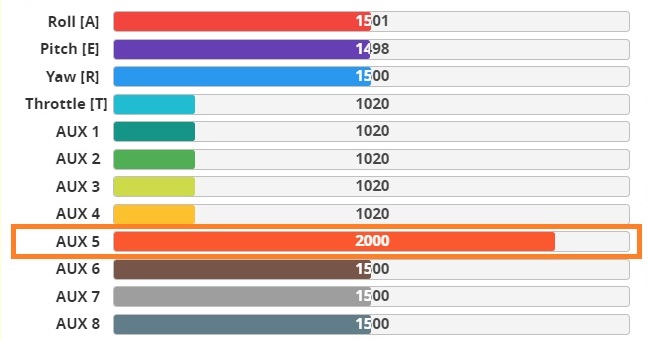
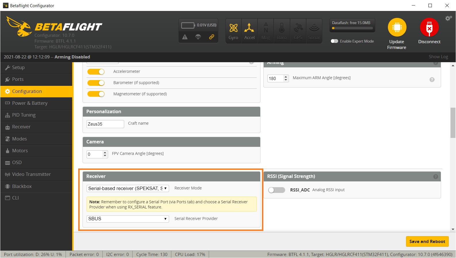
Select Serial-based receiver in the Receiver Mode selection and SBUS as Serial Receiver Provider?in the Configuration tab.
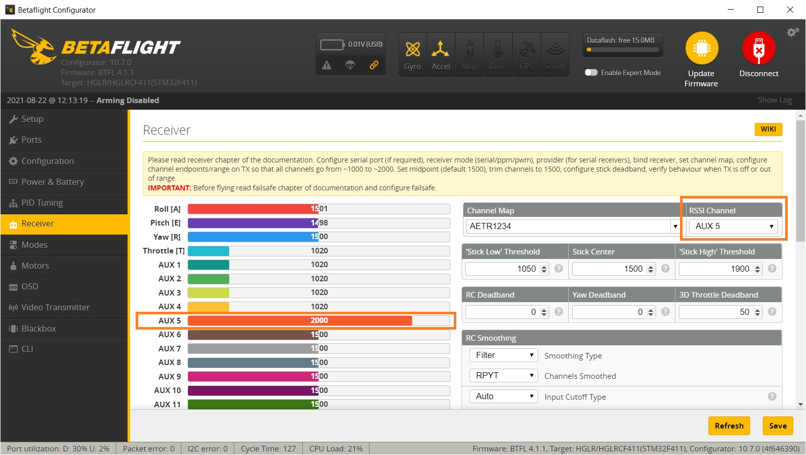
In the Receiver tab You can see the RSSI output on the Channel 9 (AUX5). Set the RSSI Channel to AUX5 respectively to get the RSSI values on the OSD.
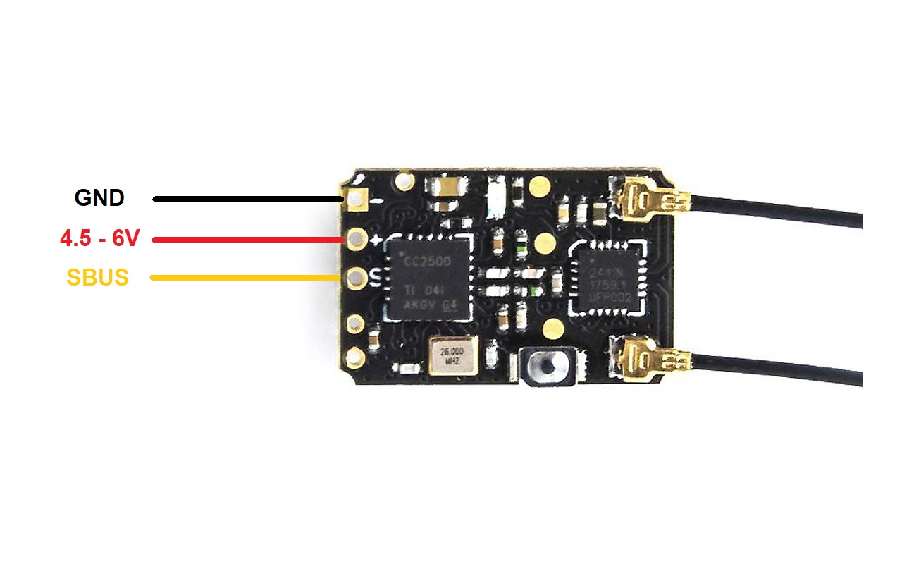
Connection diagram
Radiomaster R81 receiver User Manual:?https://www.radiomasterrc.com/data/article/1611557935016752426.pdf
Available @
Banggood:?https://www.banggood.com/RadioMaster-R81-2_4GHz-8CH-Over-1KM-SBUS-Nano-Receiver-…-1757296.html
GetFPV:?https://www.getfpv.com/radiomaster-r81-8ch-frsky-d8-compatible-nano-receiver-w-sbus.html
]]>
OpenTX version 2.3.14 release
OpenTX version 2.3.14 was released. You should update to this version if you don’t want?Real Time Clock battery?to drain prematurely. Here are the release notes:
ALL RADIO
fix excessive RTC battery drain (Bug affecting all radio model, introduced in 2.3.0, thx MikeB for spotting this)
ACCESS RADIO
fix possible jerky servo movement
X9D + 2019 RADIO
fix trainer mode change potentially triggering emergency mode
fix trainer jack detection
MISCELLANEOUS
fix AFHSD3 option not available on some radio (x7 / x9d +)
fix AFHSD3 broken on colorlcd radio since 2.3.12
COMPANION
fix curve tip window showing blank
fix Companion Mac OS X not running on some version of Mac OS X
fix negative sign missing for telemetry source formula
ExpressLRS version 1.0.0 release
ExpressLRS released… first version ever! Actually not the first but the software is so mature, that it came out of the Release Candidate state to normal version 1.0.0. The maintenance update 1.0.1 followed shortly. ExpressLRS Configurator was also updated and now it supports updating via WiFi directly from the configurator.
Read more about the ExpressLRS in this guide:?ExpressLRS – Open Source Long Range radio control system – Complete Guide
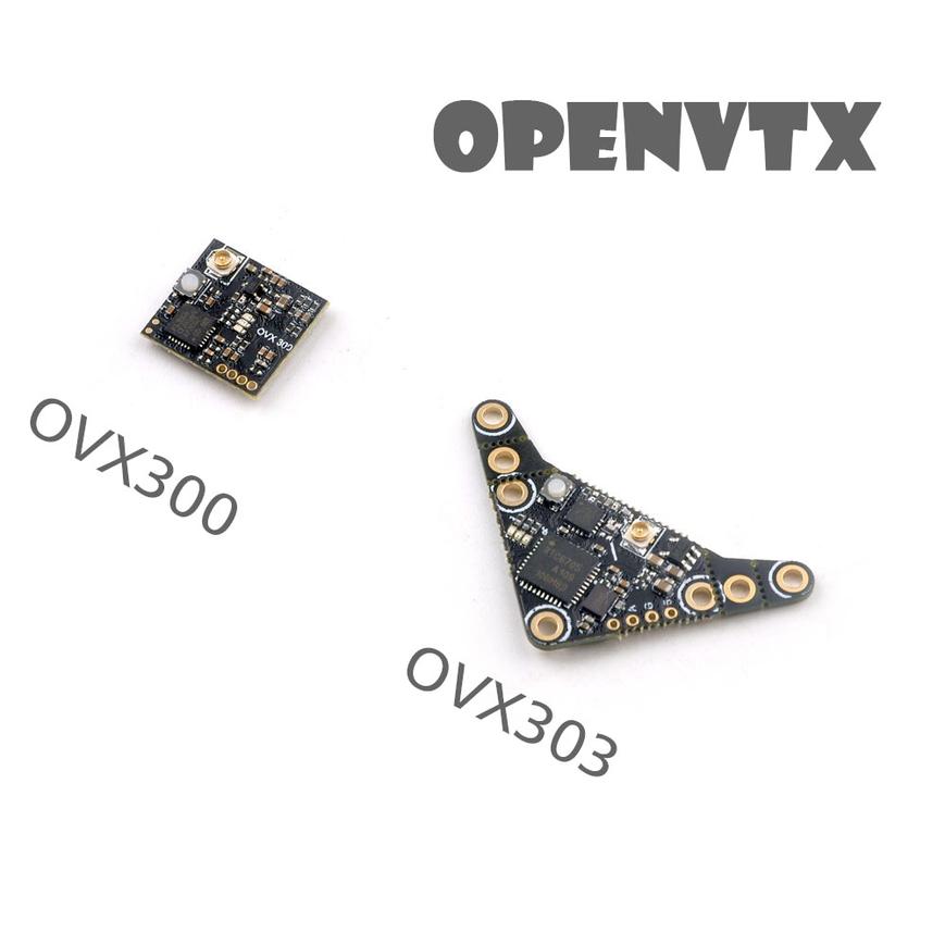
Happymodel OVX300 OVX303 5 VTX Open Source Video Transmitter
Happymodel in collaboration with ExpressLRS devs ha released the first Open Source VTX – OVX300 and OVX303. These two VTXs use Open Source firmware, written by ExpressLRS devs.??OVX300?and?OVX303 are working with the both VTX control protocols – SmartAudio and IRC Tramp. It automatically detects the working protocol and works without any headaches.
Read more about??SmartAudio?in this guide:?Guide: SmartAudio VTX control and how to set it up
Happymodel OVX300 and OVX303 VTX are designed with the ability to have its firmware updated via Betaflight Passthrough.
Available @:
XT-Xinte:?https://www.xt-xinte.com/Happymodel-OVX300-OVX303-5-8G-40ch-300mw-VTX-OpenVTX-p936004.html
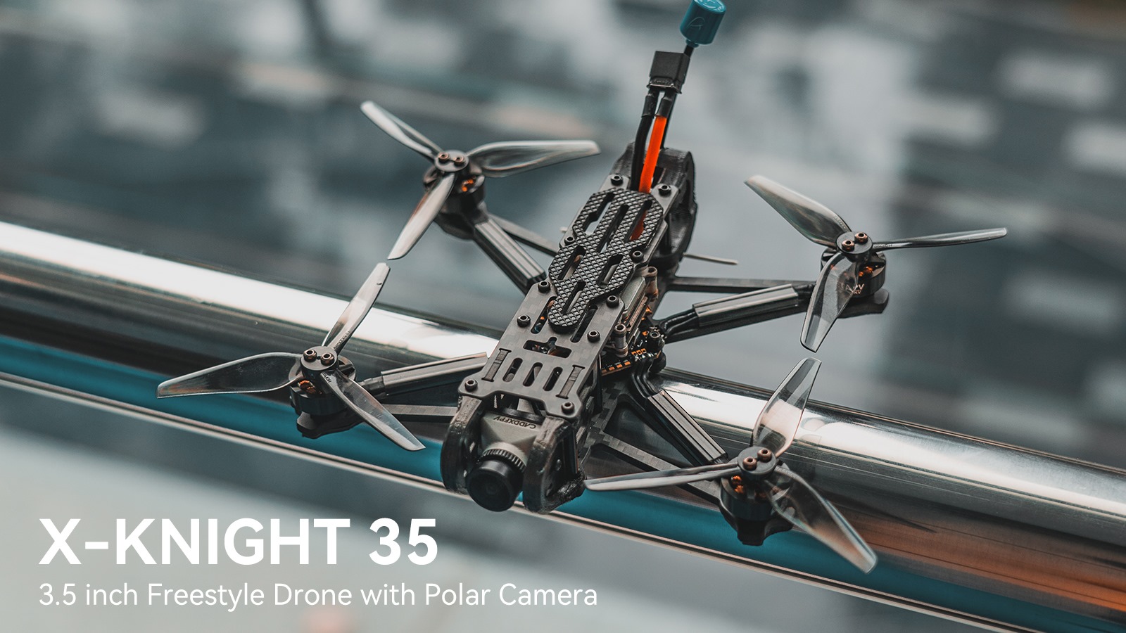
BetaFPV X-Knight 35 quadcopter
BetaFPV X-Knight 35 is the newest release from BetaFPV. It is Ready to Fly freestyle quadcopter with the new 3.5 inch prop size category. It has digital FPV system with?Caddx Polar Vista Kit containing freshly released Caddx Polar digital FPV camera.
Available @
BetaFPV:?https://betafpv.com/collections/x-knight-series/products/x-knight-35-fpv-quadcopter
Specifications:
Item: X-Knight 35 FPV Quadcopter
Weight: 142.9g (Without battery)
Motor: 1404 3800KV Brushless Motors
Power Connection: XT30?
Props: HQ 3520 3-Blade Propellers (Gray) / Gemfan 3520 3-Blade Propellers (Gray)
FC&ESC: F4 AIO 20A Brushless Flight Controller V3
Battery: 750mAh 4S 95C Lipo Battery
VTX&Camera: Caddx Polar Vista Kit (VTX)
FPV Camera Degree: 0°-60°
Diameter: 155m
Receiver: ELRS 2.4GHz Receiver / TBS Receiver
Flight time: 11~13 min smooth flight or 4~6 min flight of FPV freestyle tricks with 4S 750mAh battery
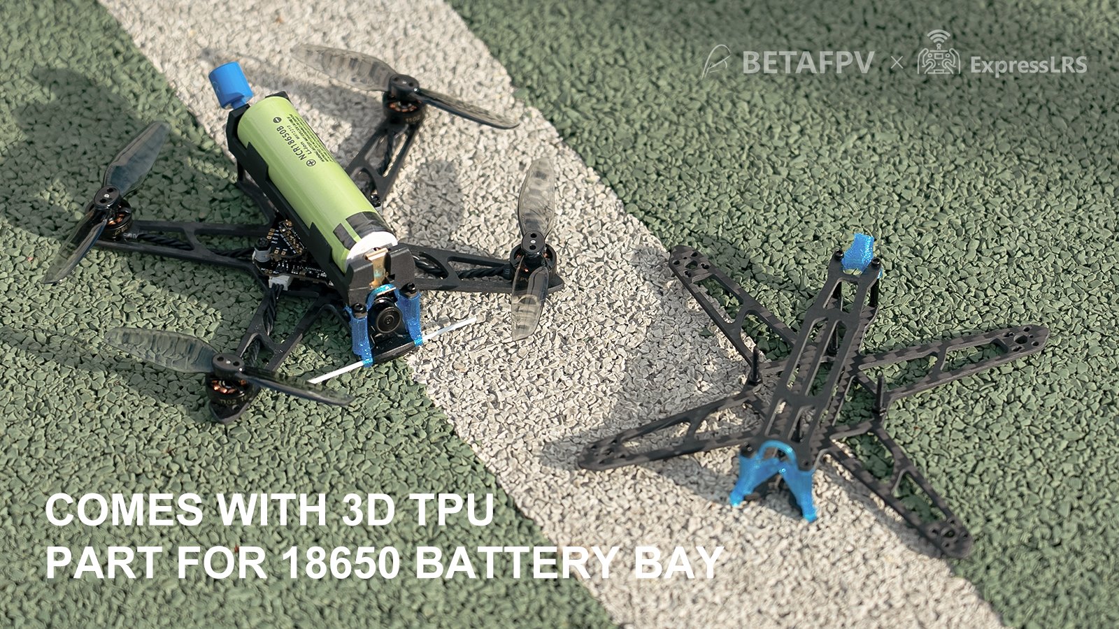
BetaFPV HX115 LR Toothpick quadcopter
BetaFPV also released HX115 LR 1S quadcopter, so called “flying battery”. It has removable battery holder for 18650 type Lion battery and the option to use regular LiPo 1S batteries as well. The BNF HX115 LR quadcopter comes with?12A 1S FC with ExpressLRS RX on board.
Available @
BetaFPV:?https://betafpv.com/collections/expresslrs-series/products/hx115-lr-toothpick-drone
Specifications:
Item: HX115 LR Toothpick Drone
Wheelbase:126mm
Weight:44g
Motor:1102-18000KV
Charge connector:BT2.0 connector
Propeller:HQ 3020 2-Blade Propellers 1.5mm Shaft
Flight controller: F4 1S 12A AIO FC with ELRS 2.4G Receiver
Battery:BT2.0 450mAh 1S Battery
VTX: M02 25-350mW 5.8G VTX
Camera:Caddx ANT camera
Camera Tilt Degree:0-60°
Receiver:Built-in ExpressLRS 2.4G Receiver
Flight time:3-5min with BT2.0 450mAh 1S Battery / 15min+ with Sony VCT6 3000mAh battery
BetaFPV?F4 1S 12A AIO Flight Controller
New 1S AIO toothpick board from BetaFPV. This time it supports up to 12A power output and has two options of integrated SPI receivers – ExpressLRS and FrSky receivers. This is the first toothpick board with integrated ExpressLRS receiver.
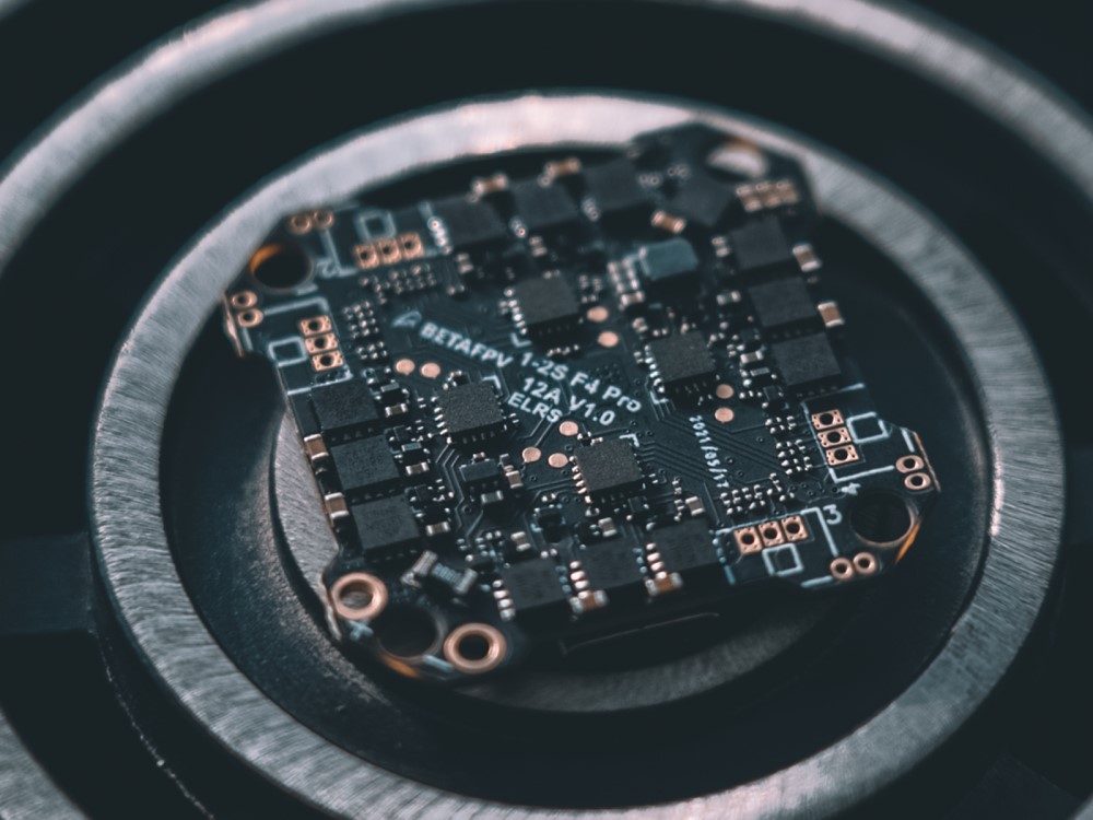
This FC is used in?BetaFPV HX115 LR Toothpick quadcopter.
Available @
BetaFPV:?https://betafpv.com/products/f4-1s-12a-flight-controller
Specifications
Item:?F4?1S?12A?AIO?FC (Frsky)
CPU:?STM32F411CEU6?(100MHZ?)
Gyro:?MPU6000?(SPI?connection)
Firmware?version:?betaflight_4.2.0_STM32F411
OSD:?Built-in?BetaFlight?OSD?(STM32?controls?OSD?chip?over?SPI?in?DMA?mode)
Receiver:?Integrated?SPI ELRS Receiver / SPI Frsky?Receiver
Motor?Pin?Connecter:?1.25mm?Header?Pins
Mounting?Hole?Size:?26mm?x?26mm (suitable?for?whoop?pattern?mounting?hole)
Weight:?4.74 g?(without?power?cable?and?BT2.0?connector)
USB?Port:?Type-C
All modern quadcopters (or any other multirotors) have Arm feature. In order to safely plug in the battery, carry or handle powered multirotor it has to be deactivated (aka Disarmed) and it is the default state of the powered quadcopter. In the deactivated state motors will not spin the propellers regardless A quadcopter has to be activated (aka Armed) only when a pilot is ready to control it.
What is PreArm and why should we use it?
PreArm feature is used for preventing of the accidental arming your quadcopter. You can easily arm the quadcopter by unintentionally hitting the arm switch. Especially if your radio transmitter is hanging on your neck by lanyard. And this happens. I’m not an exemption, I also had unexpected unintentional arming of the quadcopter, happily it ended well. Arming the modern powerful quadcopter with the motor power of several Kilowatts is dangerous thing and can lead to serious injuries.
So unless you are flying whoops with ducted fans or small toothpicks it is advised to set the PREARM mode for your quadcopter.
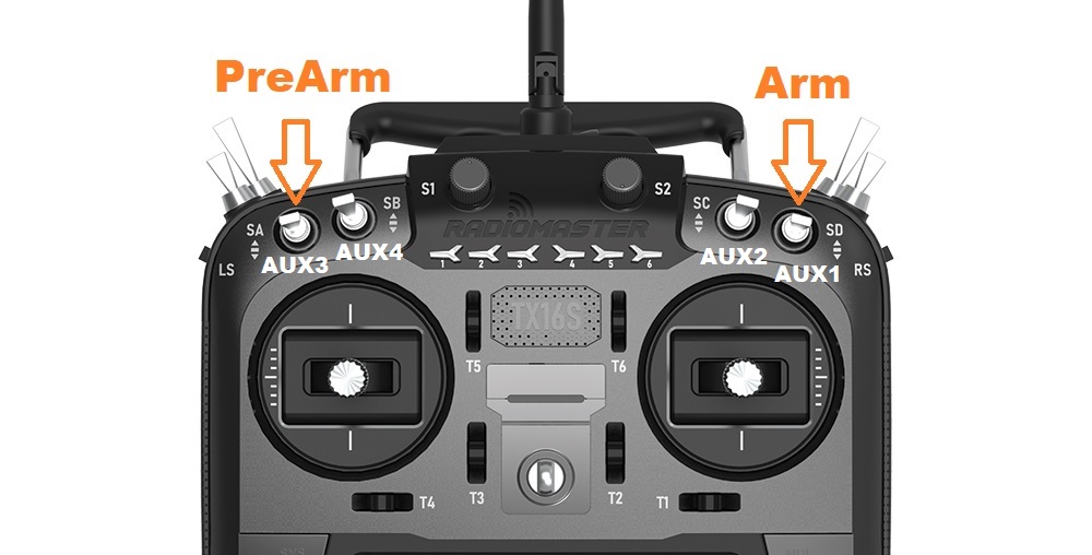
How to setup Arm and PreArm modes to the radio switches?
First you have to set the Inputs and Mixes on your radio transmitter, Model settings. My preferred switch settings are the following and the setup example is based on this configuration. You can customize the Arm and PreArm switches to your preferences.
These are the INPUTS ant MIXES configuration on my OpenTX Radio.
 |
 |
Connect your quadcopter to the Betaflight Configurator. Go to the Modes tab.
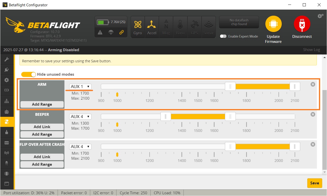
Press Add Range button on the ARM mode selector. Select the AUX channel that corresponds your preferred ARM switch or set it to AUTO and turn On-Off the preferred switch. Configurator will auto detect the switch you are toggling. Slide the sliders to the value range you want the ARM position to be active.
The following example of the configuration has ARM mode on the upper range of the AUX1 channel.
The same procedure is for PREARM mode.
Usually the PREARM switch should be the switch on the opposite side of the radio to minimize the chance of accidental switching on if you bump one side of the radio or you unintentionally hit the switch while the radio is on.
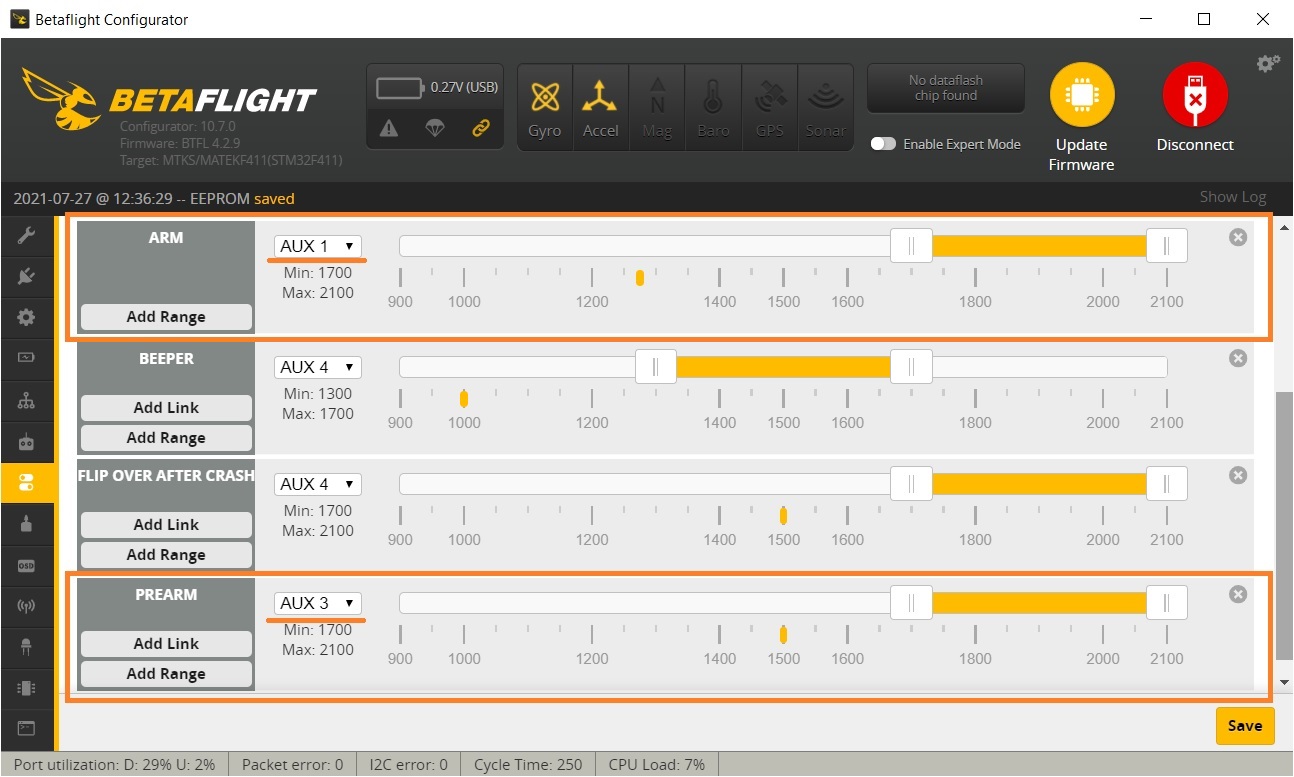
Press Add Range button on the PREARM mode selector. Select the AUX channel that corresponds your preferred PREARM switch or set it to AUTO and turn On-Off the preferred switch. Configurator will auto detect the switch you are toggling. Slide the sliders to the value range you want the PREARM position to be active.
The following example of the configuration has ARM mode on the upper range of the AUX1 channel and PREARM on the AUX3.
Notes
If you turn the ARM mode switch on and your quadcopter does not activate, your props are not spinning and your quadcoper cannot be ARMED, then look at this tutorial on how to troubleshoot the arming problems: Guide: Troubleshooting arming issues
]]>
Will be available @
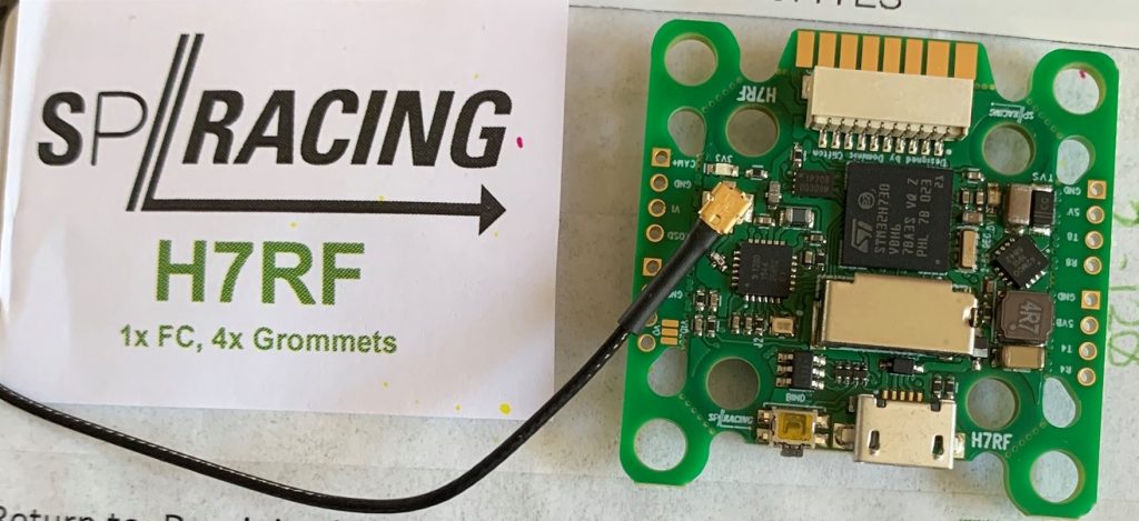
SPRacing: https://shop.seriouslypro.com/flight-controllers
SPRacing H7 ERLS FC User manual: http://seriouslypro.com/files/SPRacingH7RF-Manual-latest.pdf
Specifications:
? STM32H730 CPU, 520MHz inc FPU with ECC
? 2.4Ghz RF receiver IC directly connected to the CPU via SPI for lowest stick-to-motors latency possible. Designed for
ExpressLRS RC system
? SPRacing Pixel OSD with customizable layout, profiles and configuration menu system. Double buffered and capable
of 60FPS (NTSC) or 50FPS (PAL)
? Very low-noise ICM42688P accelerometer/gyro (connected via SPI)
? BMP388 High-precision Barometer – bottom mounted for wind isolation (I2C + interrupt)
? 2MByte 16MBit NOR flash via OctoSPI
? MicroSD card slot (SD/SDHC, up to 32GB) connected via 4-Bit SDIO
? High quality 1.4mm thick 6-layer copper gold-plated PCB with snap-off sections
? 2-8S BEC 5V 2A Switching regulator.
? TVS protection diode.
? High-current 3V switching regulator with extra filter capacitors for sensors
? Buzzer circuitry
? RSSI Analog and PWM circuit
? 8 motor outputs with 2 4in1ESC connectors (JST-SH 10pin)
? 4 sets of 2mm pitch break-out through holes for stacking VTXs or other peripherials
? 1x SPI breakout onto stacking connector
? 5 Serial Ports (4x TX+RX + 1x TX only bi-directional for ESC Telemetry)
? 4 LEDs for 5V, 3V and STATUS A/B (Green, Blue, Red, Orange)
? 37x37mm PCB with 30.5mm and 20mm mounting hole patterns
? 27x27mm PCB after break-off PCB sections (left/right/bottom) are removed
? 4mm mounting holes for soft-mount grommets and M3 bolts
? MicroUSB socket for configuration and ESC programming
Package contents
? Supplied with 4x soft-mount grommets
? Optionally supplied with 2x Audio/Video JST-SH cables. (Camera Input, VTX Output)
? Optionally supplied with IO cables. (for GPS, etc)
? Optional receiver cables for FrSky XSR receivers and 3-pin style receivers available
? 2x sets of 4 solder pads for ESC connections (Bi-Directional DSHOT compatible, 8 motors + 2x TLM + 2x Current)
? 2x sets of 4 solder pads for ESC connections under the connectors! (Same signals as connectors and other pads)
? 4x special solder pads with through-holes for Camera In + Camera OSD
? 4x special solder pads with through-holes for Audio+Video Out (VTX)
? 1x 4 pin JST-SH connector for LED Strip and BUZZER.
? 1x 4 pin JST-SH connector for SWD debugging.
? 1x 12 pin JST-SH connector for 3 UARTS + I2C + 5VBEC + 5V for IO connections.
? 1x 10 pin JST-SH connector for Camera/VTX/UART3/GPIO/Camera Control connections.
? 1x 4pin though-holes for pin headers for UART4 RX/TX
? 1x 8pin though-holes for pin headers for UART8 RX/TX
? 1x 4pin though-holes for pin headers for Camera (GND/Power/Video IN/Camera Control).
? 1x 4pin though-holes for pin headers for VTX (GND/Power/Video OUT/VTX Control (TLM) via UART3).
? 1x Side-press BIND button (top mounted).
? 2x 5V/BATTERY voltage selectors for Camera and VTX outputs
? SP Racing logo
? 1x Additional easter eggs!
Source: Facebook, Discord
]]>