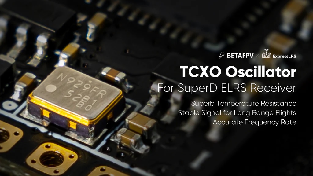
One of the most notorious problems with ExpressLRS hardware is that some manufacturers hardware have unacceptable high frequency error. And in the high or low temperatures it gets even worse. There is certain threshold of the frequency error for the link to work. Up to 40 ppm error (=~100 kHz) frequency difference is considered still acceptable.
Detailed explanation about the Crystal Oscillator (XO) Frequency Error can be found on the expresslrs.org webpage: https://www.expresslrs.org/3.0/hardware/crystal-frequency-error/
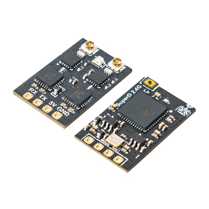
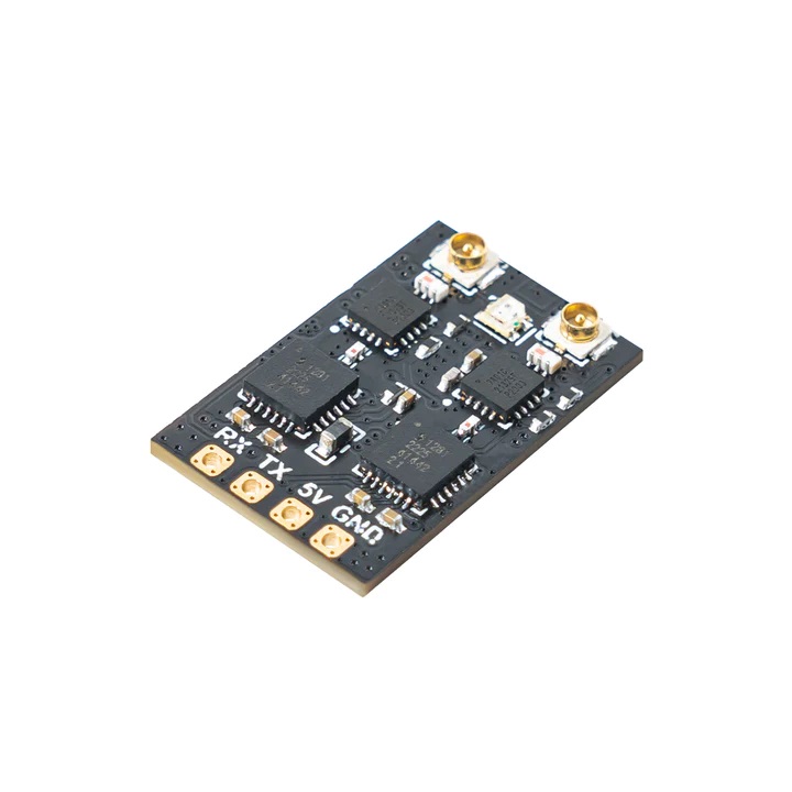
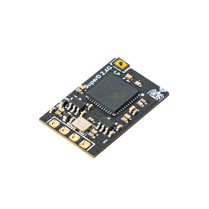
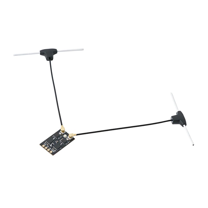
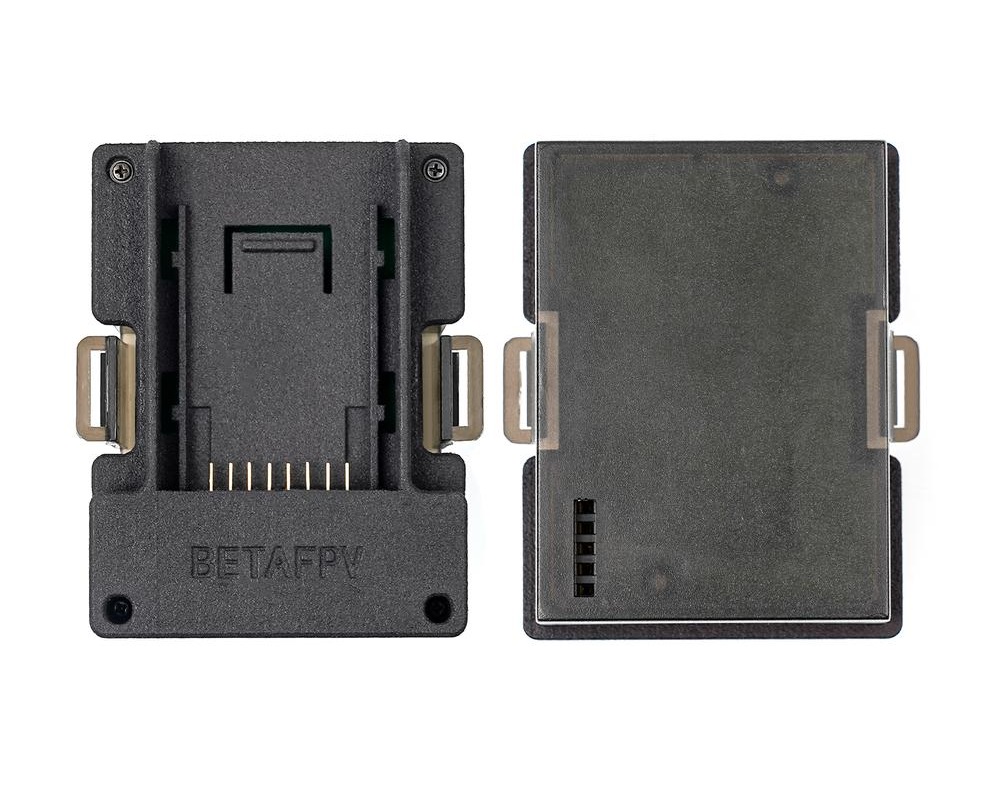
BetaFPV SuperD receiver
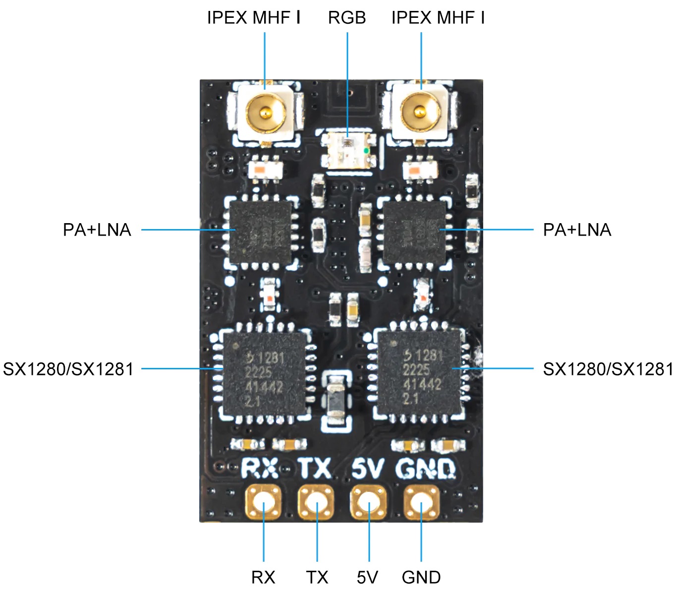
BetaFPV SuperD receiver is the first ExpressLRS receiver with full dual diversity and temperature compensated crystal. Receiver has two SX1280 LoRa RF ICs, two PA/LNA amplifiers and two antenna connectors. Power amplifier provides 100mW for telemetry link.
Available @ BetaFPV: https://betafpv.com/products/superd-elrs-2-4g-diversity-receiver
Aliexpress: https://www.aliexpress.com/item/1005004938838056.html
Specifications
Item: BETAFPV SuperD ELRS 2.4G Diversity Receiver
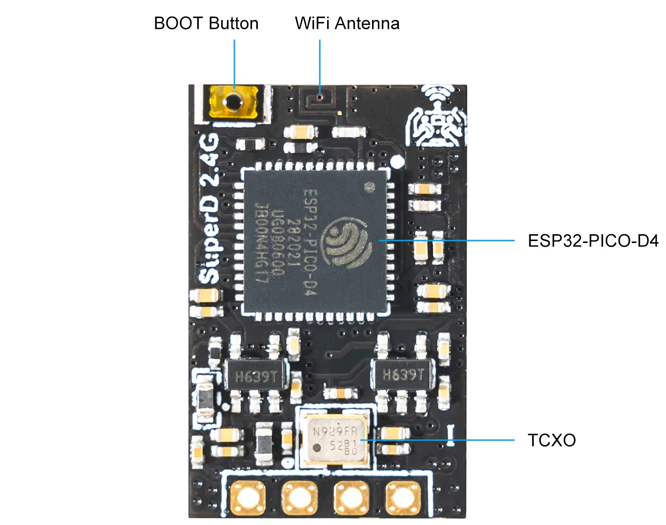
MCU: ESP32 PICO D4, dual SX1280 (SX1281)
Antenna Connector: IPEX MHF 1/U.FL
RF Frequency: 2.4GHz (2400~2480MHz)
Telemetry Power: 20dBm (100mW)
Receiver Protocol: CRSF
Input Voltage: +5V DC @ “+” pad
PCB Size: 22mm*14mm
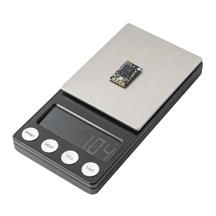
Weight: 1.1g excluding antenna
Crystal oscillator: high-quality TCXO
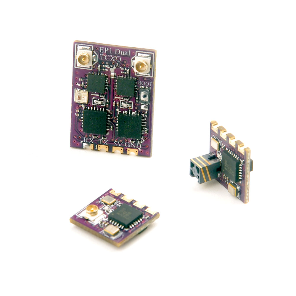
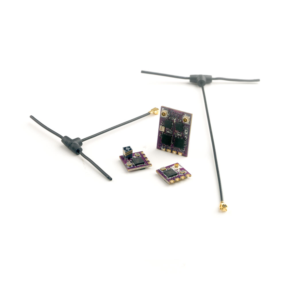
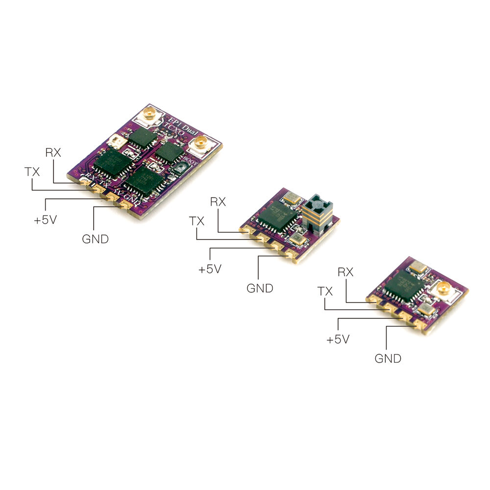
Happymodel TCXO EP1,EP2 and EP1 Dual receivers
Happymodel has also released their three EP1, EP2 and EP1 Dual ExpressLRS receivers with temperature compensated crystals (TCXO).
Available @
Banggood: https://www.banggood.com/HappyModel-EP1-Dual-or-EP1-RCXO-or-EP2-TCXO-…-1975740.html
Makerfire: https://shop.makerfire.com/…/happymodel-ep1-tcxo-and-ep2-tcxo-2-4ghz-expresslrs-receiver-elrs
Aliexpress: https://www.aliexpress.com/item/1005002459298315.html
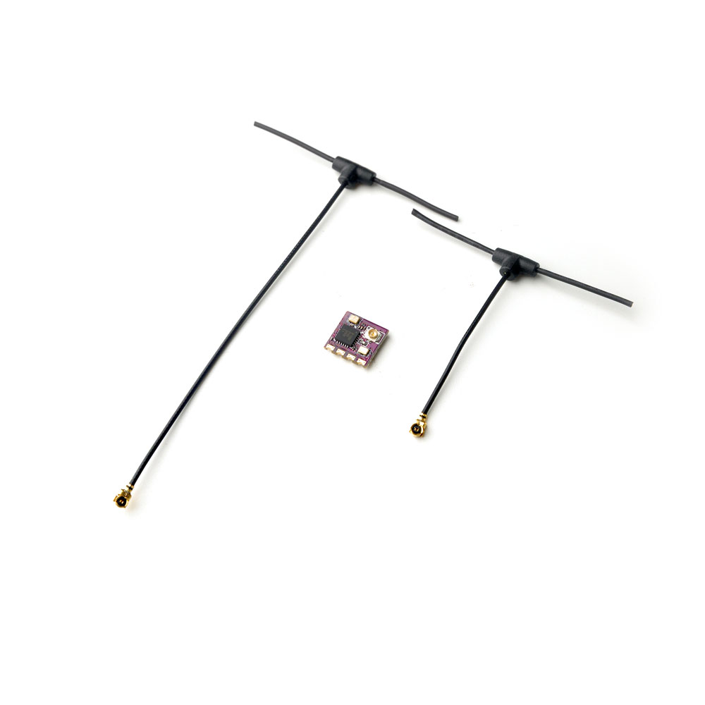
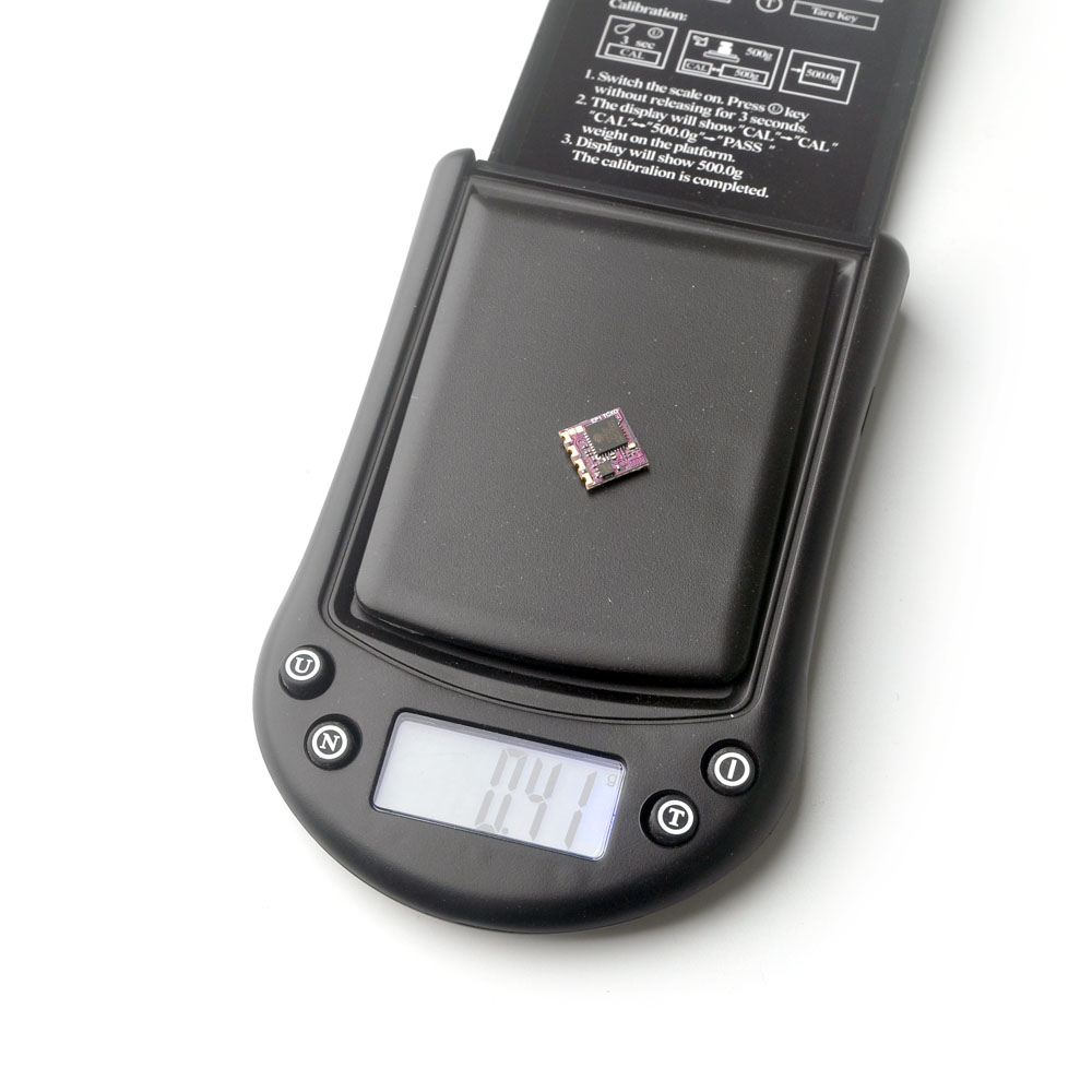
EP1 TCXO Receiver
Type: ISM2.4GHz
ESP8285 MCU
SX1280(SX1281)IMLTRT RF Module
Omni directional antenna
Frequency Range: 2400 MHz to 2500 MHz
Receive refresh rate: 25HZ~500Hz
Working voltage: 5V
Weight: 0.41g (without antenna)
Dimension: 10mm*10mm*6mm
Peak gain: 2.23dB
Default Firmware out of factory: HappyModel_EP_2400_RX V2.2 version
Built-in a TCXO (temperature compensated crystal oscillator)
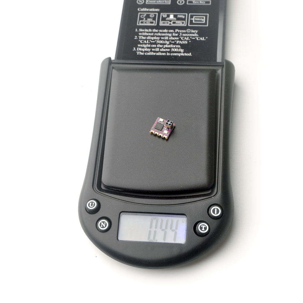
EP2 TCXO Receiver
Type: ISM2.4GHz
ESP8285 MCU
SX1280(SX1281)IMLTRT RF Module
SMD Ceramic antenna
Frequency Range: 2400 MHz to 2500 MHz
Receive refresh rate: 25HZ~500Hz
Working voltage: 5v
Weight: 0.44g
Dimension: 10mm*10mm*6mm
Peak gain: 3.7dB
Default Firmware out of factory: HappyModel_EP_2400_RX V2.2 version
Built-in a TCXO (temperature compensated crystal oscillator)
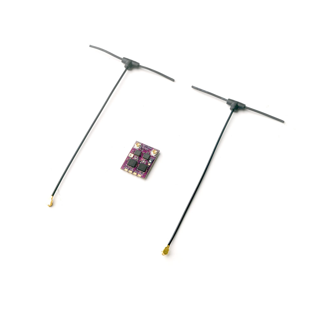
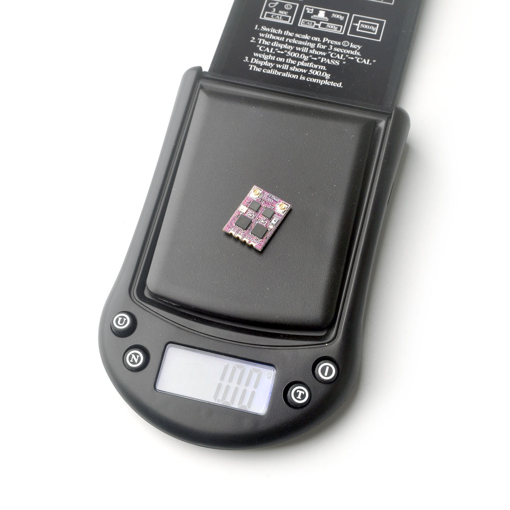
EP1 Dual TCXO Receiver
Type: ISM2.4GHz
ESP32 PICO D4, dual SX1280(SX1281)
Antenna connector: IPEX MHF 1/U.FL
RF Frequency: 2.4GHz (2400~2480MHz)
Telemetry power: >19dbm
Receiver protocol: CRSF
Input voltage: +5V DC @ “+” pad
PCB size: 19mm x 14mm
Weight: 1g (excluding antenna)
Built-in a TCXO (temperature compensated crystal oscillator)
Firmware: HappyModel EP1 Dual 2400 RX (starting from ExpressLRS V3.0)
Both manufacturers dual diversity receivers have multicolored LED for status indication. SuperD and EP1 Dual receiver RGB status indication is shown below.
| RGB Color | Status | Description |
| Rainbow | Fade effect | Power on |
| Green | Quick flash | WIFI upgrading mode |
| Red | Quick flash | No RF chip detected |
| Orange | Double flash | Binding mode |
| Orange | Triple flash | Connected, but mismatched model-match configuration |
| Orange | Slow flash | Waiting for connection |
| Solid on | Connected and color indicates packet rate (see below) |
The RGB light color corresponding to the packet rate

Specifications:
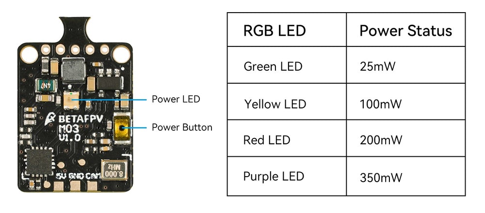
Output power: 25/100/200/350mW (adjustable)
Supply voltage range: 4.5-5.5V
Weight: 1.1g (antenna not included)
VTX internal size: 18x14mm
Frequency: 5.8GHz 48 channels, with Raceband: 5658~5917MHz
Channel SEL: SmartAudio
Modulation type: FM
Frequency control: PLL
All harmonic: Max -50dBm
Frequency stability: ±100KHz (Typ.)
Frequency precision: ±200KHz (Typ.)
Channel carrier error: ±1.5dB
Antenna port: 50 Ω
Operating temperature: -10℃~+80℃
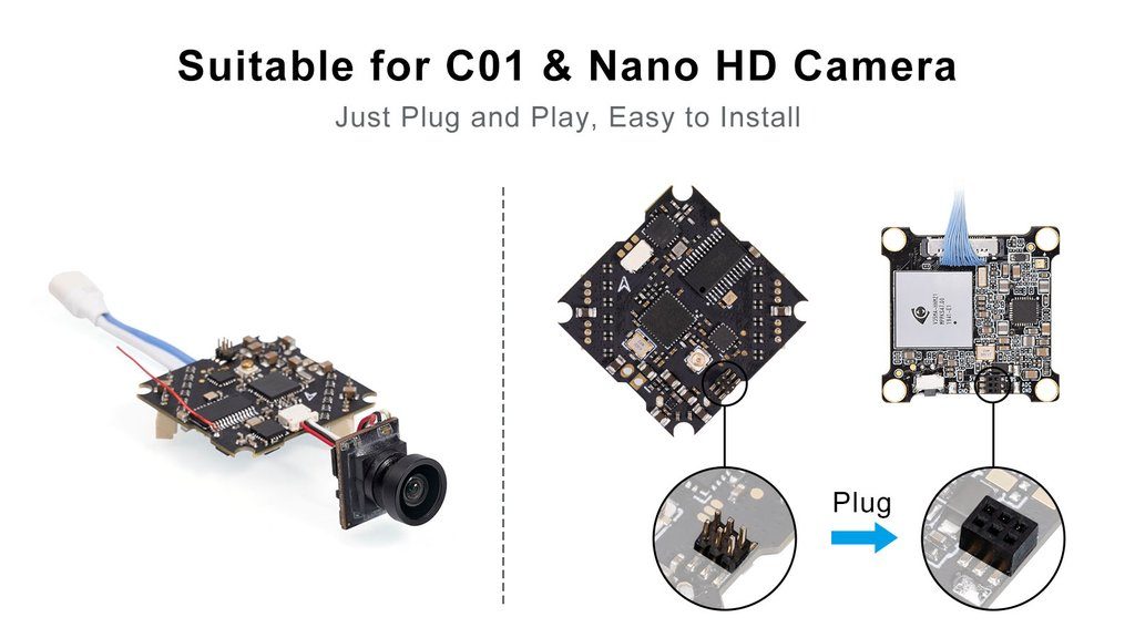
Camera connector: JST-0.8, compatible with camera like BETAFPV C01, BETAFPV C02 and NewBeeDrone BeeEye.
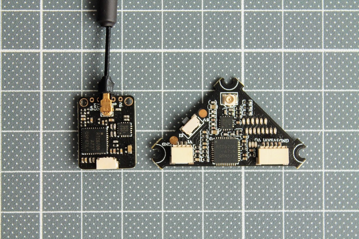
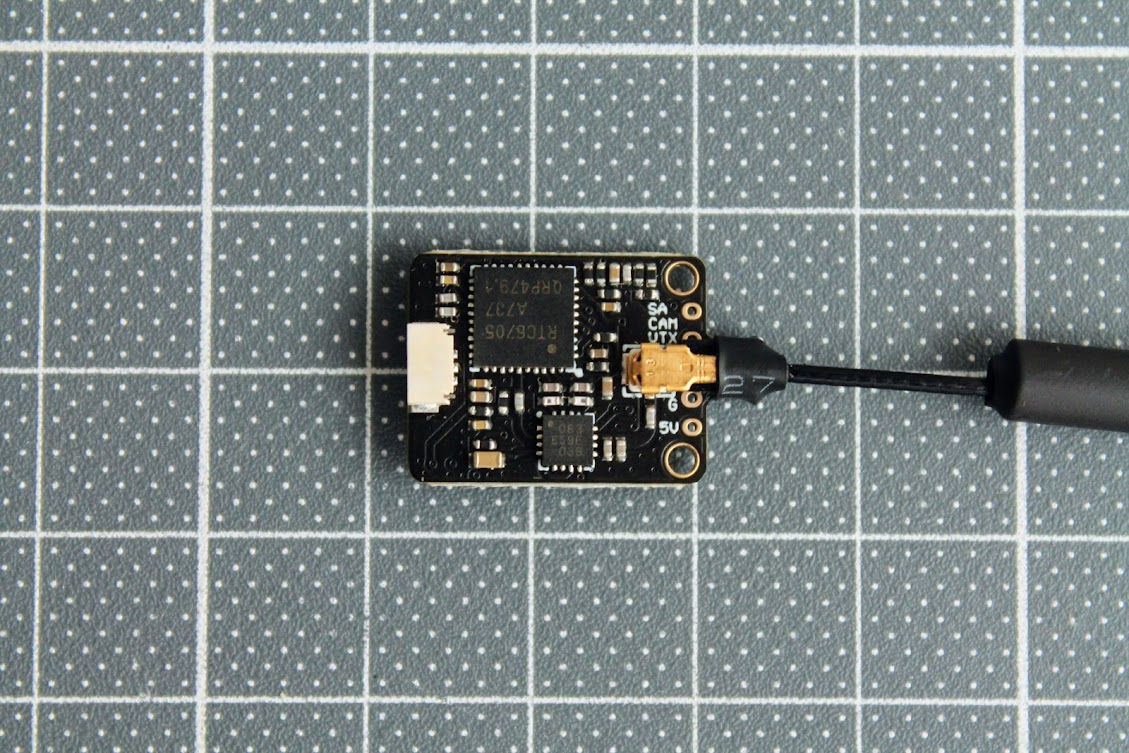
Closer look
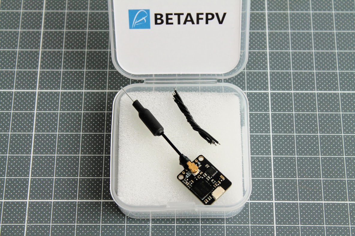
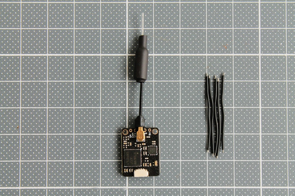
BetaFPV M03 VTX package contains M03?VTX, with linear antenna?and 5 silicone wires for soldering this VTX to the FC.
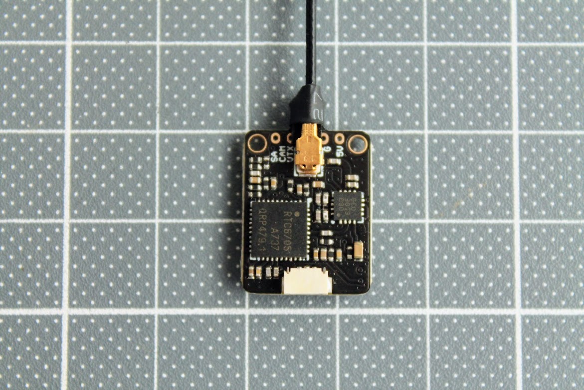
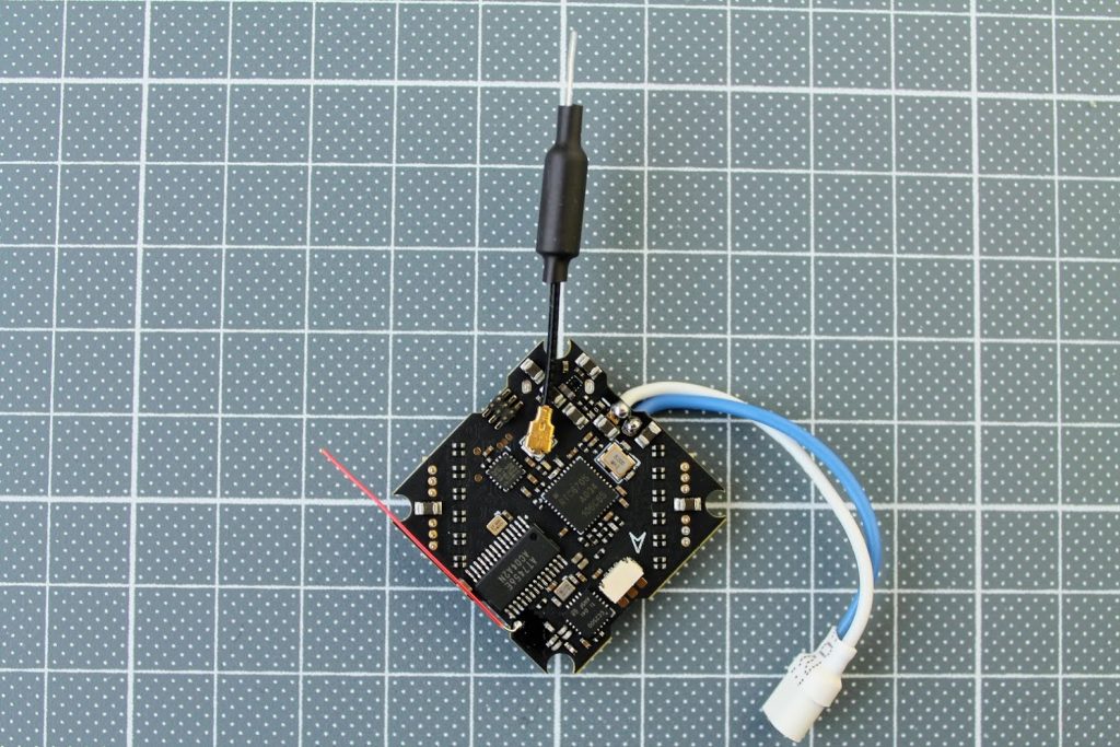
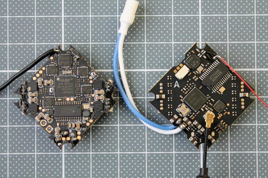
Top side view.
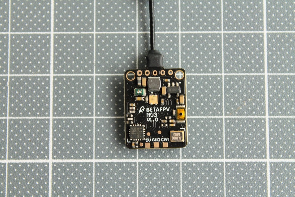
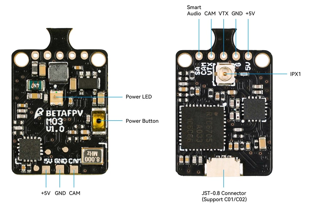
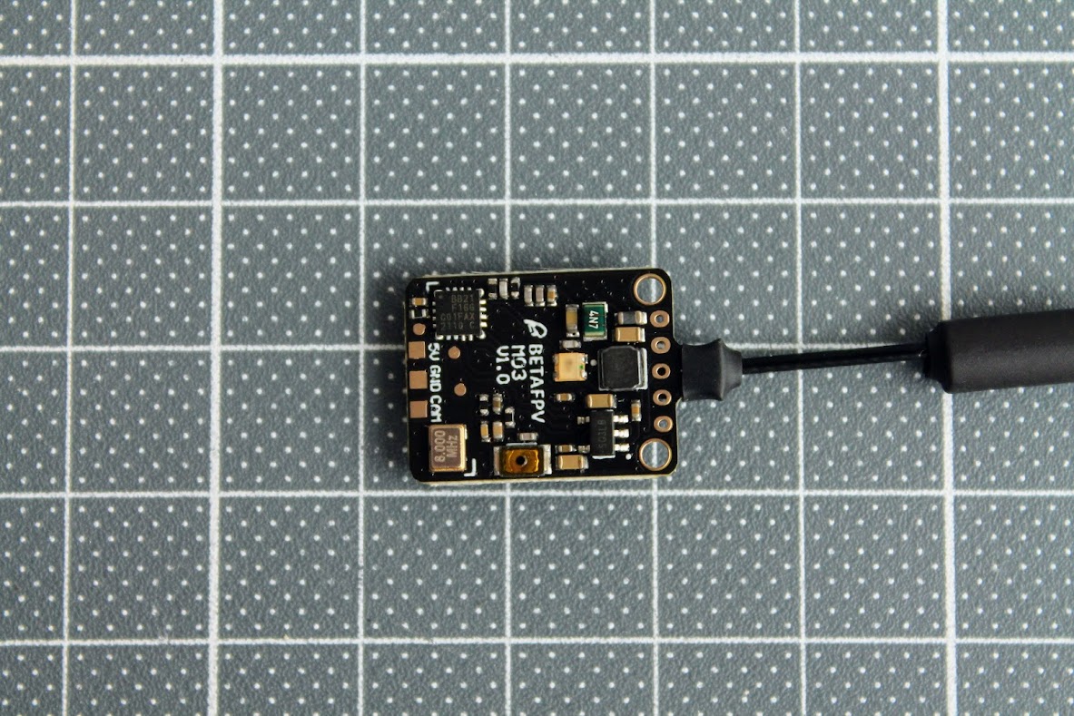
On the bottom side you can find the push button for setting the power output level and the LED for power level output indication.
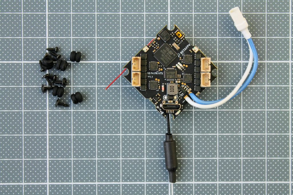
M03 VTX has JST-0.8 connector socket that is direct plug in compatible with BETAFPV C01 (discontinued),?BETAFPV C02?and?NewBeeDrone BeeEye?cameras that have such connector preinstalled. There is also solder pads for soldering the camera vires directly to the VTX.
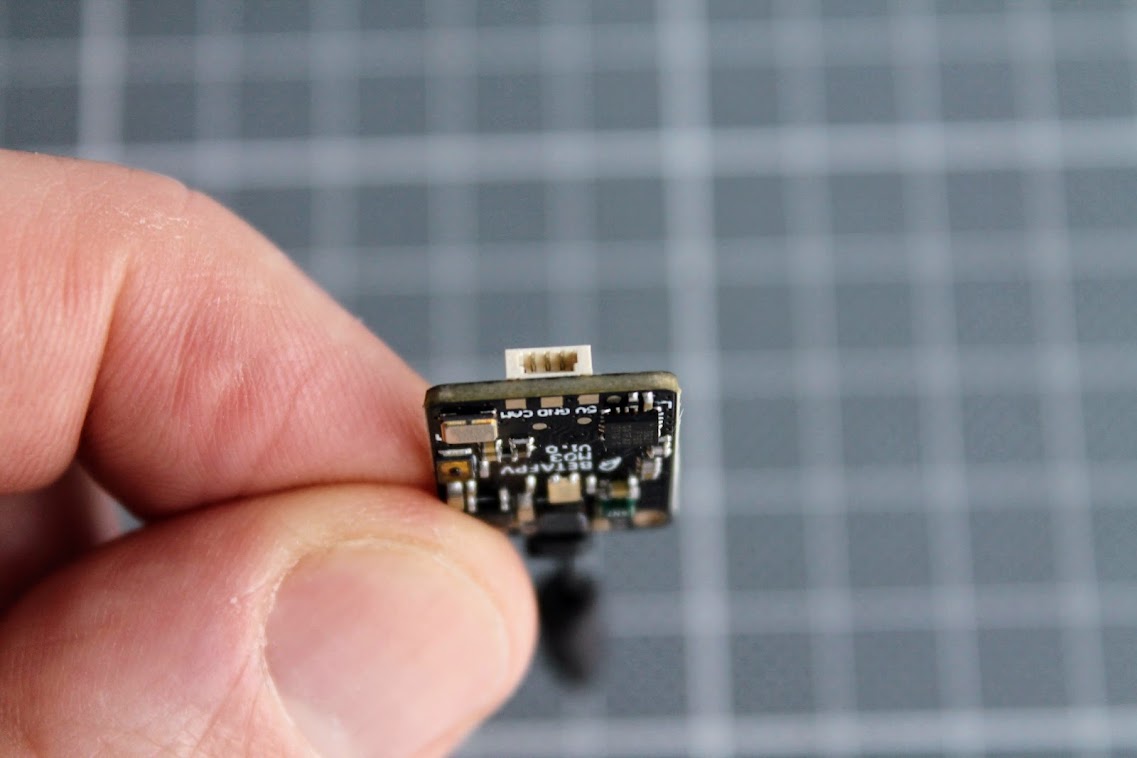
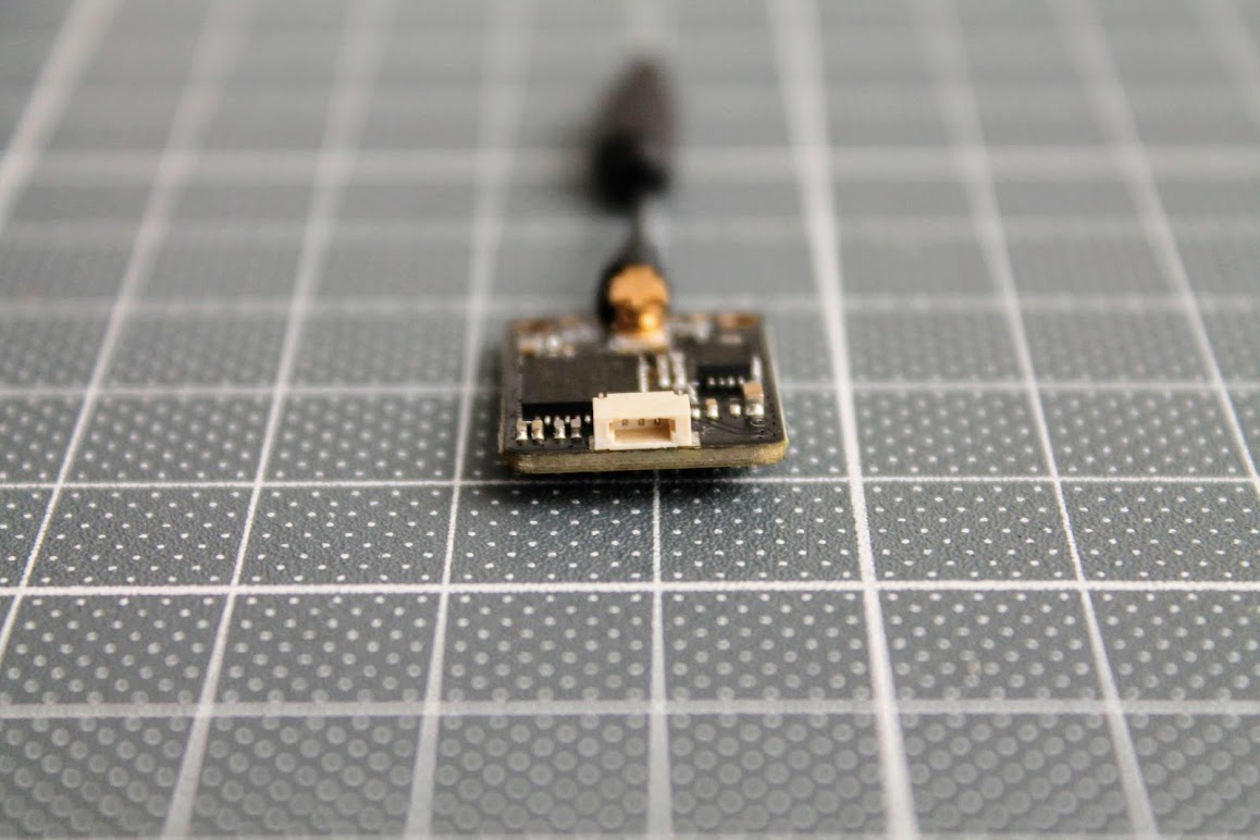
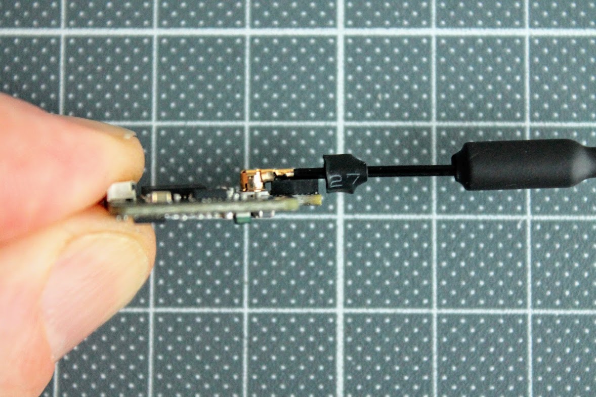
There is a spacer between the antenna and the PCB an the antenna is fixed to the the PCB with small piece of the heat shrink.
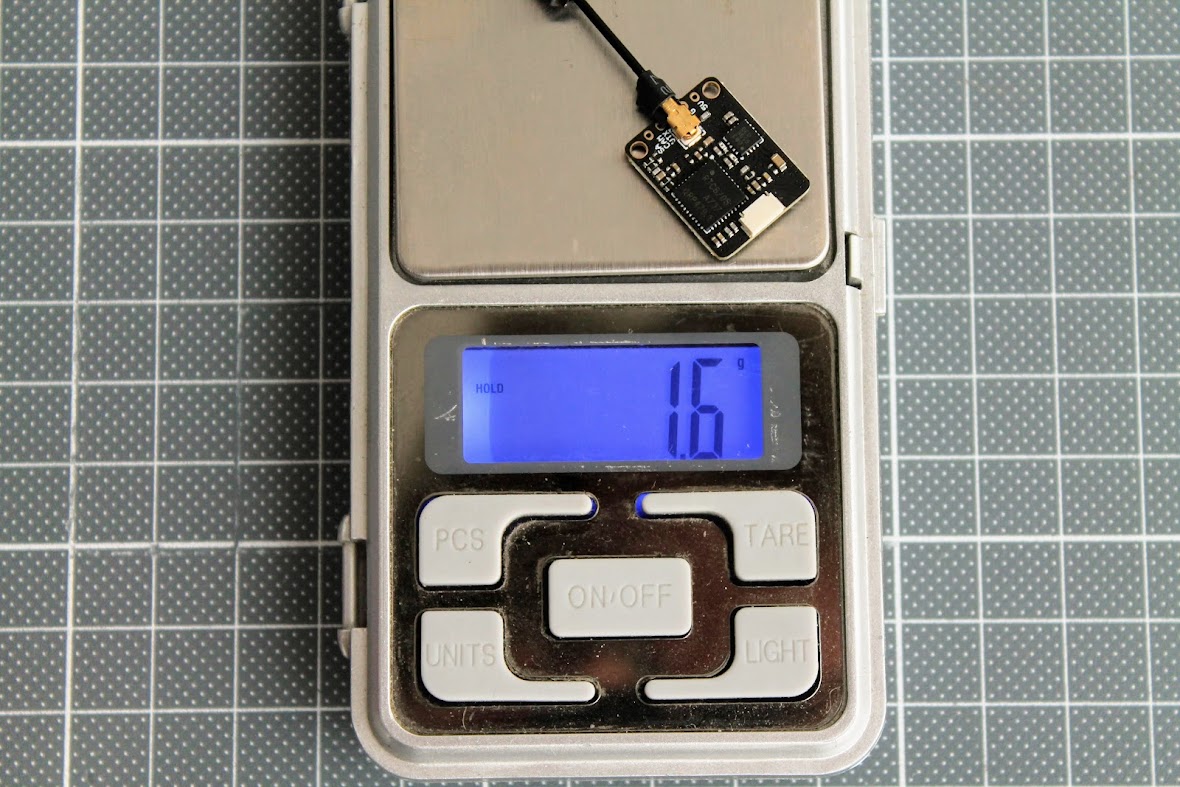
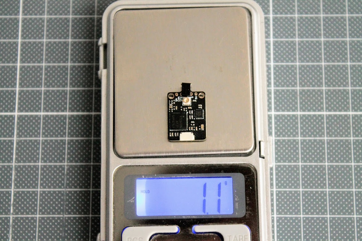
Size and weight
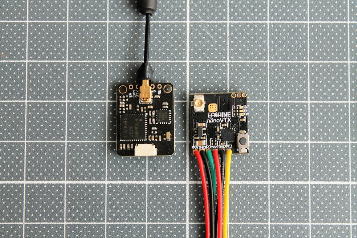
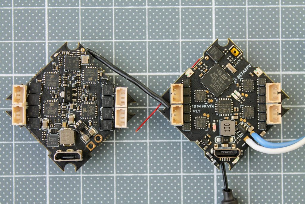
Size comparison with Eachine NanoVTX.
 Size comparison with Happymodel WhoopVTX.
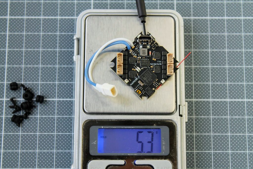
BetaFVP M03 VTX weights 1.6 grams including the antenna.
And weights only 1.1 grams without the antenna.
Pinouts and connection diagrams
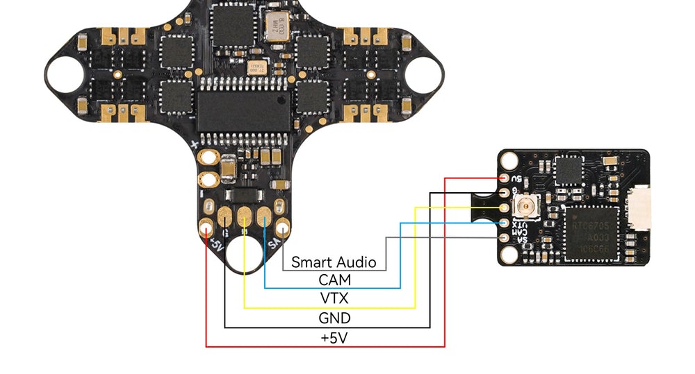
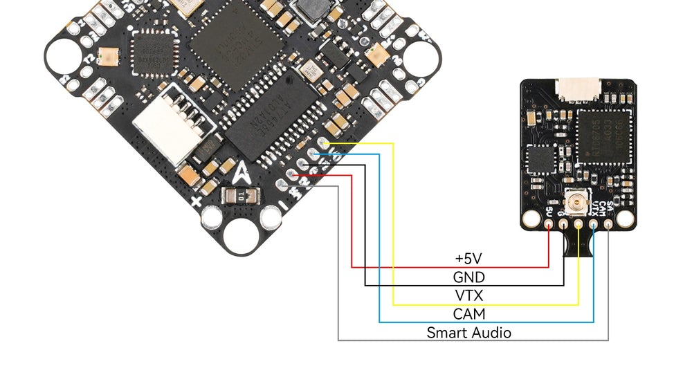
BetaFPV M03?VTX connection pinout
BetaFPV M03 VTX connection diagram
Power output measurements
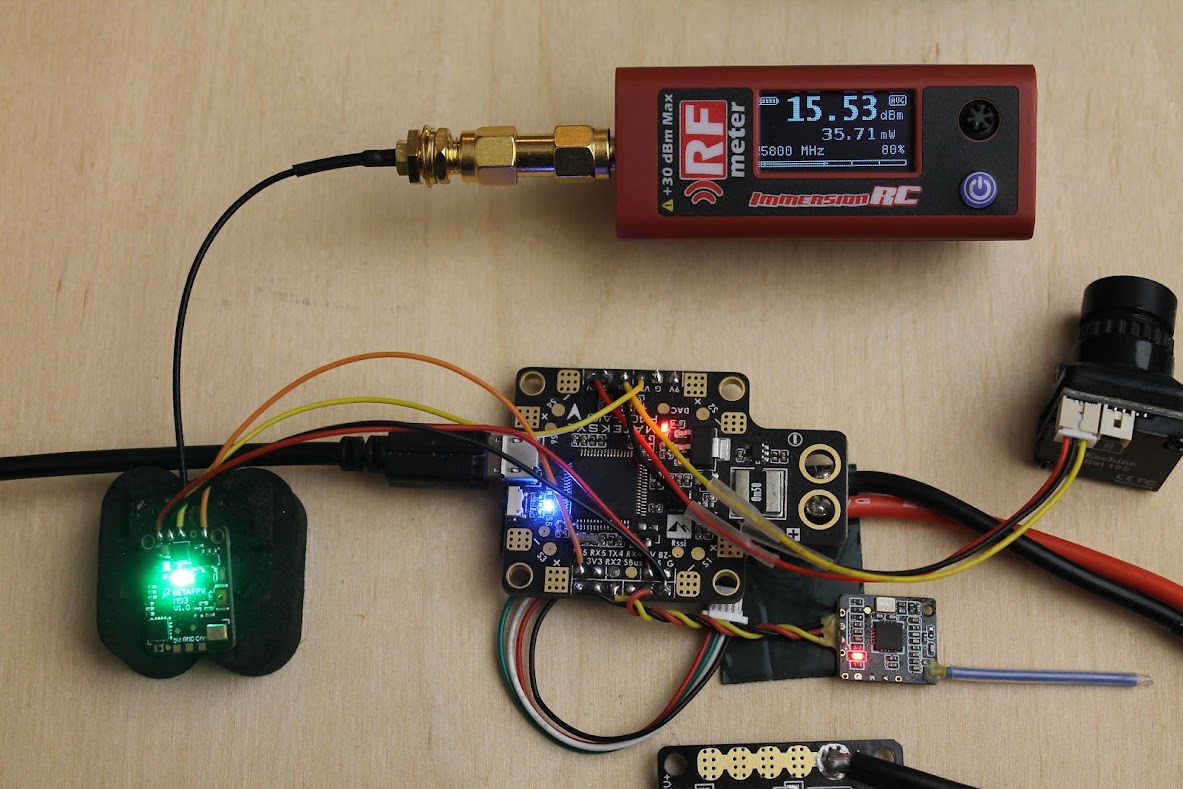
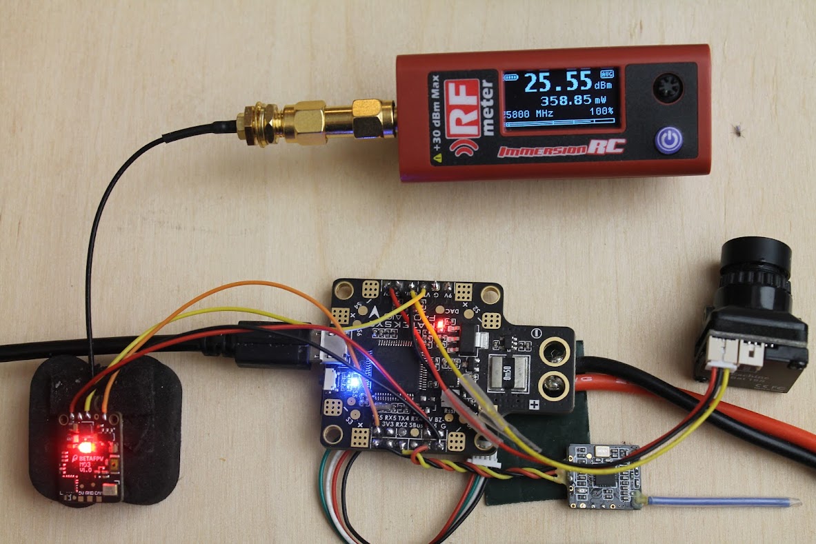
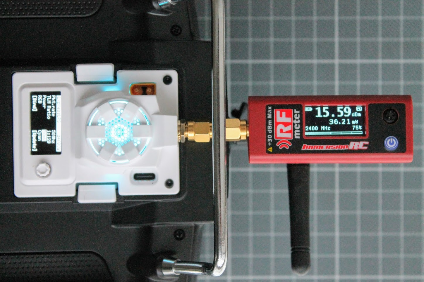
I’ve connected the BetaFPV M03 VTX?to the ImmersionRC RF power meter V2 via short u.Fl to SMA pigtail. VTX was cooled with fan while taking the measurements.
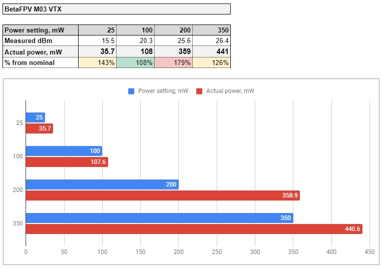
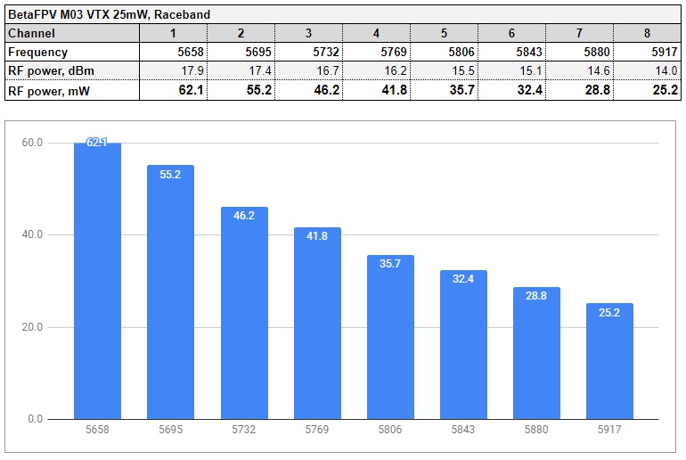
First test –?25mW?output setting. In my test it is outputting about 36mW?(15.5dBm).
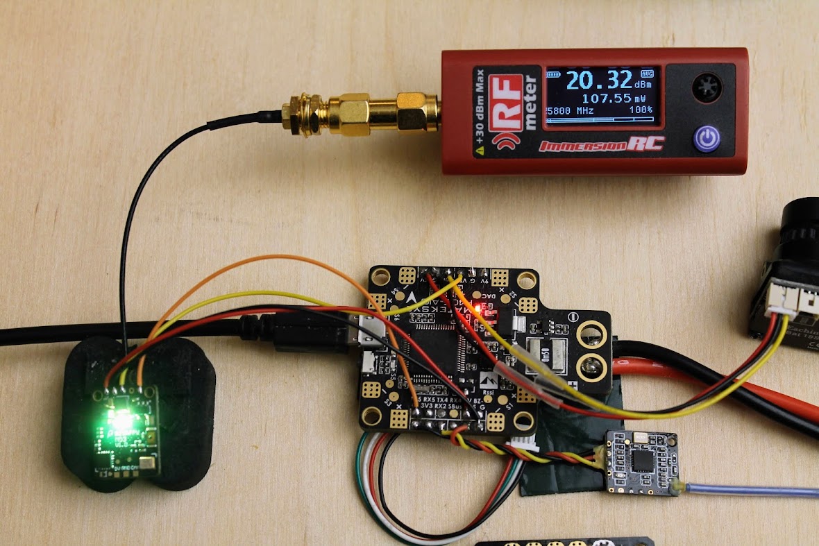
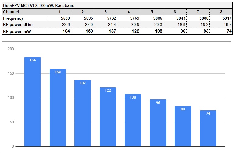
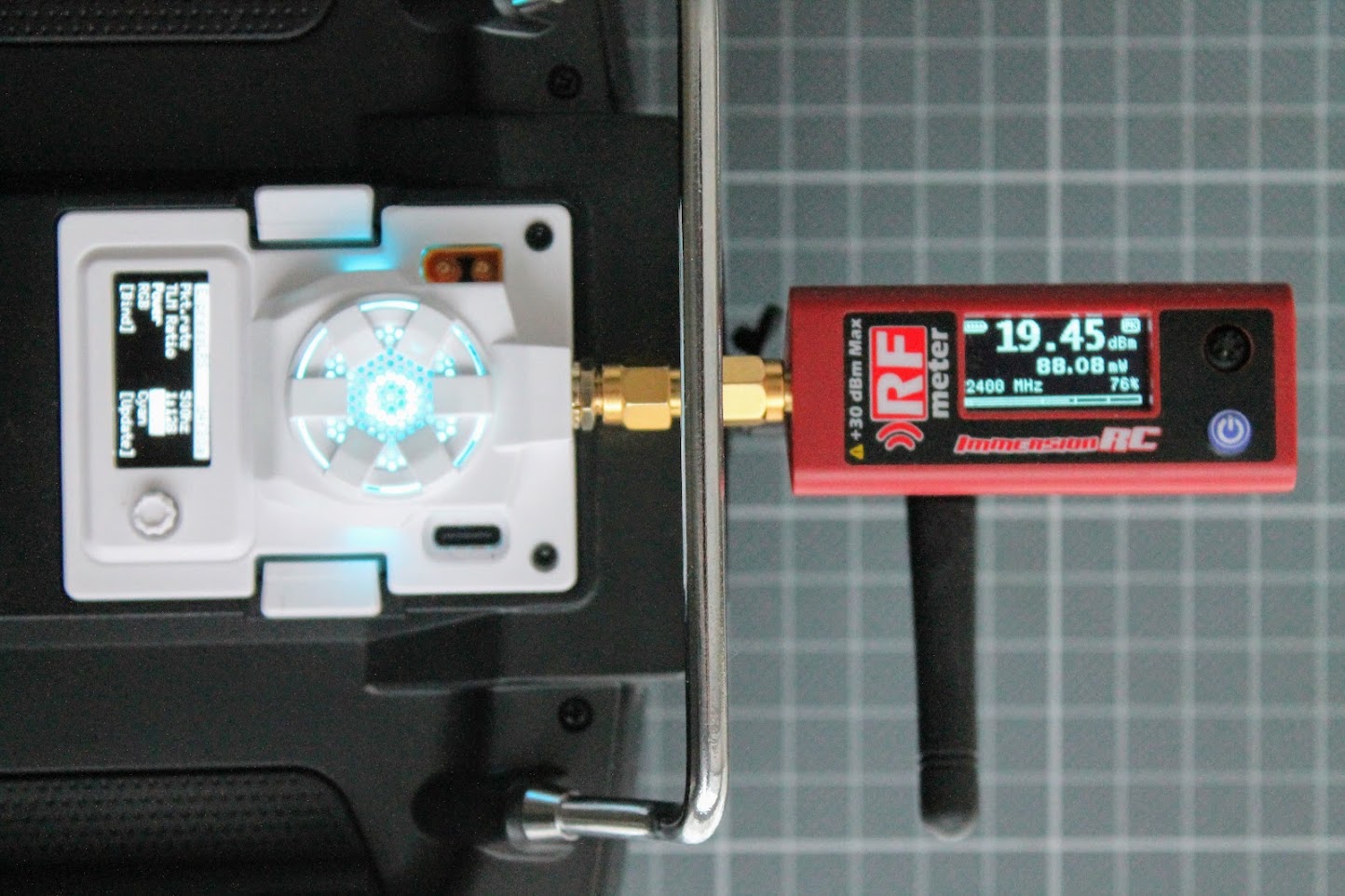
At the?100mW?setting it outputs?108 mW?(20.3Bm). Pretty spot on.
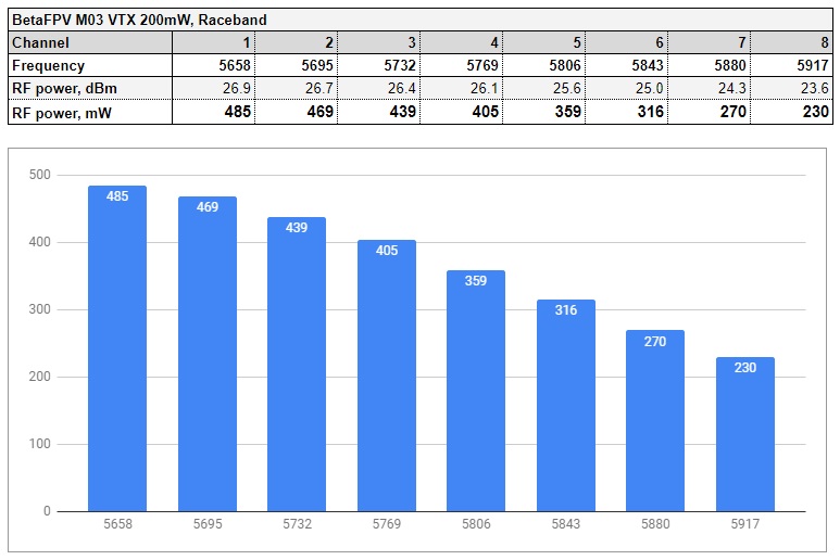
At the?200mW?setting it outputs?358 mW?(25.55 dBm). This is almost double than the nominal power output!
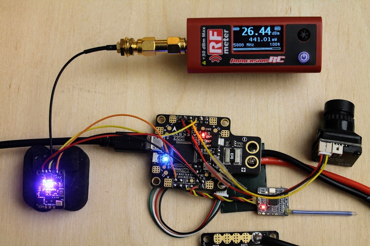
And at the max setting of?350mW?it outputs?441 mW?(26.4 Bm).
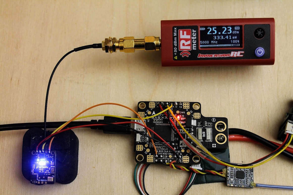
Next test – how stable its power output if the VTX is not cooled actively. So I’ve turned off the fan and let the VTX running for the 5min. The measured power output was 333mW (25.2dBm). Pretty good. The M03 VTX maintains the high power output even without active cooling.
Below are the RF power outputs for all power levels. Measured at?Raceband,?CH5.
Power output vs frequency for?25mW?power level on?Raceband.
Power output vs frequency for?100mW?power level on?Raceband.
Power output vs frequency for?200mW?power level on?Raceband.
Power output vs frequency for 350mW?power level on?Raceband.
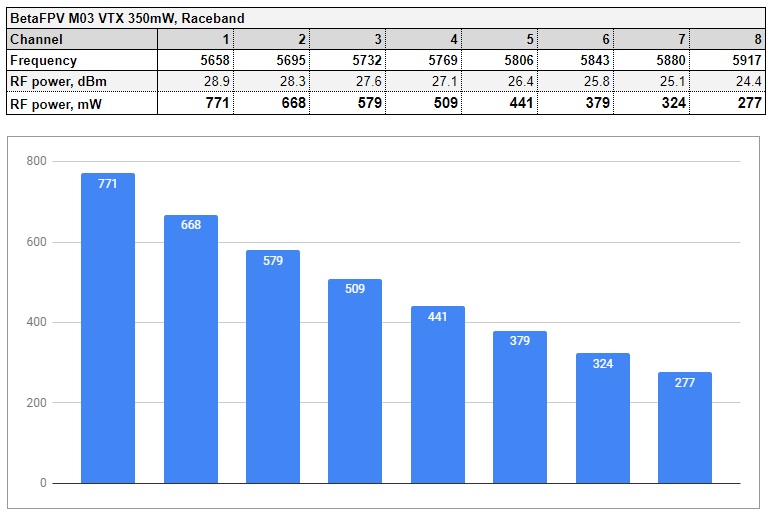
The deviations are really significant. On the 25mW power output you can get the 62mW on the CH1 and the 25mW on the CH8. On the?350mW? power output level you can expect the M03 VTX to output even?770mW of the RF power on the?CH1. and only 277mW on the CH8. The power output of this little VTX is really impressive!
Changing the VTX settings
BetaFPV M03 VTX settings (band, channel and power output level) can be changed by Betaflight OSD control. There is no way how to change the band and the channel manually and You can only change the power output level by pressing the button.
VTX has one multicolor LED indicator for power level display. Green light is for 25mW, Yellow for 100mW, Red for 200mW and Purple light indicates 350mW.
Betaflight setup and VTX Tables
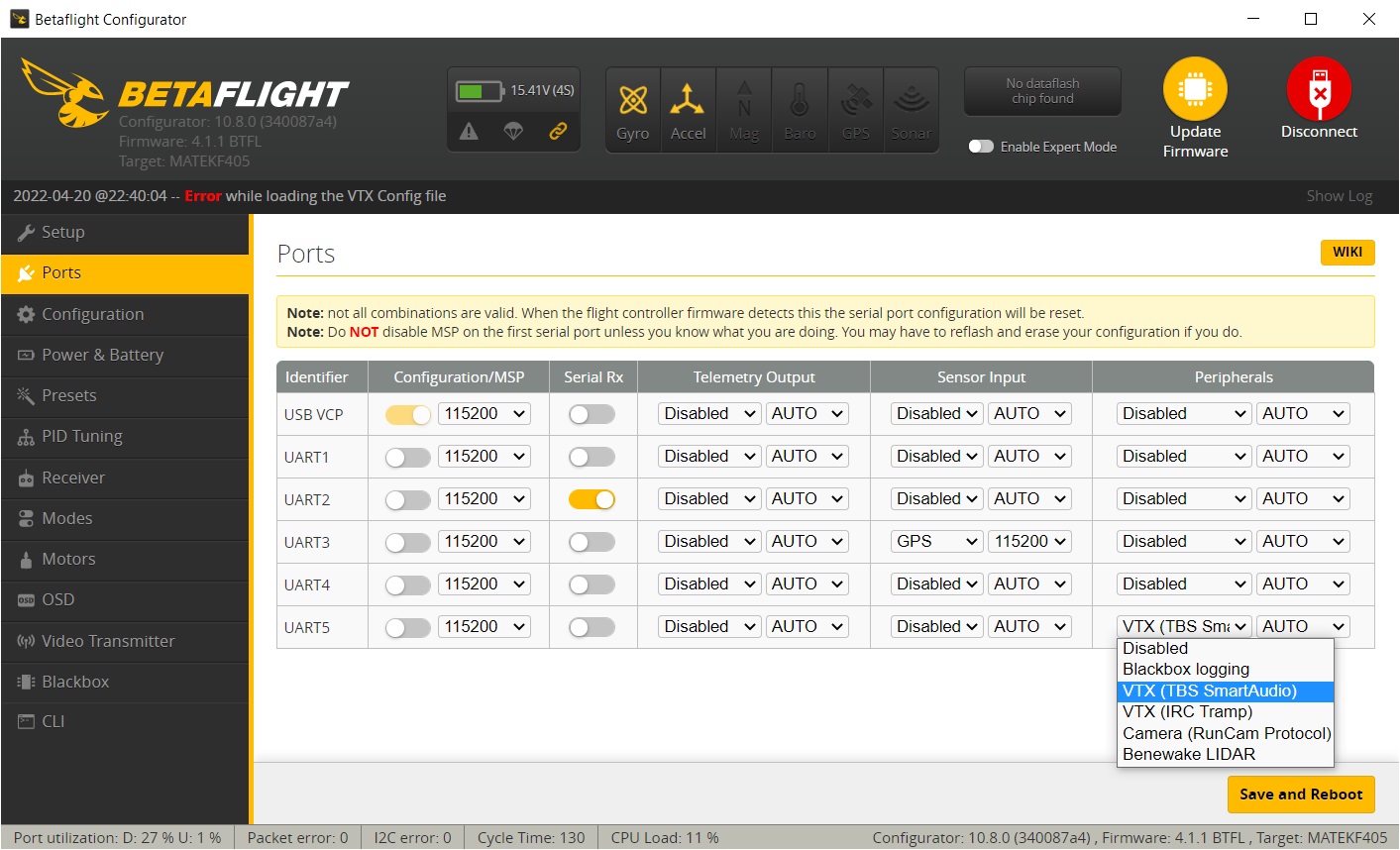
BetaFPV M03 VTX is working with TBS SmartAudio protocol. You should connect the SmartAudio wire from the VTX to the any available TX pad on the FC.
In the Betaflight Configurator, choose TBS SmartAudio protocol in the Peripherals tab
Read more about SmartAudio here:?Guide: SmartAudio VTX control and how to set it up
If you are using (or planning to use) the Betaflight versions 4.x? and want to control the VTX by Betaflight OSD, then you should set up the VTX Tables.
Read more on setting up the VTX tables here:?VTX Tables and how to set them up
Open Betaflight Configurator, connect to the flight controller, select “Video Transmitter” tab. Load the VTX table from the file by clicking on the [Load from file] button.
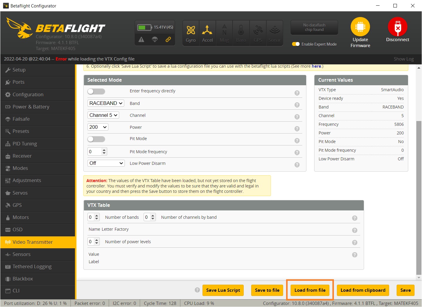
Select the VTX table file. There can be separate VTX table files for?US?and?EU?region as there are different range of the allowed frequencies to use. (Hint: European table has only the?3 channels?on?Raceband).
Once VTX file is loaded, you should see the VTX table with the right frequencies and power settings.
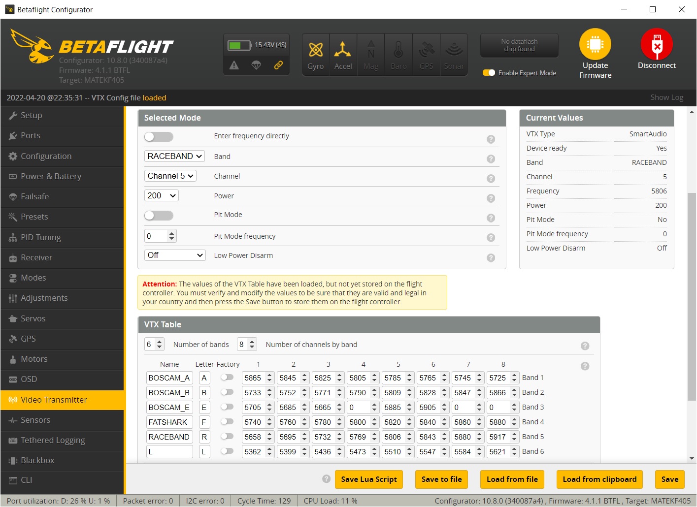
Don’t forget to hit the [Save] button.
BetaFPV M03 VTX Betaflight VTXtable file:?https://drive.google.com/file/d/1qqowepTWmj_be-WsJ-jtUsAx5_aNsos7/view
Conclusions & final thoughts
BetaFPV M03 VTX is the smallest VTX from BetaFPV. Despite being so small it is really powerful as it can output 350mW and even more. I have recorded the power output up to 771mW on the Raceband, CH1. Power output ranges from 62?mW?to?25 mW?on the 25mW power setting and from?771 mW?to?277 mW?on the 350mW setting. On the lower channels you can get enormous amount of the power output. Have that in mind if you are looking for the maximum FPV range.
BetaFPV M03 VTX has probably the best power to weight ratio in the market. It has 401mW/1g ratio. Currently unmatched. It also set my personal record of the nano sized VTX absolute maximum power reached – 771mW.
The bottom line – M03 VTX is definitely one of the best VTX options for whoops and ultralight quadcopters.
BetaFPV M03 VTX is available @
BetaFPV: https://betafpv.com/products/m03-25-350mw-5-8g-vtx
Disclaimer: This item was supplied by BetaFPV for a fair and unbiased review. BetaFPV never asked for a positive review and never influenced my opinion in any way. I’m trying my best to stay uninfluenced and give only my own opinion. All affiliate links if there are any help me purchase items for future reviews and tests.
]]>
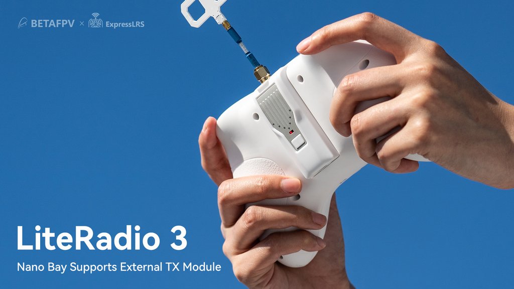
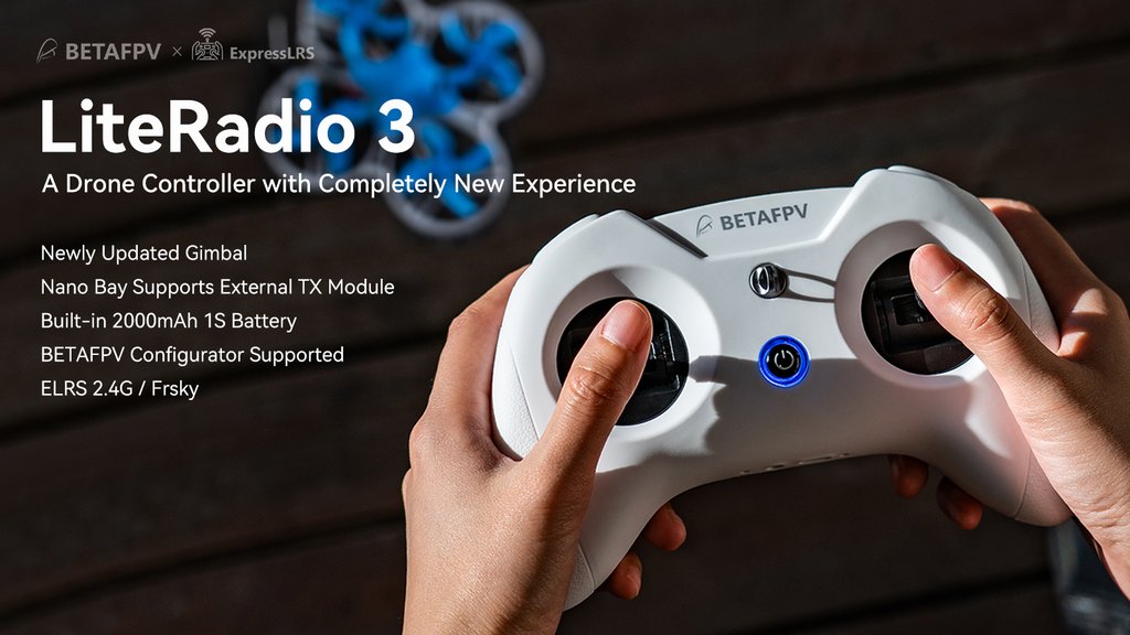
In comparison with LiteRadio 2 SE, the LiteRadio 3 is equipped with a 2000mAh 1S battery, allowing up to 15 working hours (without an external module). A Nano (JR lite) bay on the backside of the radio supports an external module (like?ELRS Nano TX Module) with CRSF protocol. Also LiteRadio 3?gimbal?is newly updated with an accurate potentiometer and adjustable stick ends.
| Comparison table | LiteRadio 3 Transmitter | LiteRadio 2 SE Transmitter |
| Built-in Battery | 2000mAh 1S Battery | 1000mAh 1S Battery |
| Gimbal | Newest durable and accurate?gimbal | Orders from?Dec. are the same as LiteRadio3 |
| Lanyard Hook | Support | Not Support |
| BETAFPV Configurator | Support | Orders from Dec. support |
| Nano Bay for External Module | Support | Not Support |

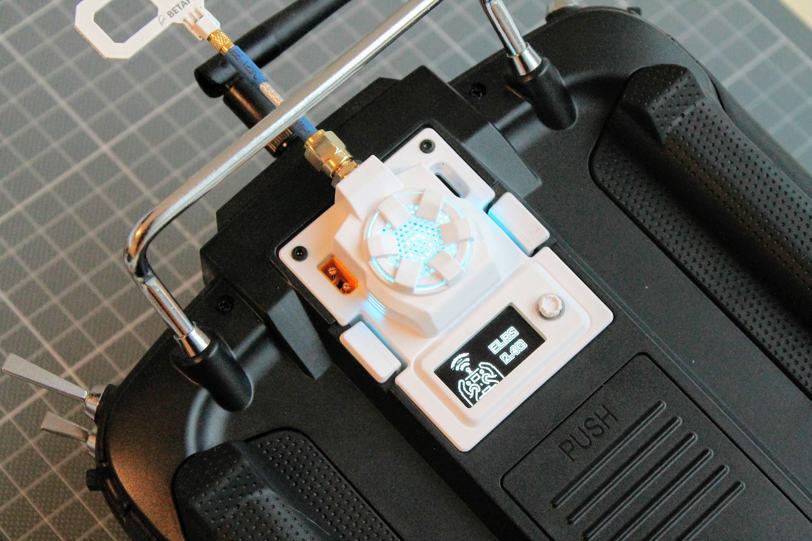
BetaFPV LiteRadio 3 has Nano (JR Lite) external module bay. You can install the external?ELRS (or maybe Crossfire?) TX module in it. Radio uses only CRSF protocol to communicate with the external module.
Available @
BetaFPV:?https://betafpv.com/products/literadio-3-radio-transmitter
LiteRadio 3 Radio Transmitter User Manual:?https://support.betafpv.com/hc/en-us/articles/4412082282009-Manual-for-LiteRadio-3
Specifications:
Item: LiteRadio 3 Radio Transmitter
Frequency: 2.4GHz
2.4GHz System: CC2500/SX1280
Channel: 8
Support Protocol: Futaba S-FHSS/Frsky FCC D16/Frsky LBT D16/Frsky D8, ExpressLRS 2.4G
Power: ELRS version 25mW/50mW/100mW, Frsky version 100mW
Adapted Drone Type: Multirotor, Airplane
Support USB Charging / Firmware Update
Support BETAFPV Configurator / Most Practice Simulator
LED Light: Green-Power On / Red-Warning if the voltage is lower than 3.5V / Blue-Normal
Battery: Built-in 2000mAh 1S Battery
Charging Connector: USB?Type-C
Recommend External TX Module: ELRS Nano TX Module
Recommend Accessories: Nano Gimbal for LiteRadio 3, Storage Case, Transmitter Neck Strap

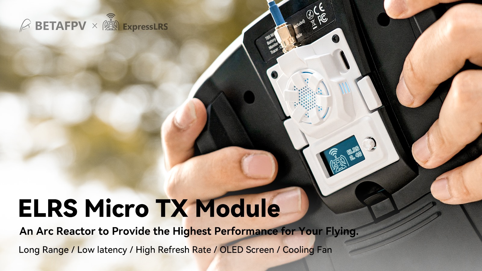
Lets take a close look at this interesting ELRS Module.
Specifications
BetaFPV ExpressLRS Micro TX transmitter
Available @ BetaFPV: https://betafpv.com/products/elrs-micro-tx-module
Banggood:?https://www.banggood.com/BETAFPV-ExpressLRS-ELRS-…-Micro-TX-Module-…-1912251.html
Packet refresh rate: 25Hz/50Hz/100Hz/200Hz (915MHz/868MHz), 50Hz/150Hz/250Hz/500Hz (2.4GHz)
RF output power: 25mW/50mW/100mW/250mW/500mW (2.4GHz), 100mW/250mW/500mW (915MHz/868MHz)
Frequency bands (Micro RF Module 2.4G version): 2.4GHz ISM
Frequency bands (Micro RF Module 915MHz/868MHz version): 915MHz FCC/868MHz EU
Input voltage: 5V~12V
XT30 port: 5V~12V, recommend 2S (8.4V) battery, DO NOT support 3S (12.6V) or above
USB port: Type-C
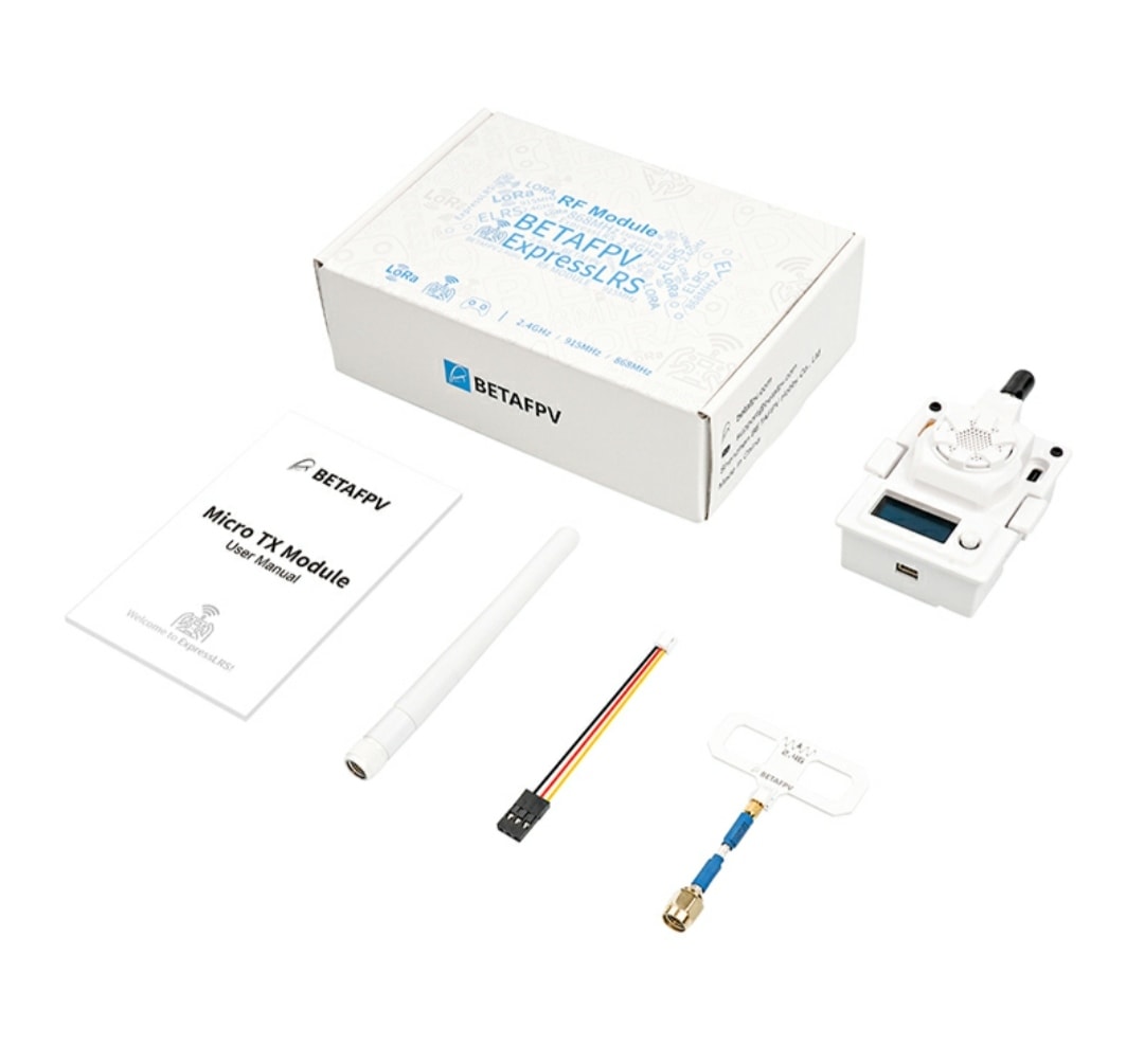
Package contents
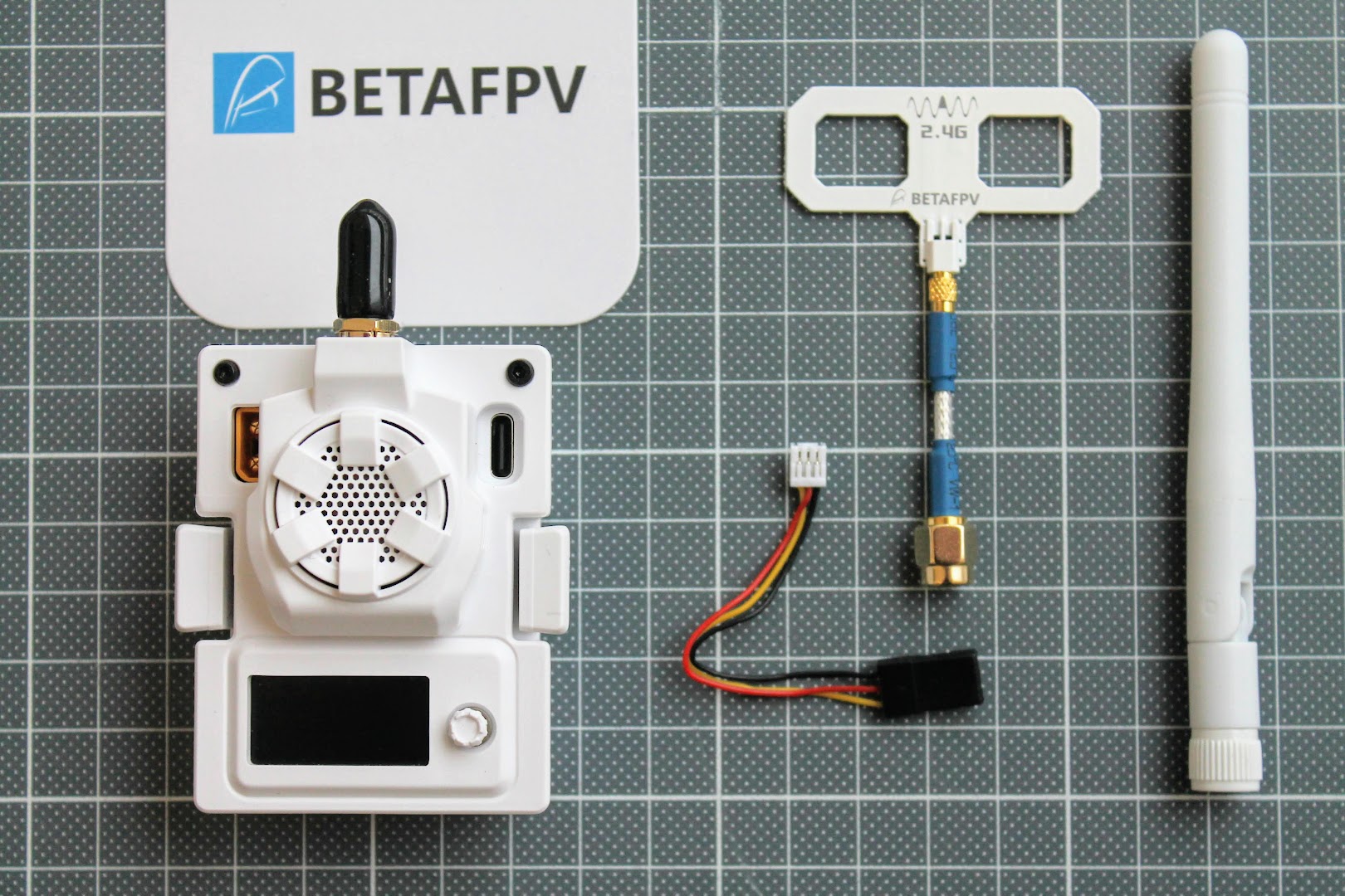
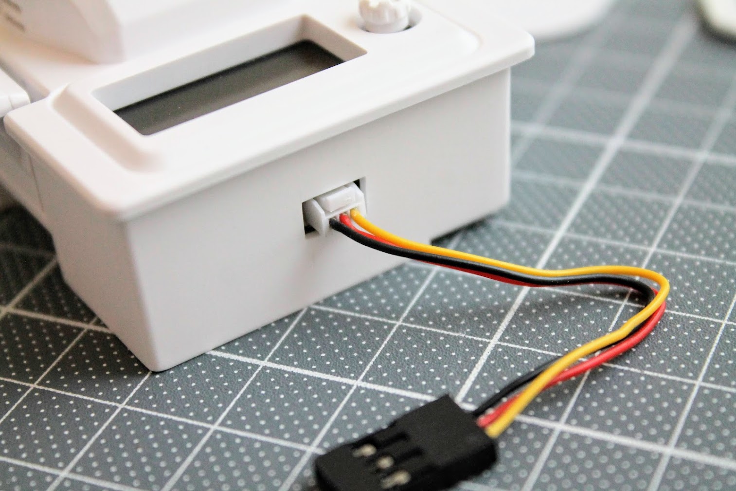
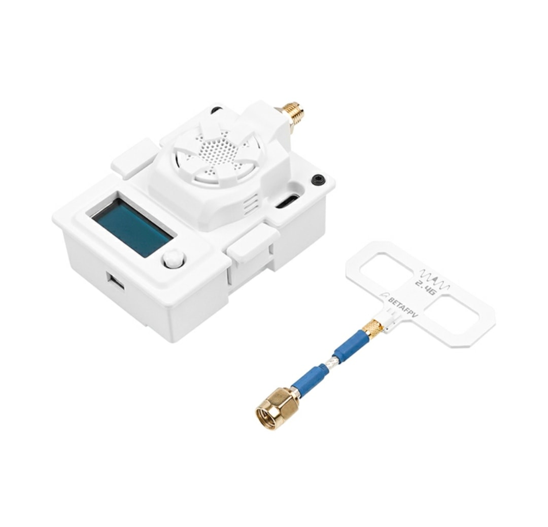
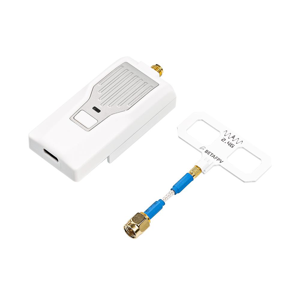
BetaFPV ExpressLRS Micro TX module comes with two antennas – linear whip style dipole antenna and Moxon type antenna. You also get 3-pin connector cable for connecting the module to radio transmitter.
Closer look
There is a JST-GH 1.25mm 3pin connector socket on the bottom side of the Micro TX module. It can be used for connecting the module with the radios that don’t have the JR module bay (but support CRSF protocol to communicate with the TX module)
BetaFPV Micro TX Module can be powered by external power supply (5V~12V) for providing the supplement power especially on the higher RF power output levels (250mW-500mW)
Max allowed input voltage is 12V. DO NOT use 3S or above battery?to power up the TX module via XT30 port. Otherwise, the power supply chip in the TX module will be damaged permanently.
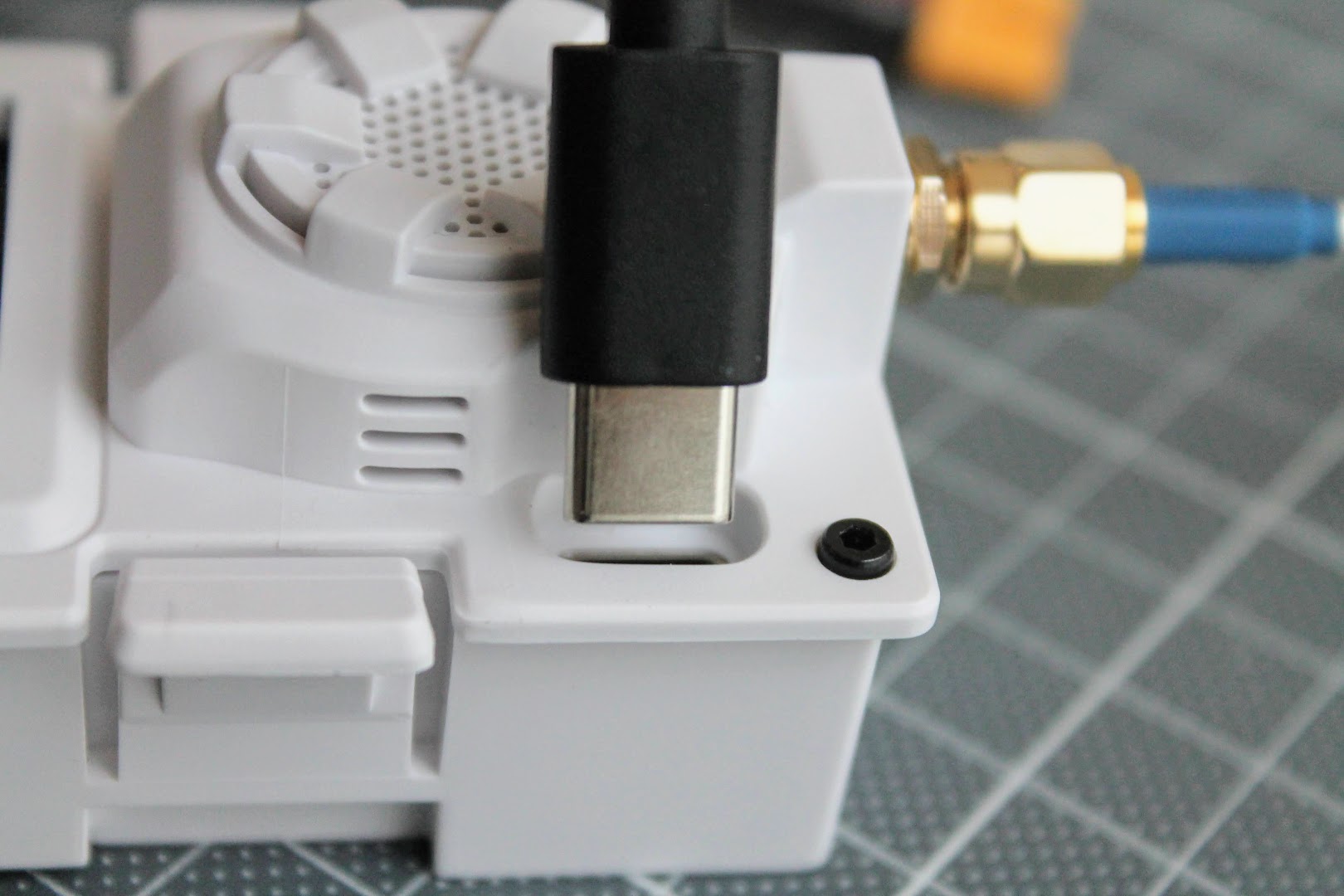
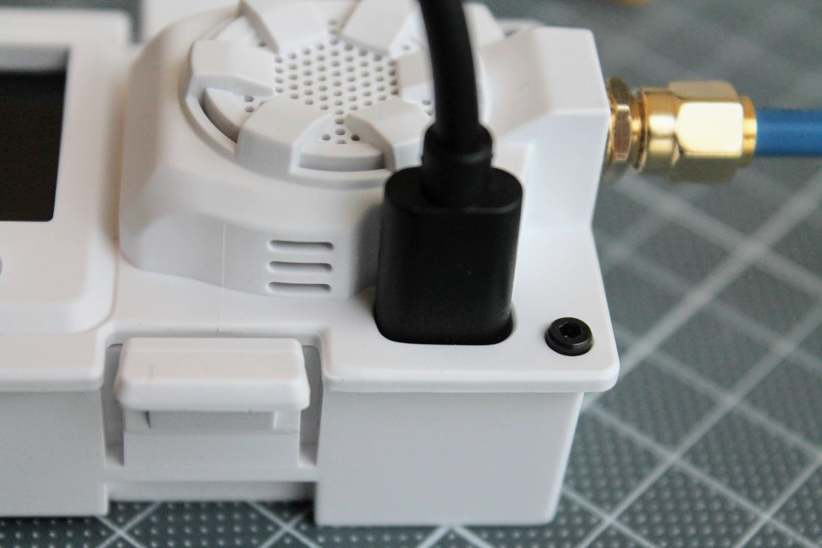
On the top right side of the module you can find the USB Type-C connector slot for connecting the module to the computer and updating the firmware. Read the notes about the USB cable compatibility below.
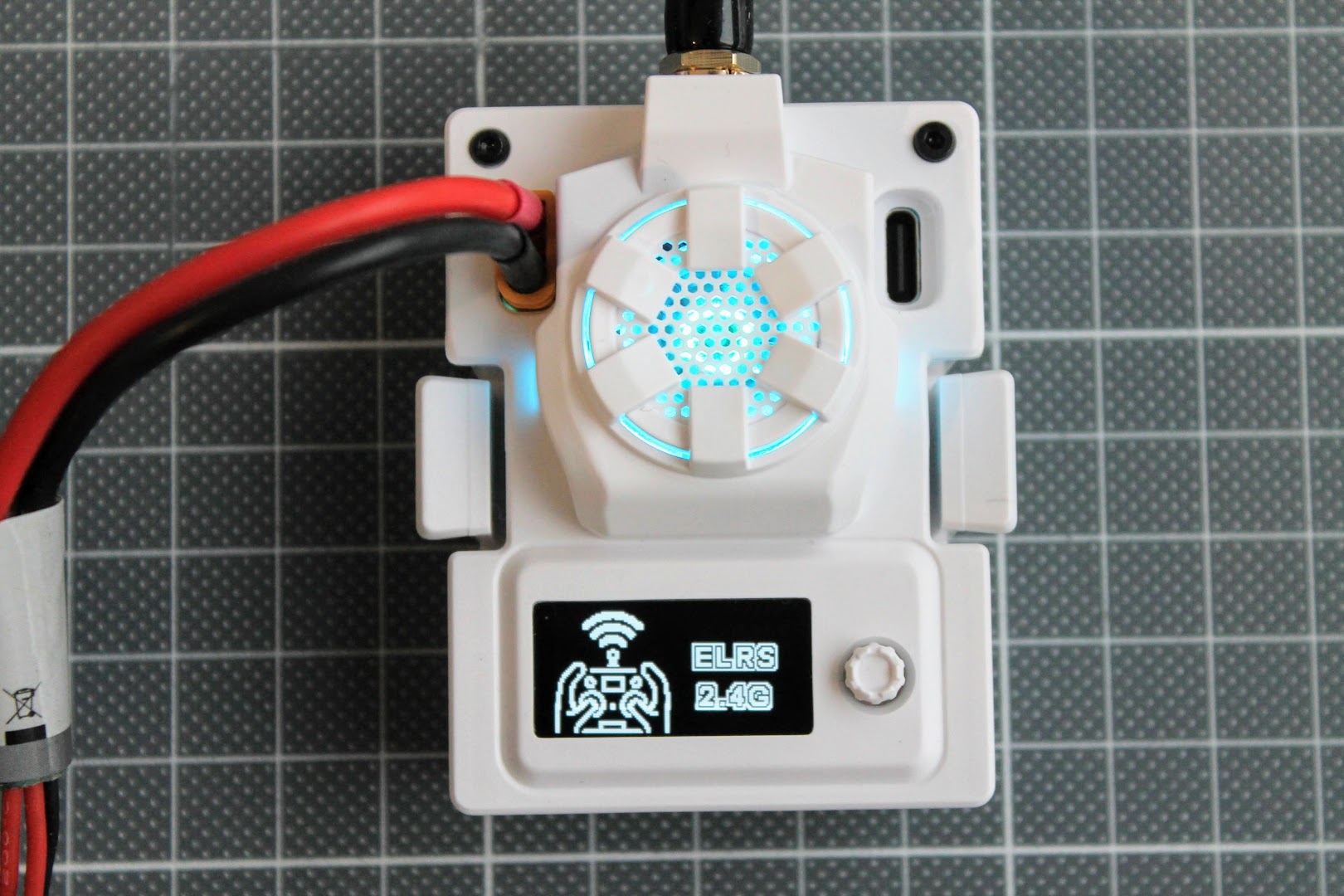
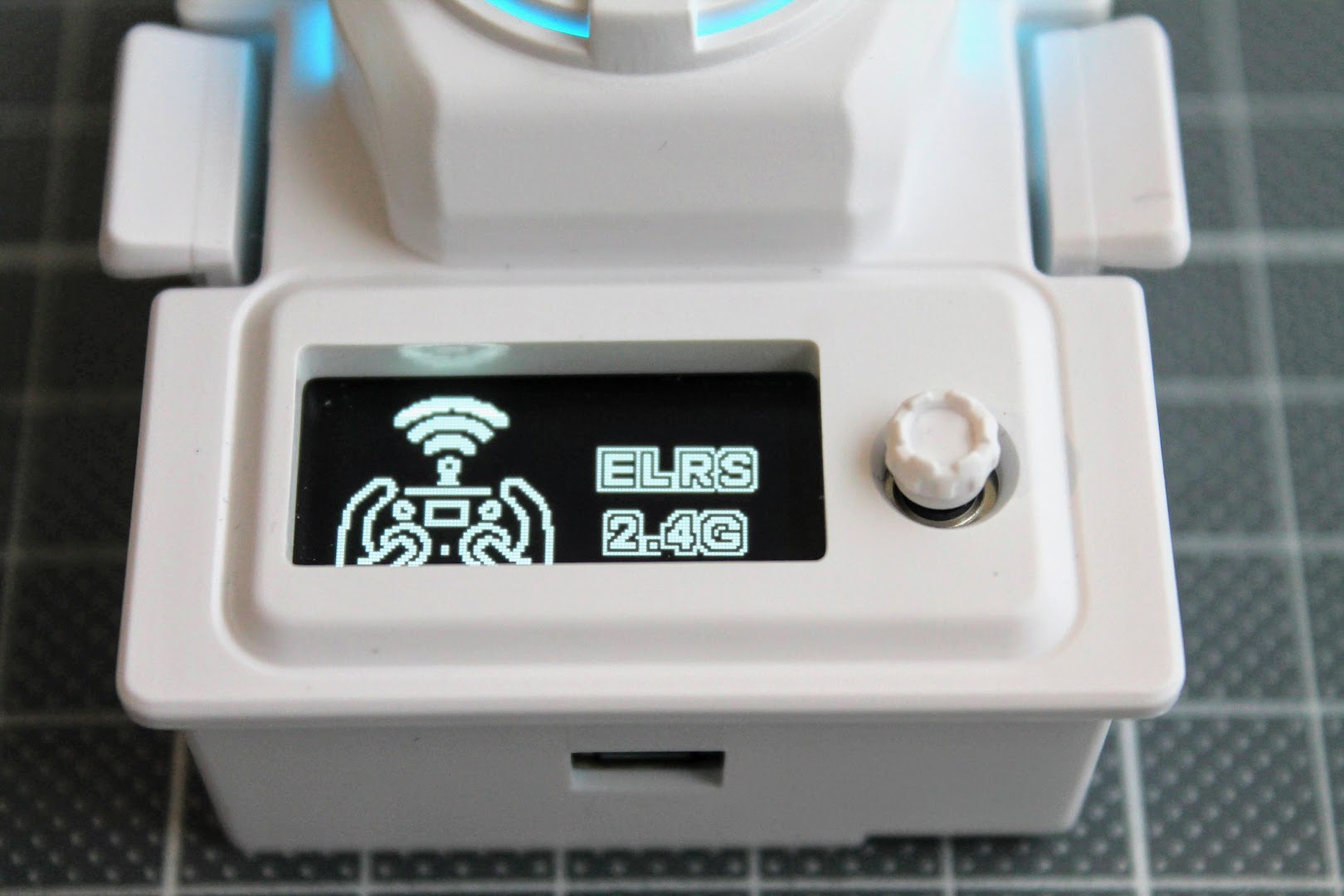
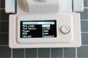
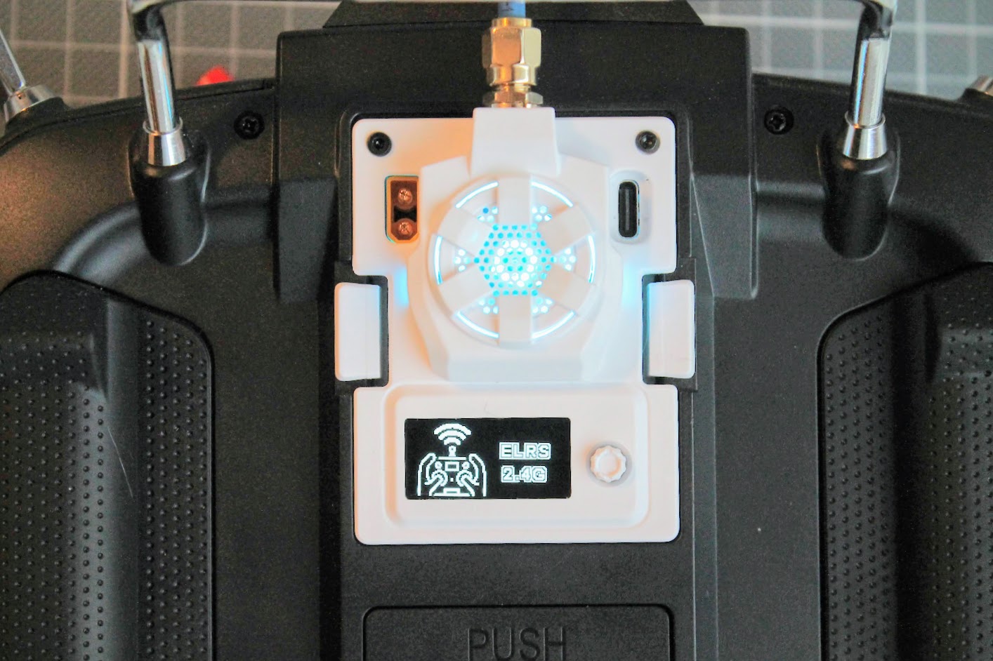
BetaFPV Micro TX has OLED screen and the 5-way joystick for navigation through the ELRS module settings. OLED screen shows the ELRS logo screen and the settings page is “locked”. you need to long press the joystick to “unlock” the settings.
 |
 |
The BetaFPV MicroTX module can be powered by JR bay or can be powered by external power source and be used with ANY radio transmitter that supports CRSF protocol. Examples of such radios: TBS Mambo, Futaba T18SZ, Futaba?T16SZ,?Flysky NV14 and others.
 |
|
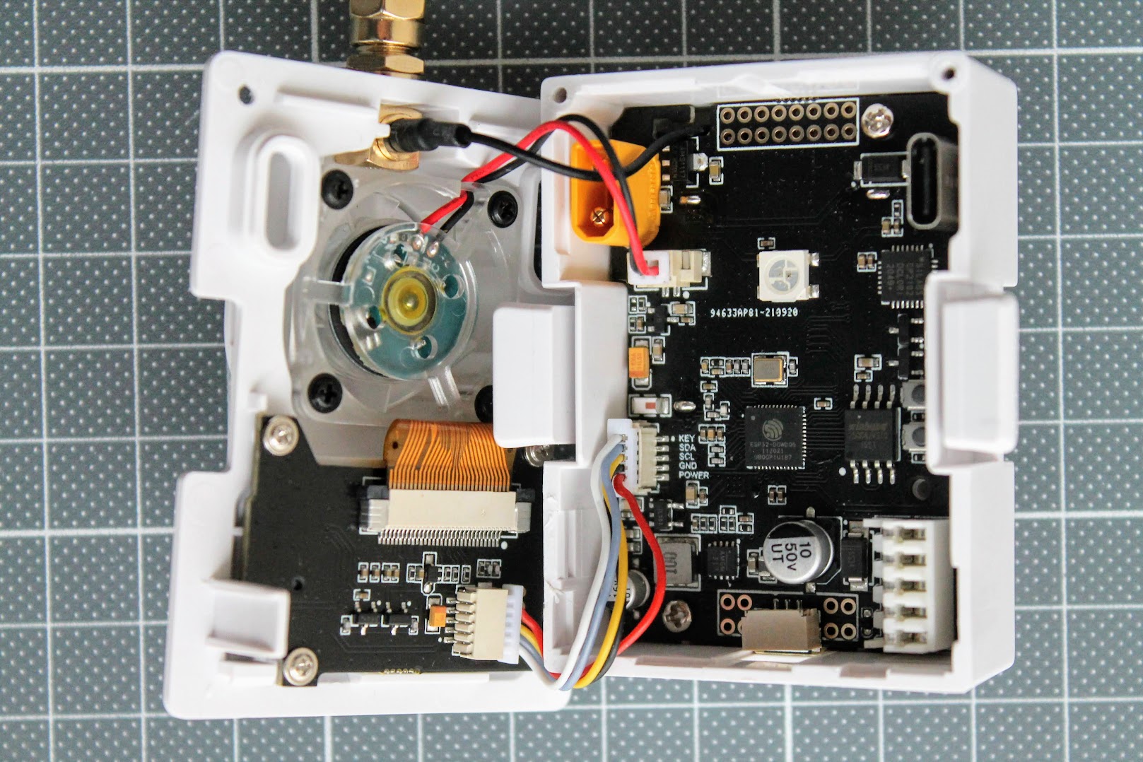
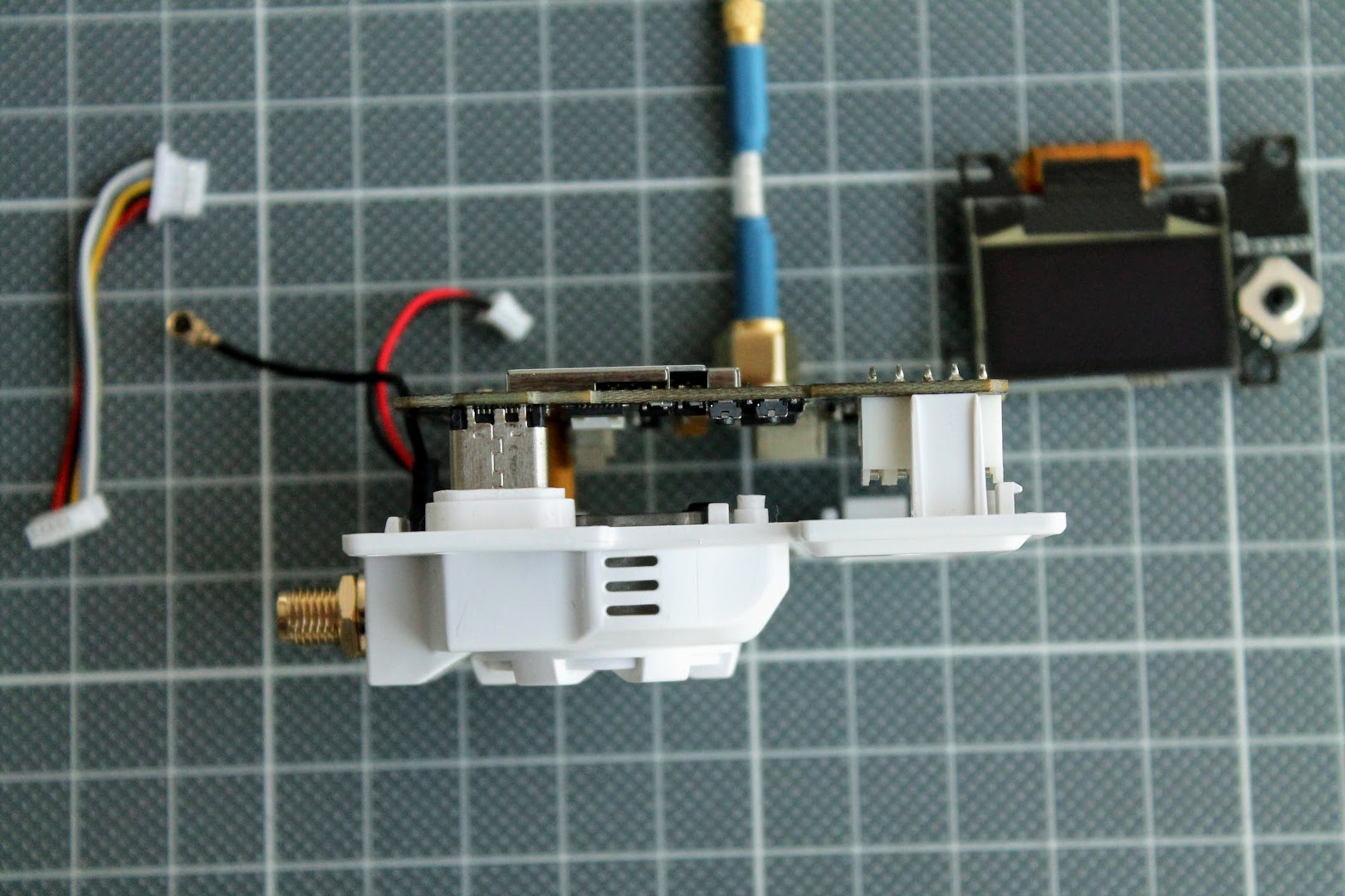
Inside the module
Inside the module you can find the main PCB, cooling fan, antenna pigtail and the daughter board with OLED screen and 5-way joystick.
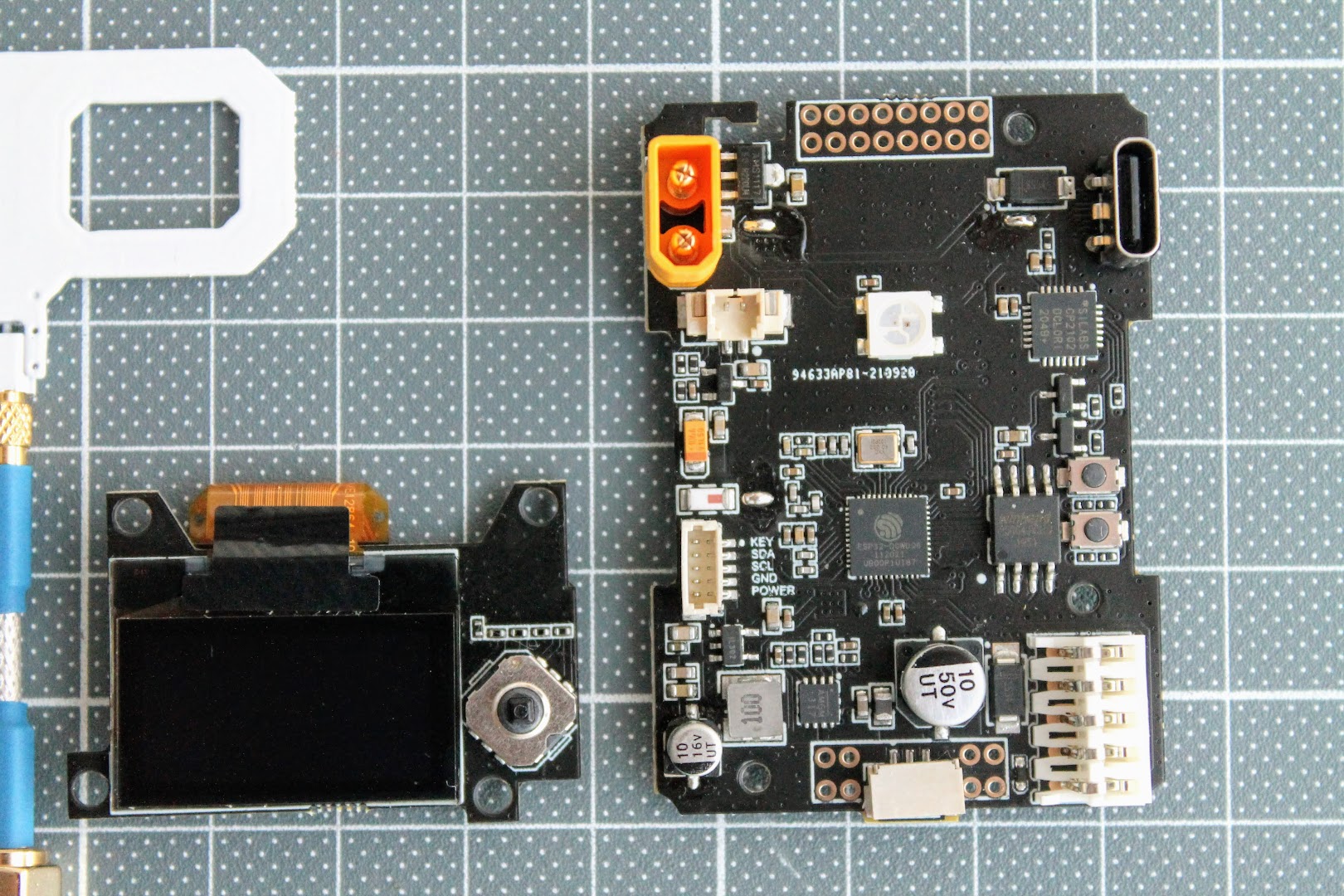
The top and the bottom views of the module PCB.
 |
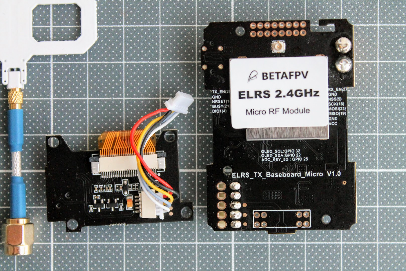 |
There is a RGB LED in the middle of the module on the top side and the RF part is located on the bottom of the board.
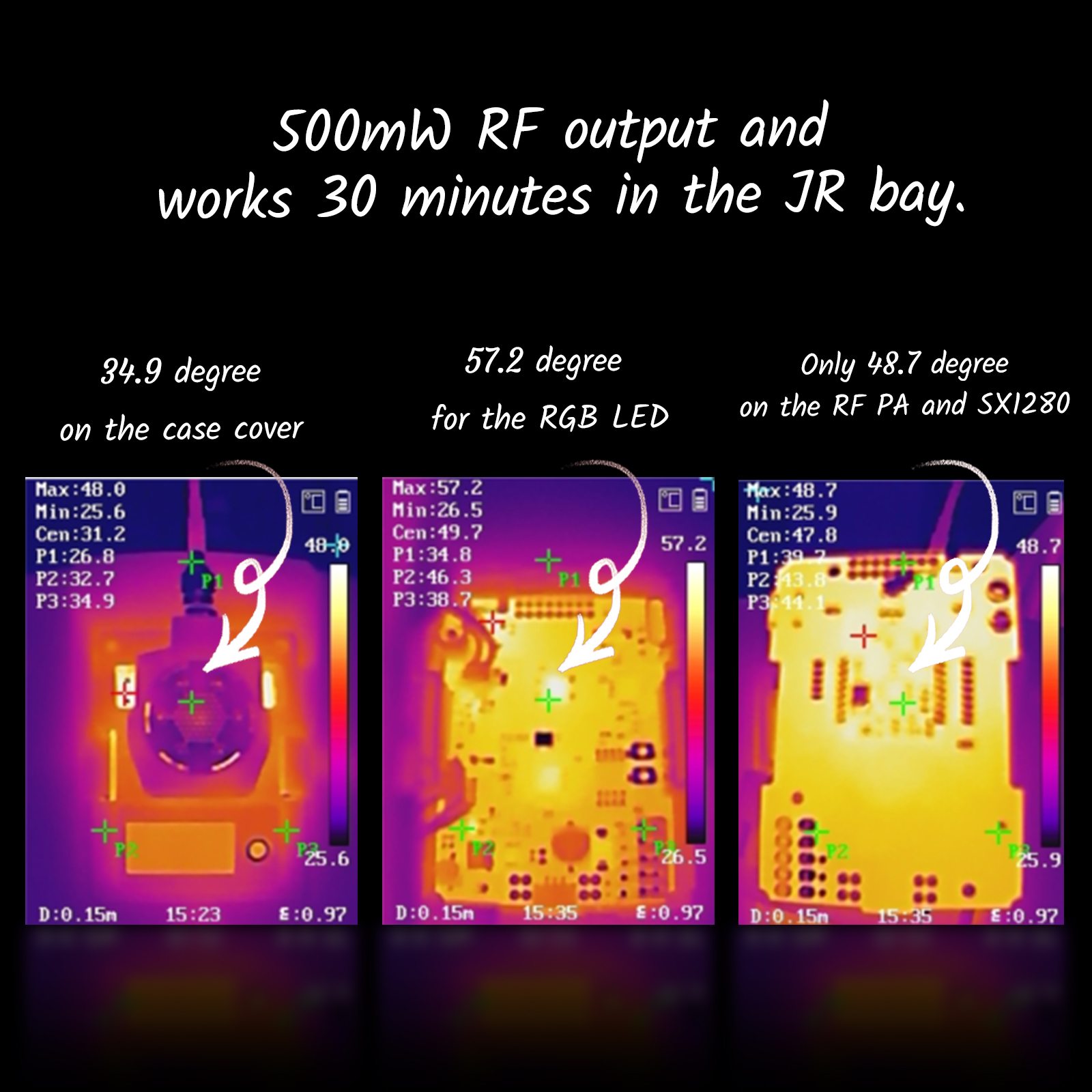
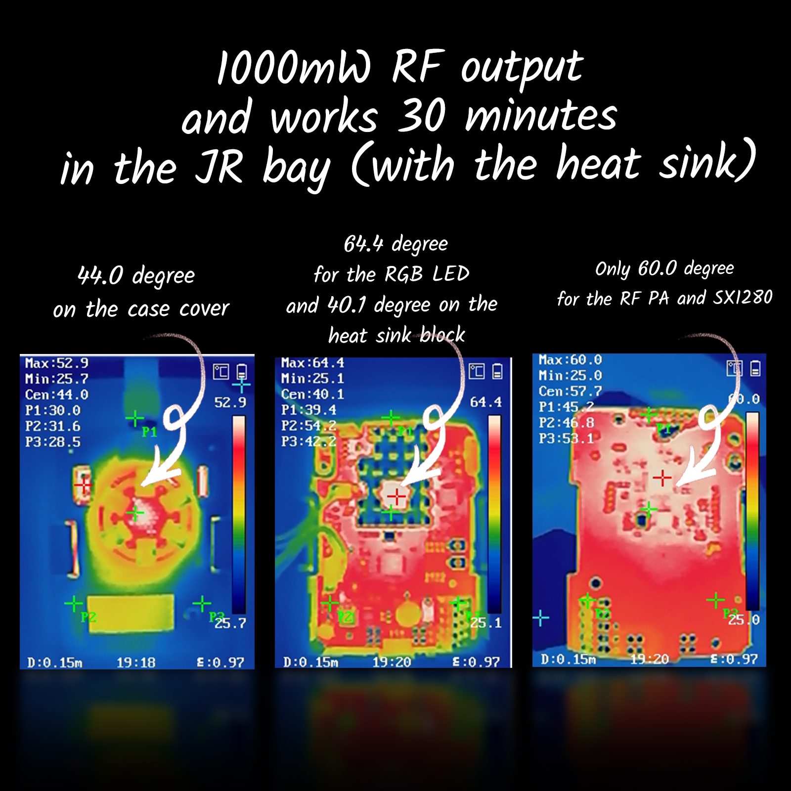
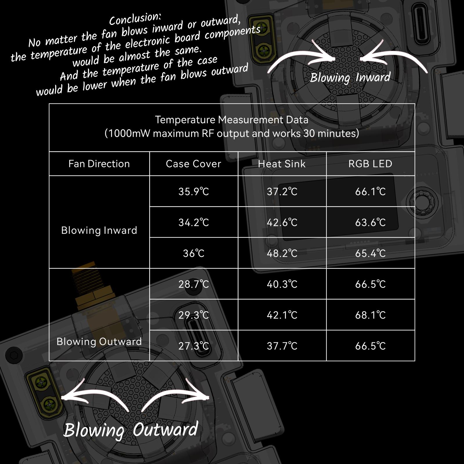
There is a lot of space inside the module for air to circulate and keep the module cool. RF power output test show that this module does not overheat and power output does not degrade on heating up.
RF power output measurements
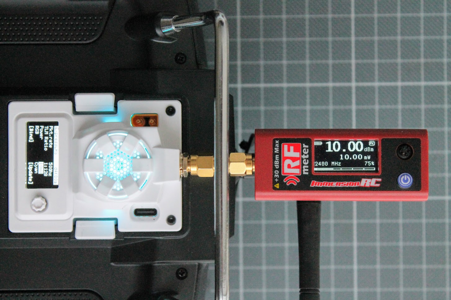
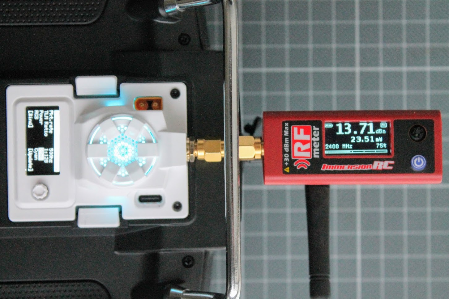
I have tested the power output with ImmersionRC RF Power meter on 10mW, 25mW, 100mW, 250mW and 500mW settings.
10mW
25mW
50mW
100mW
250mW 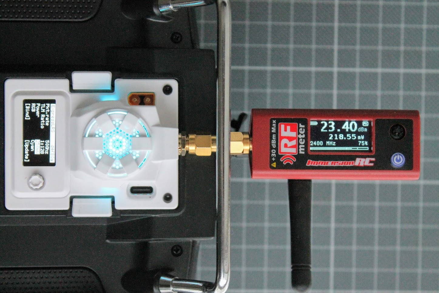
500mW 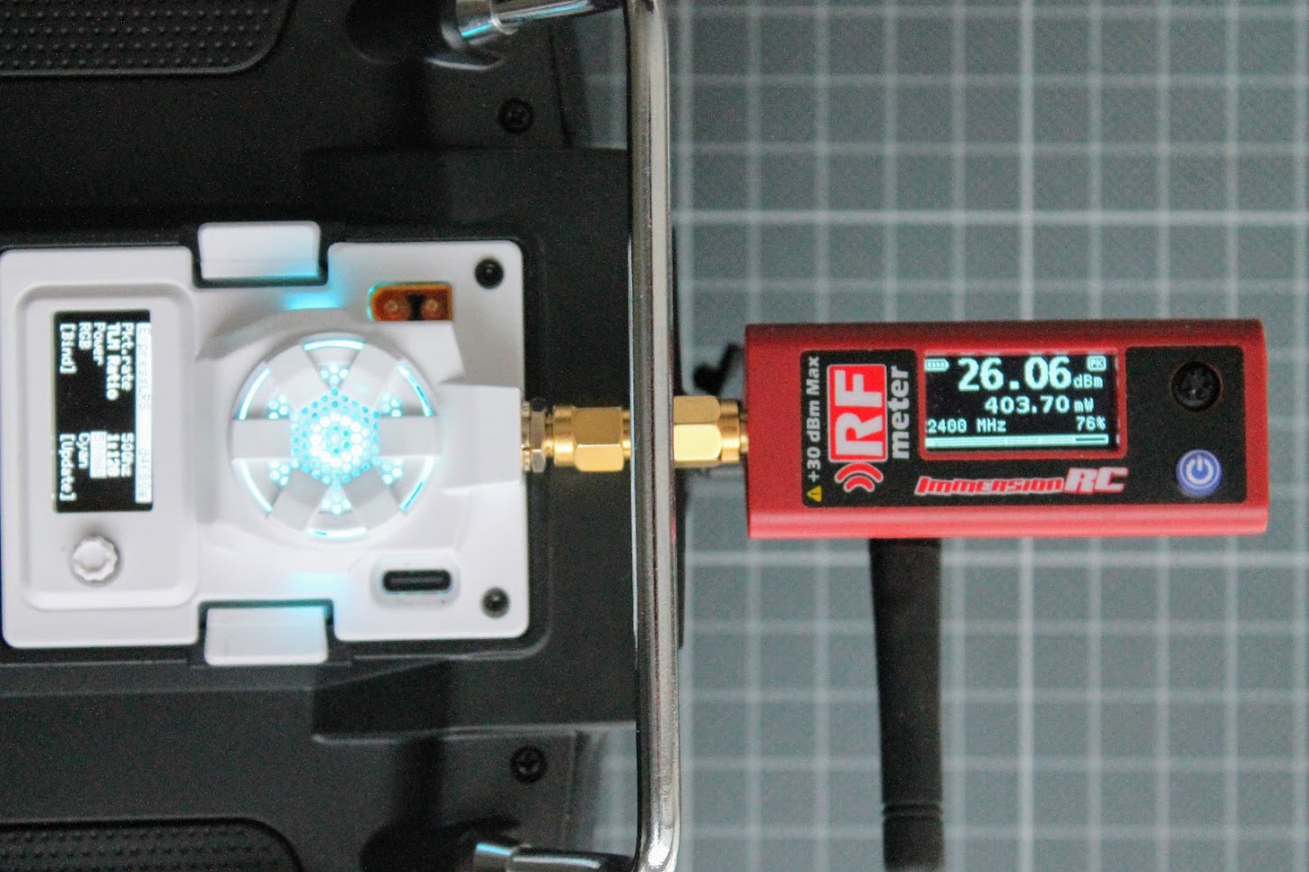
500mW after 30min of runtime.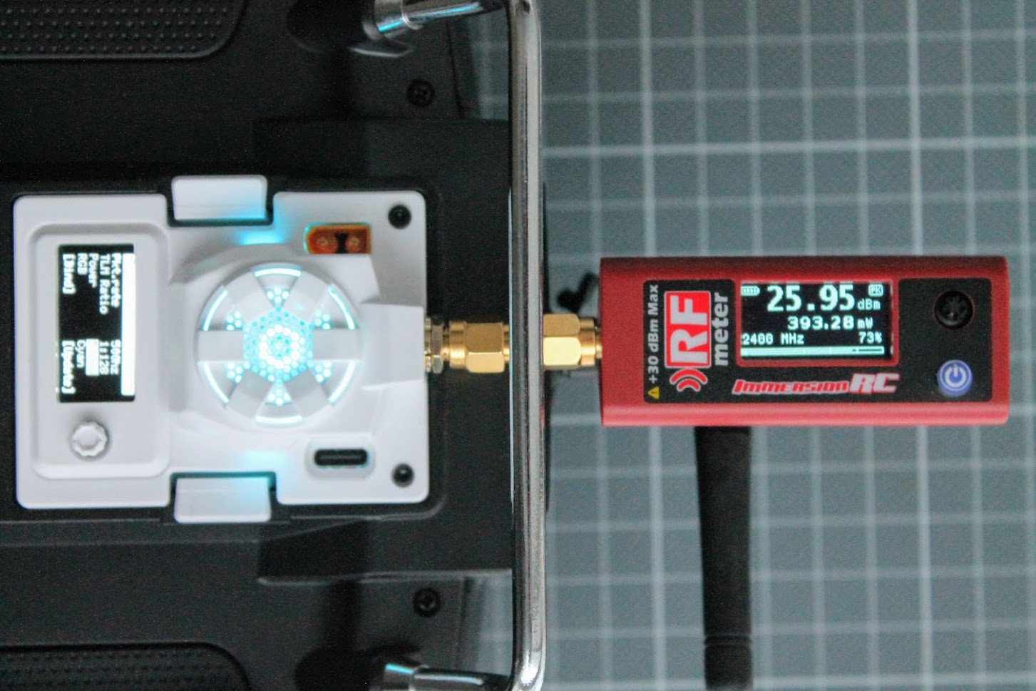
Known issues
There are several known issues so far. BetaFPV has faced them, provided the feedback and is taking actions to fix them. Some of that issues are already fixed or at least explained in detail below.
Link is lost when entering the BetaFPV OLED menu
The moment when you enter the BetaFPV Micro TX OLED menu by long pressing the joystick button, RC link with the receiver is lost and this can lead to your aircraft to failsafe.?It is expected to be fixed in the official ELRS version 2.1.?Meanwhile there is an unofficial BetaFPV firmware with this issue fixed. Look for the “How to update (unofficial) ELRS firmware?” section below.
OLED screen is not supported in the ExpressLRS
The Micro TX module comes with the custom BetaFPV firmware and it’s OLED screen is not supported in the official ExpressLRS firmware for now. It is expected to be supported in the official ELRS version 2.1. Meanwhile there is an unofficial BetaFPV firmware with OLED support. Look for the “How to update (unofficial) ELRS firmware?” section below.
5-way joystick is working as simple button and not a joystick
5-way joystick for navigation is working as simple button. No up-down, left-right positions work. If you want to move through the menu, you need to long press the joystick like a button.
It is expected that the 5-way joystick? be supported in the official ELRS version 2.1. Meanwhile there is an unofficial BetaFPV firmware with full 5-way joystick support. Look for the “How to update (unofficial) ELRS firmware?” section below.
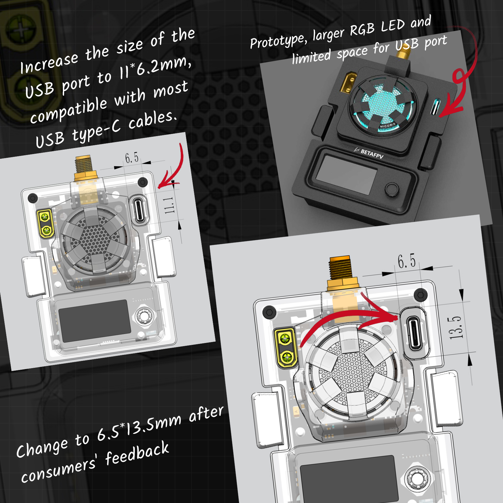
USB Type-C port too small
The USB port housing on the TX module is 6.2*11mm and may not fit with all the USB cables your own. A spare USB data cable (Type-A to Type-C) is included in the package for all order since November 18.
|
 |
BetaFPV response to the USB Type-C connector port being too small
 |
 |
 |
RF Chip on the back side of the module
Some users made a concern that RF chip is populated on the back side of the TX module PCB and can not be cooled properly.
|
|
BetaFPV response about RF module being on the back side and crystal capacitors:
 |
 |
 |
How to update (unofficial) ELRS firmware?
Until the BetaFPV Micro TX is supported by official ExpressLRS branch, you need to download the source code of master-betafpv-oled-menu branch to local disk from BetaFPV Github?(https://github.com/BETAFPV/ExpressLRS).
Press the button [Code] and select the “Download ZIP“.
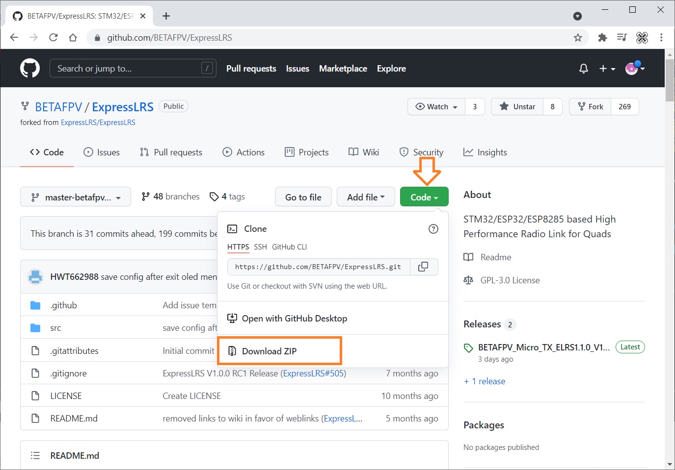
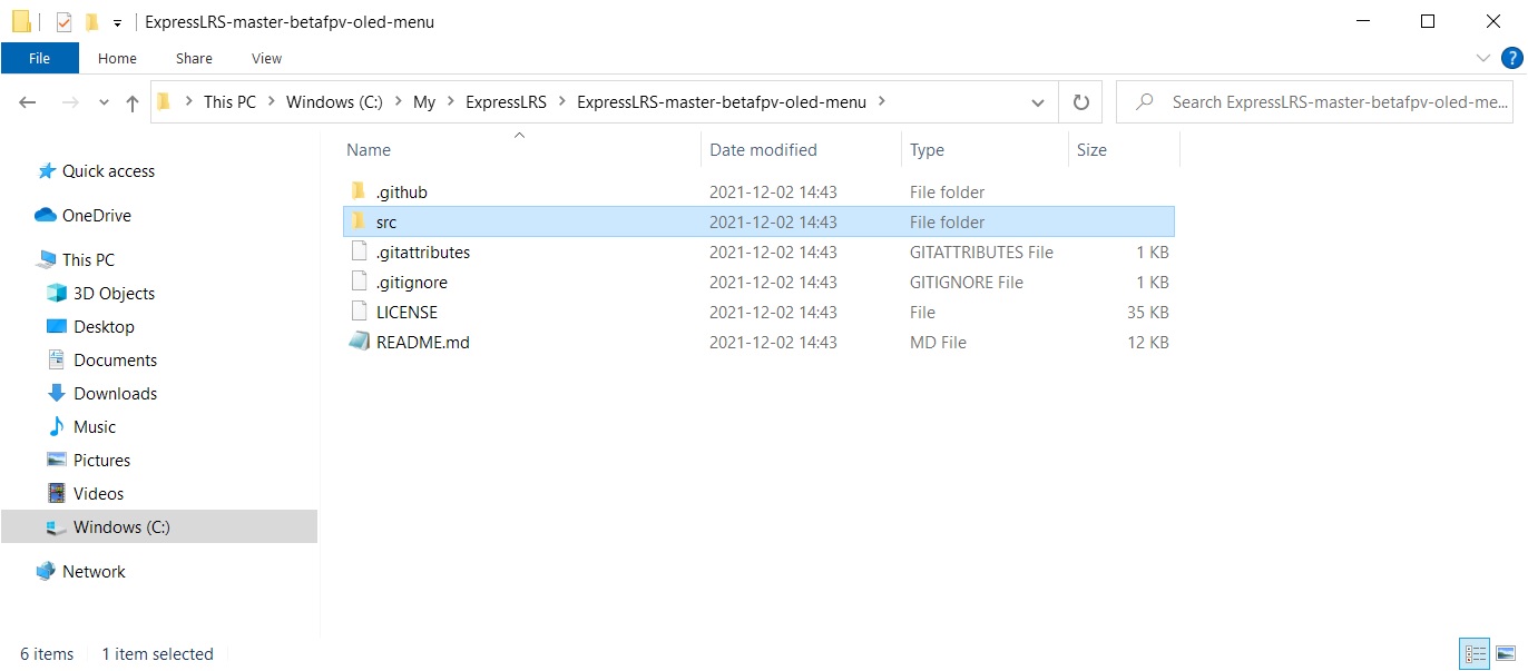
Unzip the downloaded source code to some local folder.
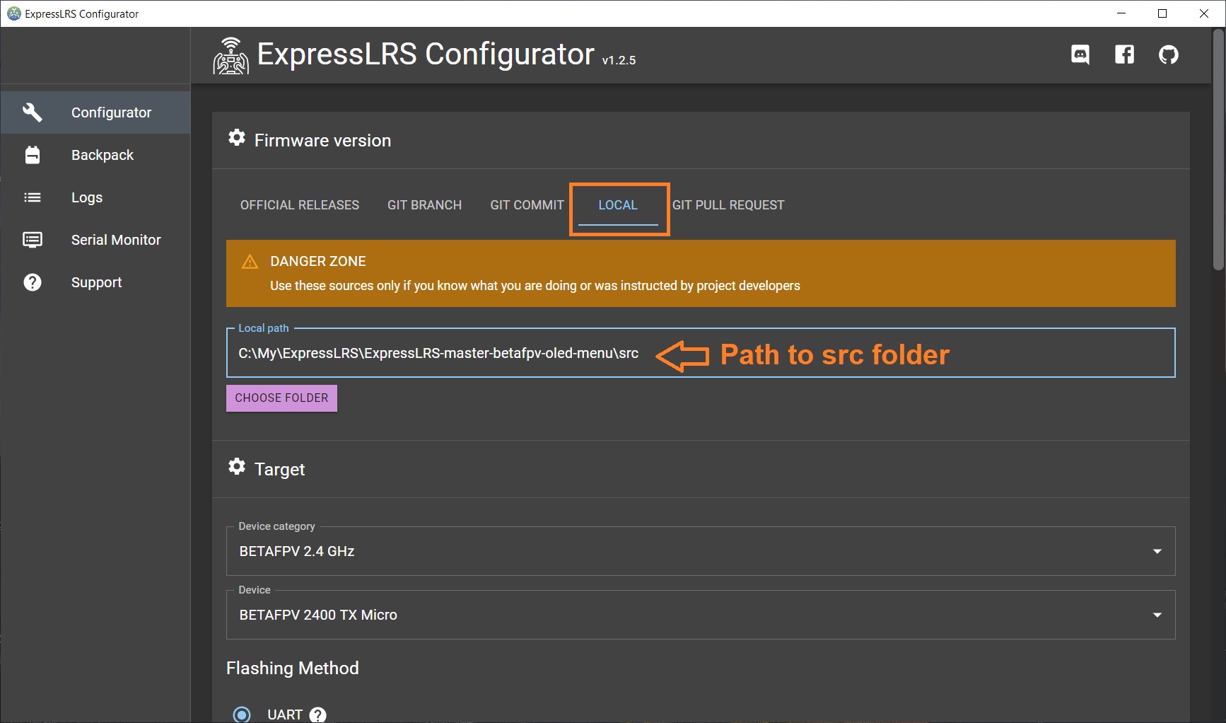
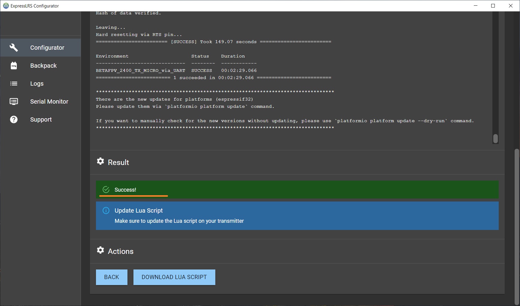
Open the ExpressLRS Configurator and select the [Local] tab and then navigate to the \src\ folder? in “Local path setting” . Select the target device “BETAFPV 900/2400 TX Micro”. From that point, you can setup your own binding phrase and other options as usual flashing method. Read more on updating the ExpressLRS firmware here:?ExpressLRS – Complete Guide.
Press [BUILD & FLASH]
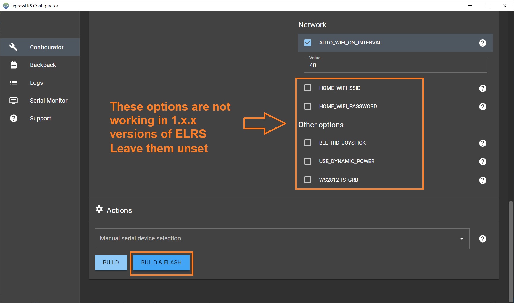
And wait for the module to be flashed successfully.
Conclusions
BetaFPV ELRS Micro TX?module was the first module to introduce the OLED screen and 5-way joystick for navigation. Being first means you are doing something new and most probably mistakes too. This module was no exception. BetaFPV hurried to release this module and made a few mistakes. 5-way joystick was implemented as simple button, entering the module menu failsafed the aircraft. Some USB cables does not fit into the slot and overall module design. These mistakes are fixed now.
Comparing the similar ELRS TX modules with the similar price tag on the market, BetaFPV Micro TX has a few advantages – OLED screen, joystick navigation, up to 500mW RF output, possibility to use on non OpenTX radios.
I do like the possibility to set the settings via joystick and the LUA script. The output power of the 500mW is more than enough for almost any pilot and any aircraft – ELRS can go tens of kilometers on the 100mW.
Once the BetaFPV Micro TX ELRS module is fully supported by the official ExpressLRS code (scheduled for version 2.1), this will be the great choice of ELRS TX module. The only thing I’m missing in this module is ESP backpack feature.
Links
BetaFPV ExpressLRS Micro TX module website:?https://betafpv.com/products/elrs-micro-tx-module
BetaFPV ExpressLRS Micro TX on Banggood:?https://www.banggood.com/BETAFPV-ExpressLRS-…-Micro-TX-Module-…-1912251.html
BetaFPV ExpressLRS Micro TX module User Manual:?https://support.betafpv.com/hc/en-us/article_attachments/4409154931225/Manual_for_Micro_TX_Module.pdf
ExpressLRS guide:?ExpressLRS –? Open Source Long Range radio control system – Complete Guide
BetaFPV branch of the ExpressLRS source code:?https://github.com/BETAFPV/ExpressLRS
Disclaimer: This item was supplied by BetaFPV for a fair and unbiased review. BetaFPV never asked for a positive review and never influenced my opinion in any way. I’m trying my best to stay uninfluenced and give only my own, honest and as much as possible unbiased opinion. All affiliate links, if there are any, help me purchase items for future reviews and tests.
]]>
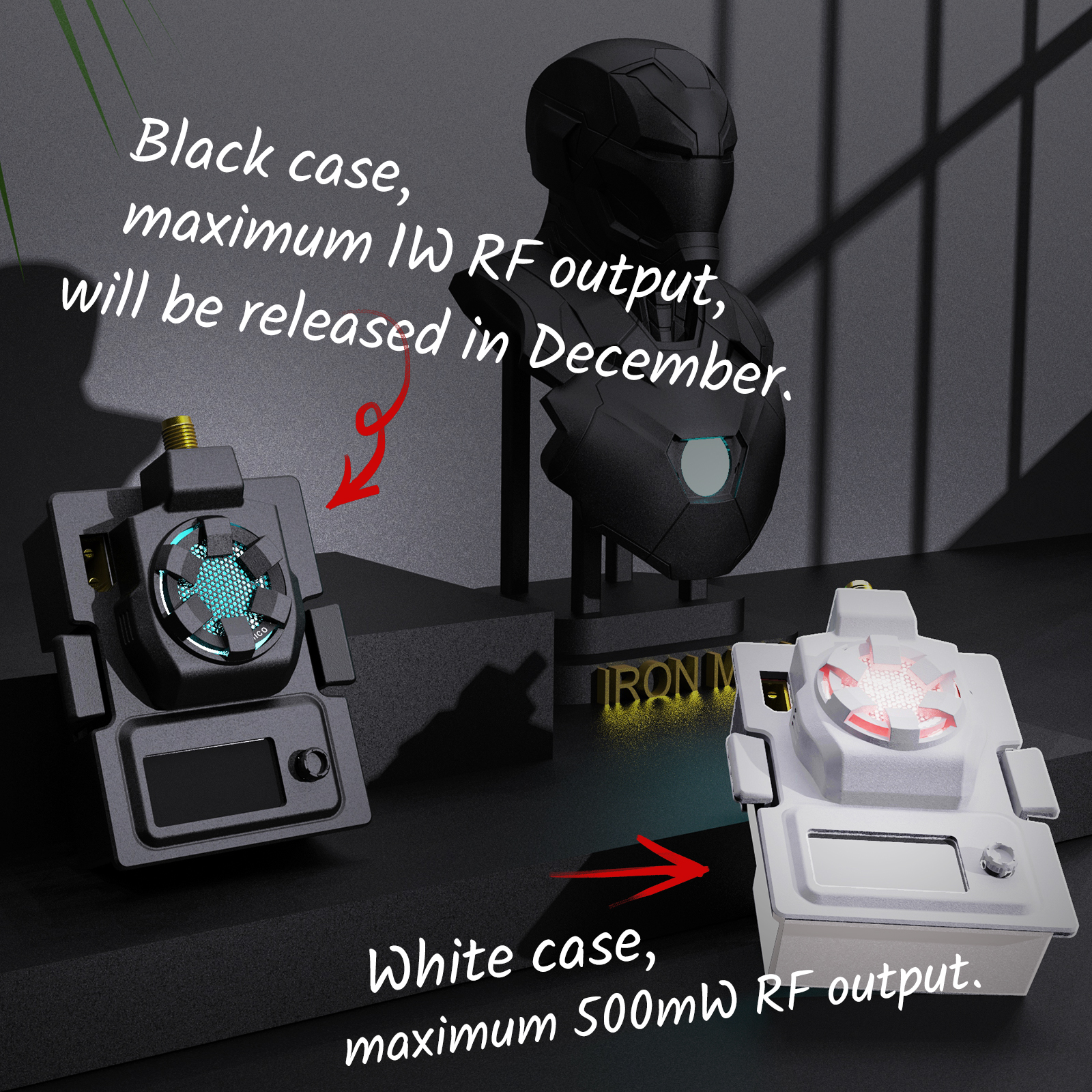
BetaFPV ELRS Micro TX module has output power up to 500mW.??OLED screen and navigation button makes possible to change the ExpressLRS settings without the OpenTX Lua script, enabling the support for the radios that don’t run on OpenTX firmware (Futaba, Radiolink, etc).
There is USB Type-C connector for firmware updates and XT30 connector for external power support.
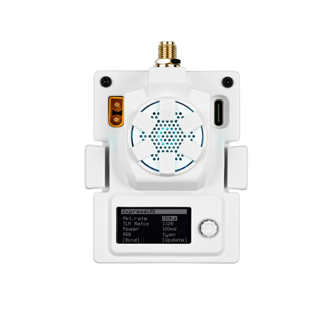
BetaFPV ELRS Micro TX module has cooling fan that turns on automatically according to the output power level (start from 250mW) and? multicolor LED light to ad fancy lighting for on your module.
Oh, and BetaFPV states that this module has “An Arc Reactor to provide the highest performance…”?
Available in 2.4GHz, 868MHz and 915MHz options @
BetaFPV:?https://betafpv.com/products/elrs-micro-tx-module
Specifications
Packet refresh rate: 25Hz/50Hz/100Hz/200Hz (915MHz/868MHz), 50Hz/150Hz/250Hz/500Hz (2.4GHz)
RF output power: 25mW/50mW/100mW/250mW/500mW (2.4GHz), 100mW/250mW/500mW (915MHz/868MHz)
Frequency bands (Micro RF Module 2.4G version): 2.4GHz ISM
Frequency bands (Micro RF Module 915MHz/868MHz version): 915MHz FCC/868MHz EU
Input voltage: 5V~12V
XT30 port: 5V~12V, recommend 2S(8.4V) battery, DO NOT support 3S(12.6V) or above
USB port: Type-C
Lets look what was changed or updated:
BetaFPV Meteor65 ELRS
Meteor65 ELRS has the newest?F4 1S 5A FC and new M03 VTX. Now you have the option to buy the Meteor65 with integrated ExpressLRS receiver and ceramic antenna on board. VTX was upgraded to the whooping 350mW?RF output power.
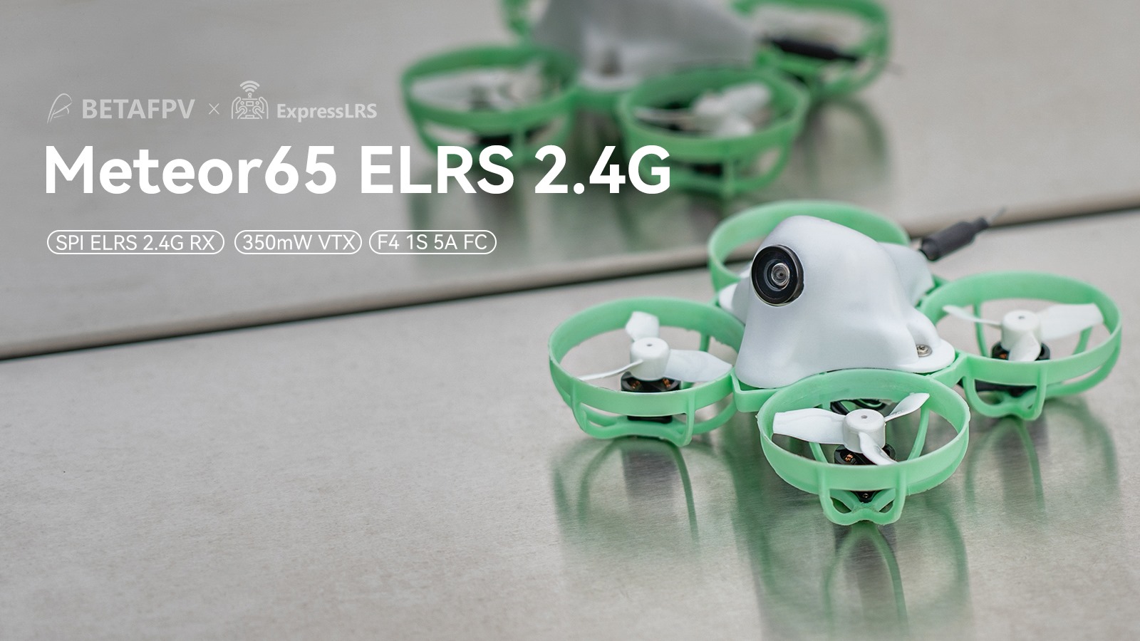
Change list:
- The FC board is the F4 1S 5A FC (ELRS 2.4G), with integrated BLHeli_S 5A ESC and SPI ExpressLRS 2.4G receiver.
- The VTX is?5.8G VTX M03?with the max 350mW output power.
Available @
BetaFPV:?https://betafpv.com/products/meteor65-brushless-whoop-quadcopter-1s
BetaFPV Meteor75 ELRS
Meteor75 ELRS has the newest F4 1S 5A FC and new M03?VTX, motors were changed to the lighter?0802SE 19500KV and the props how are Gemfan 40mm biblades?propellers. BetaFPV Meteor75 has received the most changes of all Meteor series – almost all the components were changed/upgraded. It became almost 5 grams lighter?compared to the Meteor75 with FrSky receiver.

Change list:
- The FC board is the?F4 1S 5A FC (ELRS 2.4G), with integrated BLHeli_S 5A ESC and SPI ExpressLRS 2.4G receiver.
- The VTX is 5.8G VTX M03?could provide highest 350mW output power.
- The motors are??0802SE 19500KV
- The propellers are Gemfan 40mm 2-blades.
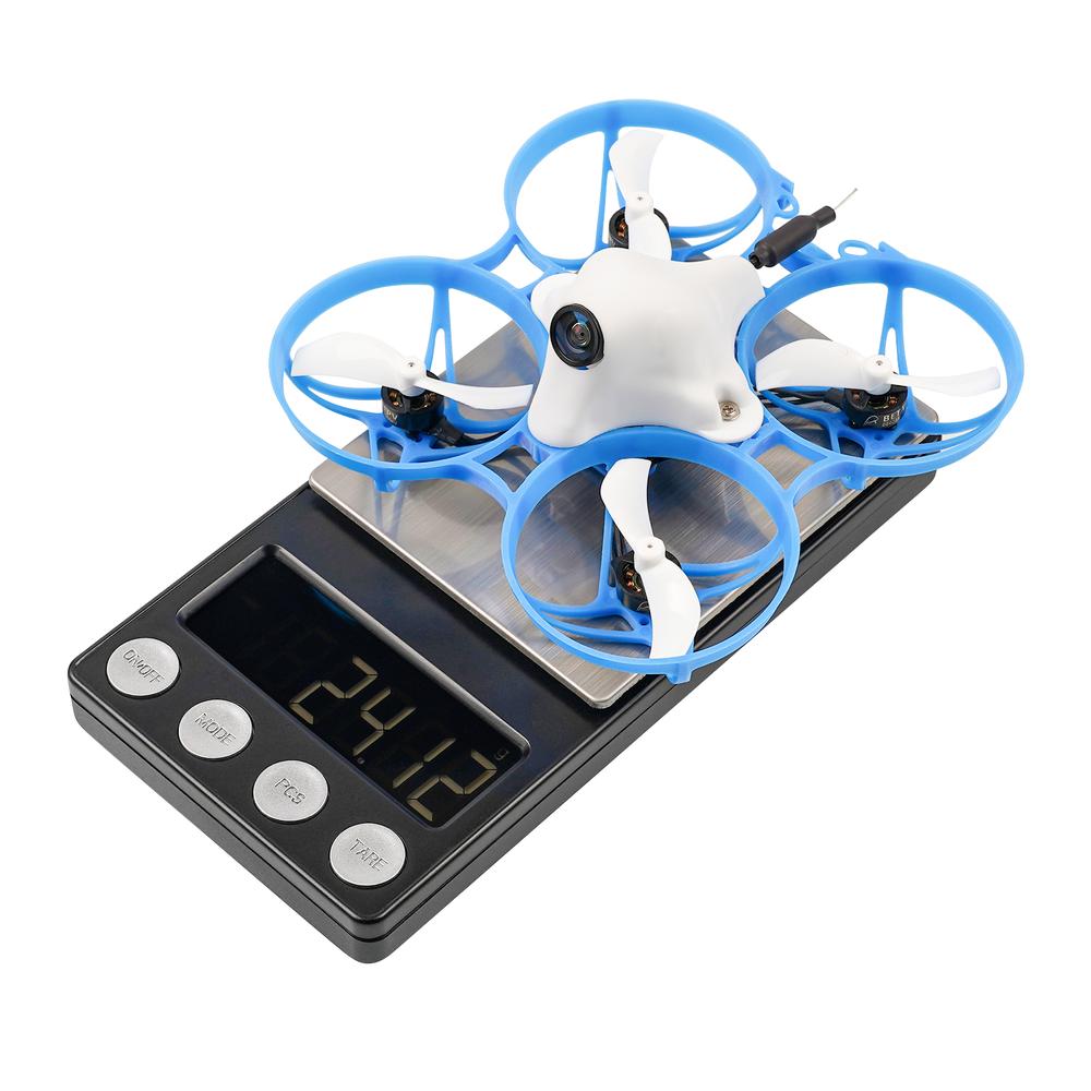
The weight of the Meteor75 ELRS is 24 grams.
Available @
BetaFPV:?https://betafpv.com/products/meteor75-brushless-whoop-quadcopter-1s
BetaFPV Meteor85 ELRS (Beta85 Pro 2)
Meteor85 ELRS has new F4 1-2S 12A FC, new M03?VTX, C02 camera was upgraded to Caddx Ant?camera together with more durable canopy.
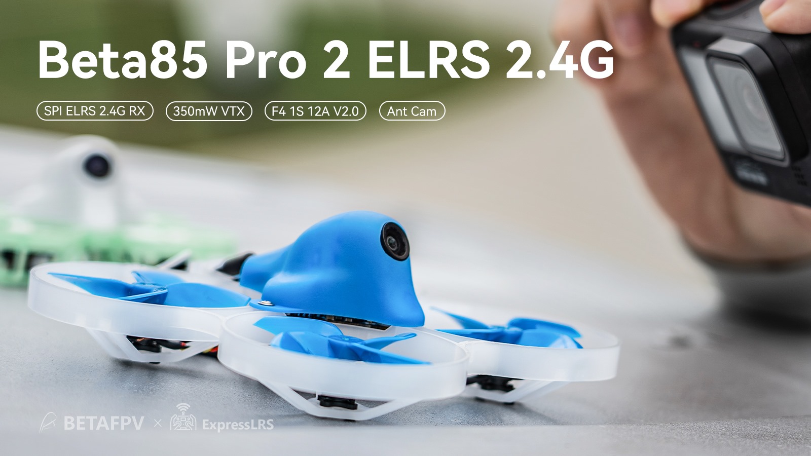
Change list:
- The FC board is the?F4 1-2S 12A? V2 FC (ELRS 2.4G), with integrated BLHeli_S 12A ESC and on board SPI ExpressLRS 2.4G receiver (with external antenna)
- The VTX is 5.8G VTX M03?could provide maximum of?350mW output power.
- BetaFPV C02 camera replaced by Caddx Ant.
Available @
BetaFPV:?https://betafpv.com/products/beta85-pro2-whoop-quadcopter-2s
]]>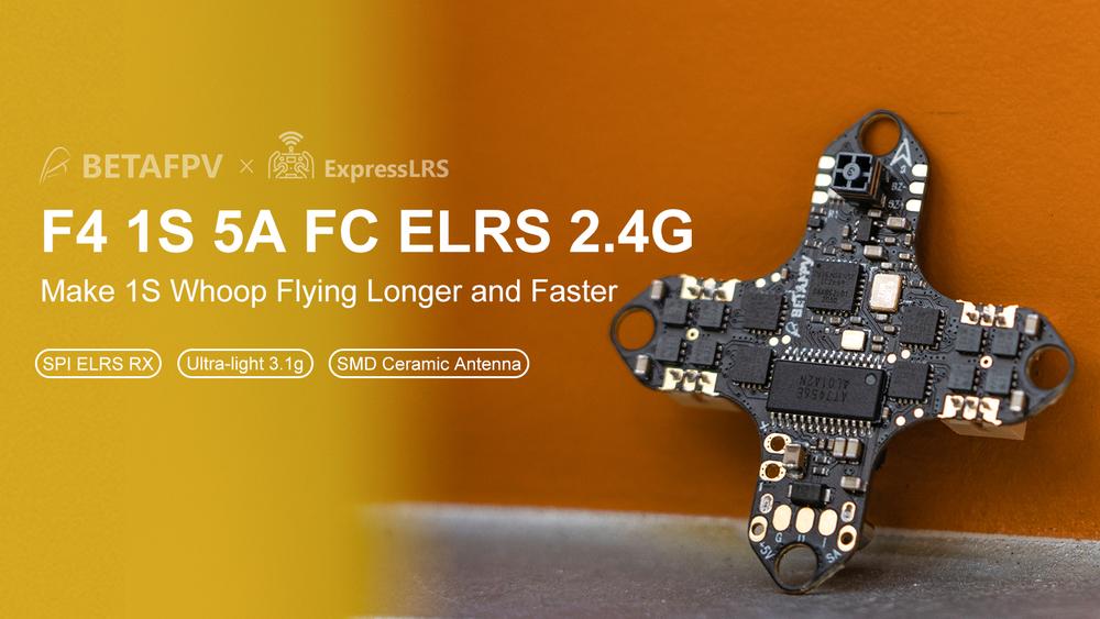
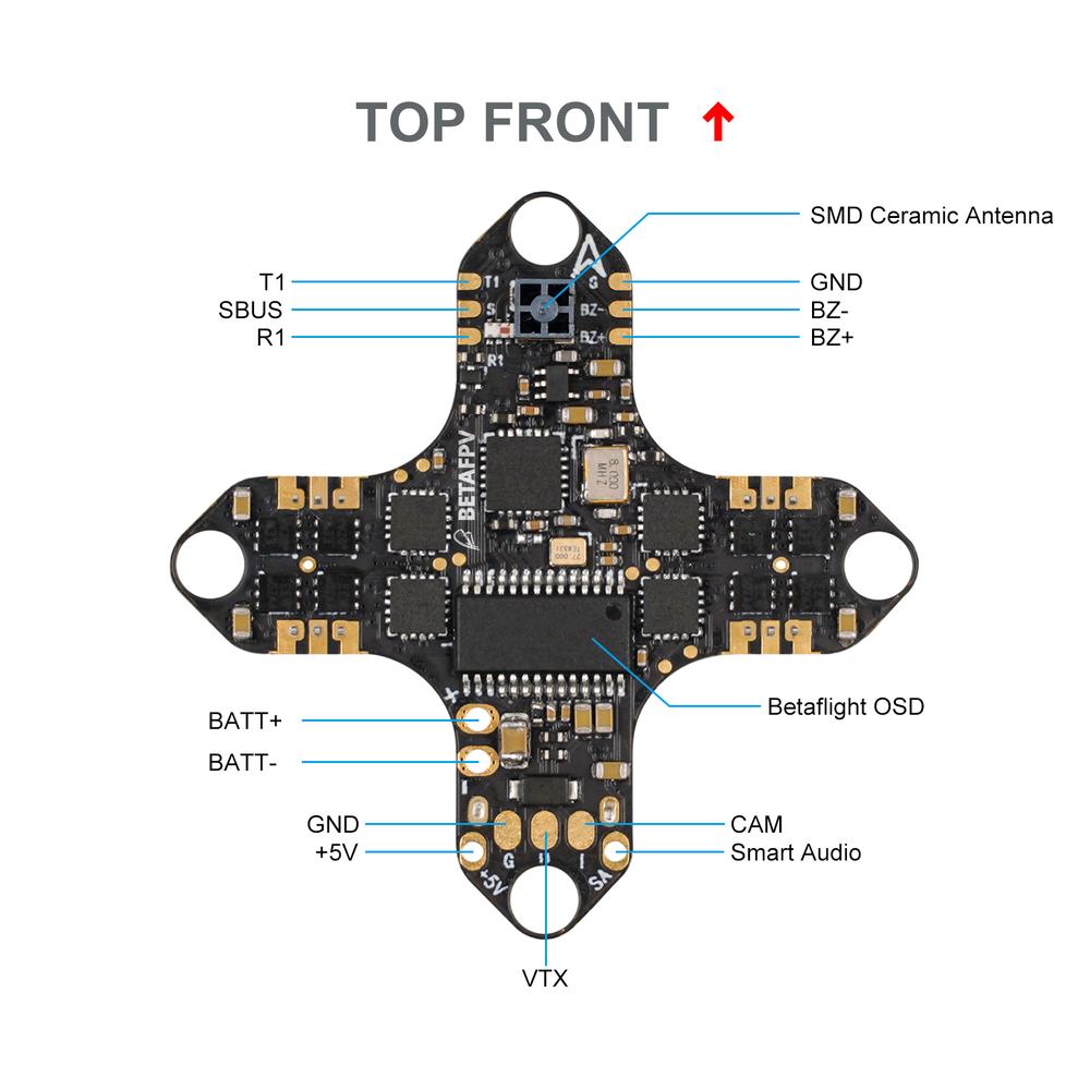
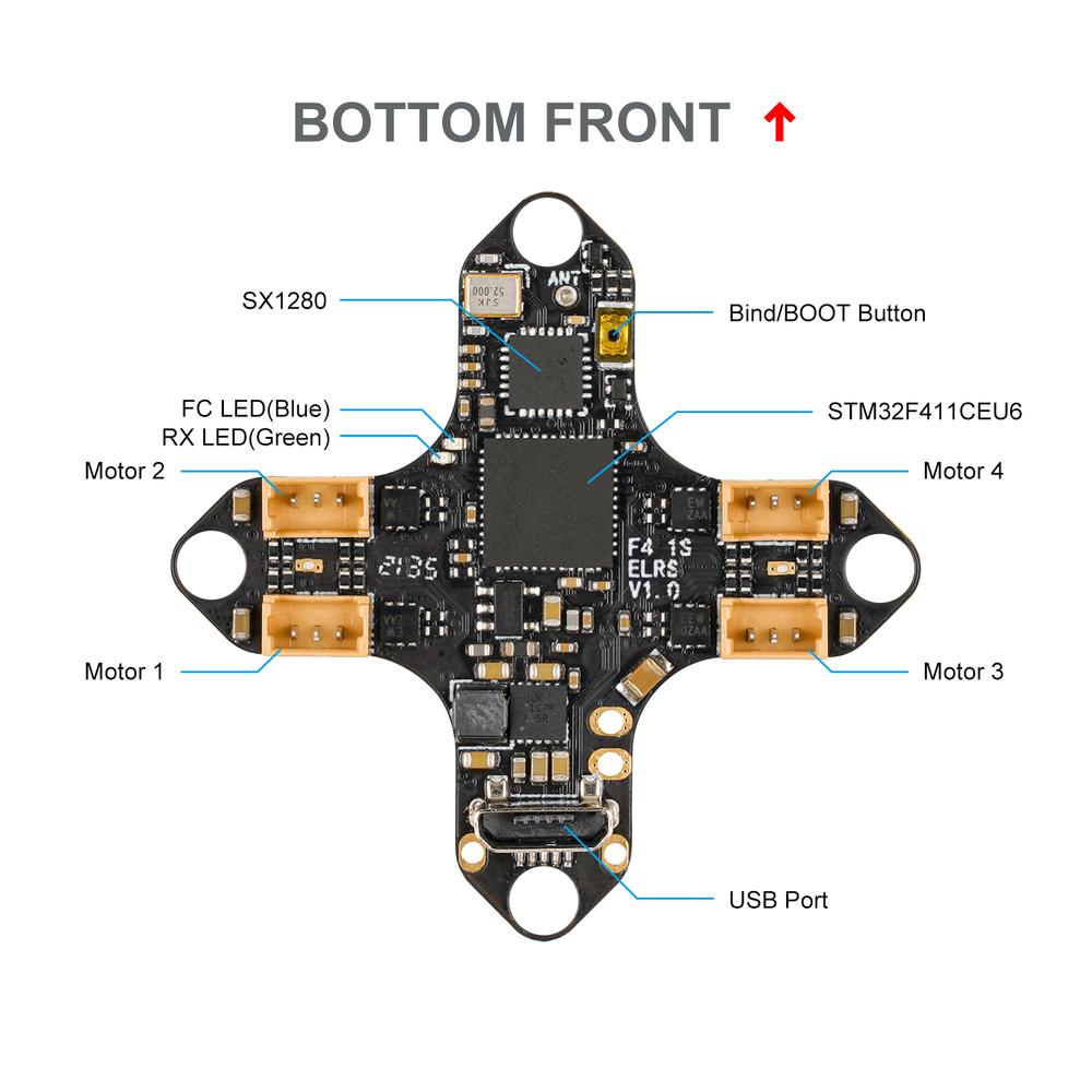
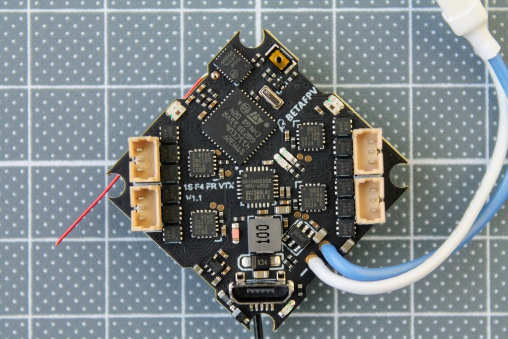
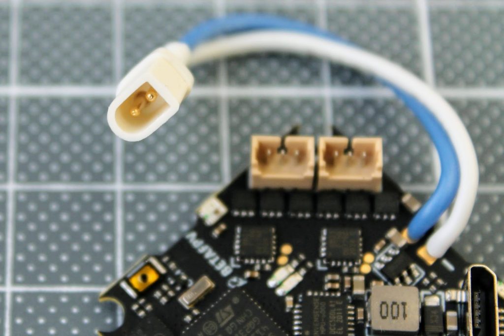
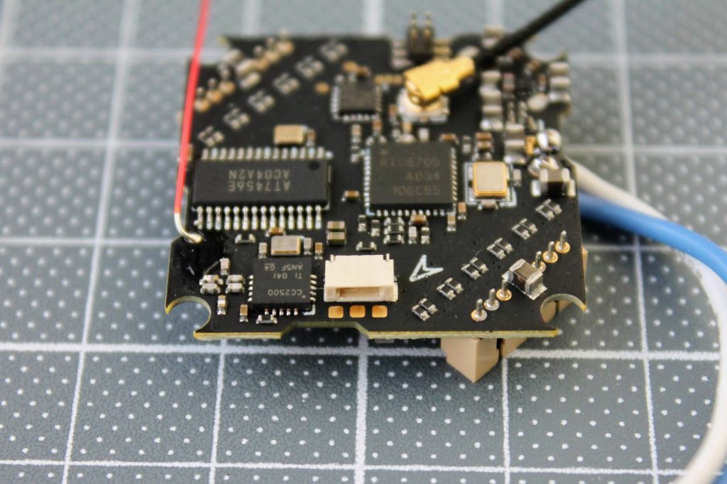
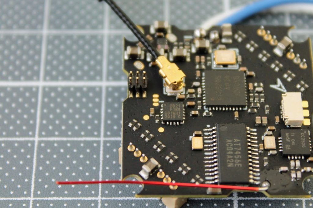
BetaFPV F4 1S ELRS flight controller has SPI ExpressLRS receiver with on board SMD ceramic antenna. Board supports 1S and provides uo to 5A for motors. Because of the shortage of the chips in the market, BetaFPV had to exchange the MPU-6000 gyro into?ICM-20689.
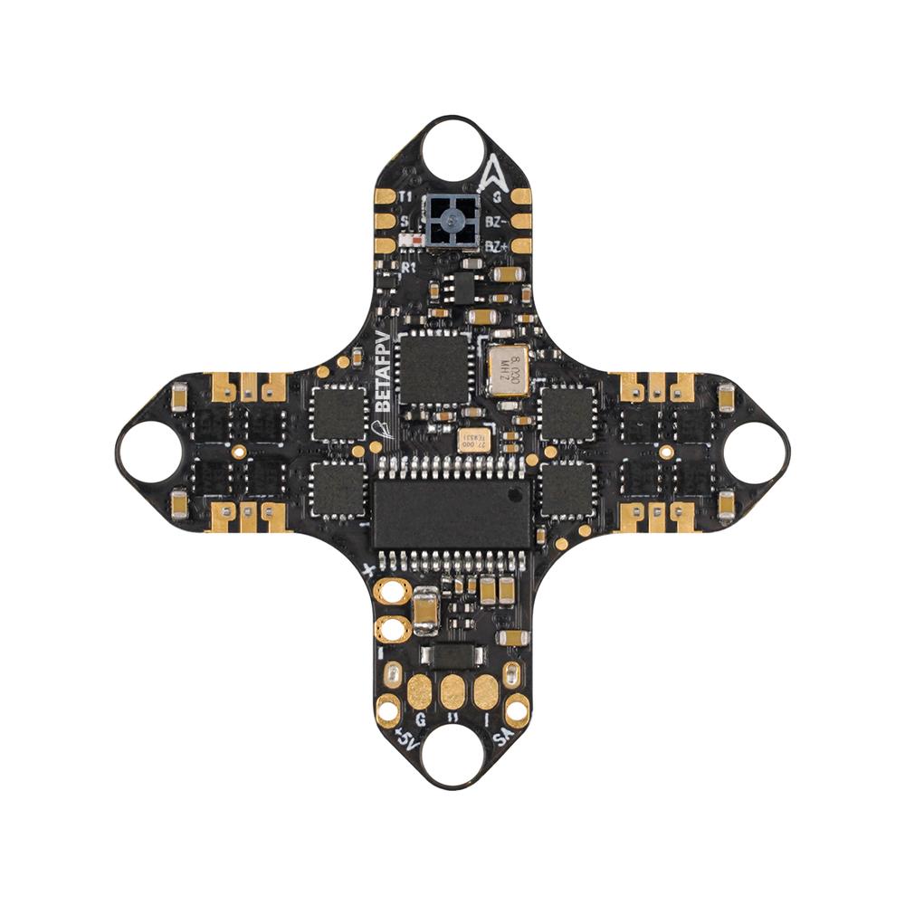
The total weight of the BetaFPV F4 1S ELRS?AIO board with on board SMD antenna is only 3.13 grams.
BetaFPV F4 1S ELRS AIO Whoop board pinout diagram.
Available @
BetaFPV:?https://betafpv.com/products/f4-1s-5a-aio-brushless-flight-controller-elrs-2-4g
Specifications:
CPU: STM32F411CEU6 ( 100MHZ )
Six-Axis: ICM-20689/MPU-6000
Built-in Receiver: SPI ExpressLRS 2.4G
Receiver antenna: 2.4GHz SMD ceramic antenna
Size: 29mm x 29mm, fully mounting pattern compatible with the whoop frame in the current market
Firmware version:?betaflight_4.3.0_STM32F411_norevision
OSD: Built-in BetaFlight OSD
Recommend VTX: >=200mW, like BetaFPV M03 25-350mW 5.8G VTX
Power Cable: 55mm, with?BT2.0 connector
Power supply: 1S
Current: 5A continuous and peak 6A (3 seconds)
Support BLHeli_S firmware
Factory?firmware:?O_H_5_48_REV16_8.HEX
Signal Support: D-shot150, D-shot300, D-shot600, Oneshot125, Multishot, PWM
Weight:?3.13g?(no power cable included)
]]>
Lets take a look at the BetaFPV 2.4GHz ExpressLRS?Nano TX and RX modules.
Specifications
BetaFPV Nano TX transmitter
 |
 |
Available @ BetaFPV:?https://betafpv.com/collections/expresslrs-series/products/elrs-nano-tx-module
Banggood:?https://www.banggood.com/search/betafpv-expresslrs.html
Packet refresh rate: 25Hz/50Hz/100Hz/200Hz (915MHz/868MHz)
25Hz/50Hz/150Hz/250Hz/500Hz (2.4GHz)
RF output power: 100mW/250mW/500mW
Frequency bands (Nano RF Module 2.4G version): 2.4GHz ISM
Frequency bands (Nano RF Module 915MHz/868MHz version): 915MHz FCC/868MHz EU
Input voltage: 5V~12V
USB port: Type-C
BetaFPV Nano receiver
 |
 |
Available @ BetaFPV: https://betafpv.com/collections/expresslrs-series/products/elrs-nano-receiver
Banggood:?https://www.banggood.com/search/betafpv-expresslrs.html
Weight: 0.7g (receiver only, w/o antenna)
Size: 12mm*19mm
Telemetry power: 20dBm
Frequency bands (Nano receiver 2.4G version): 2.4GHz ISM
Frequency bands (Nano receiver 915MHz/868MHz version): 915MHz FCC/868MHz EU
Input voltage: 5V
Antenna connector: IPEX MHF
Closer look
BetaFPV ExpressLRS Nano TX module comes with two antennas – linear whip style dipole antenna and Moxon type antenna
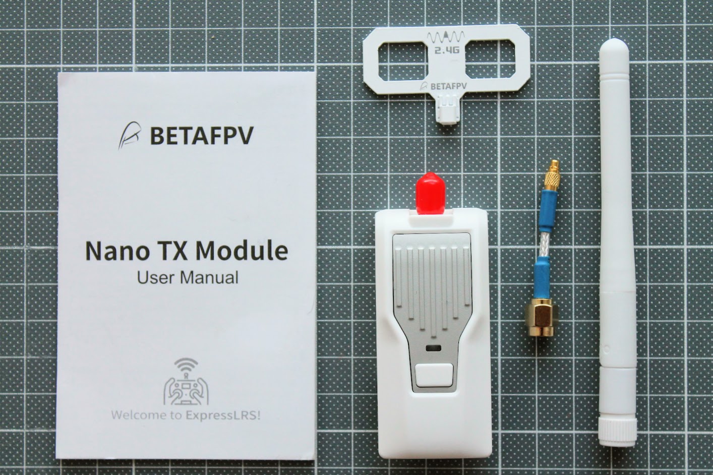
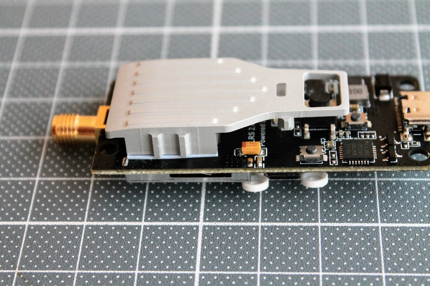
Disassembled BetaFPV Nano TX module.
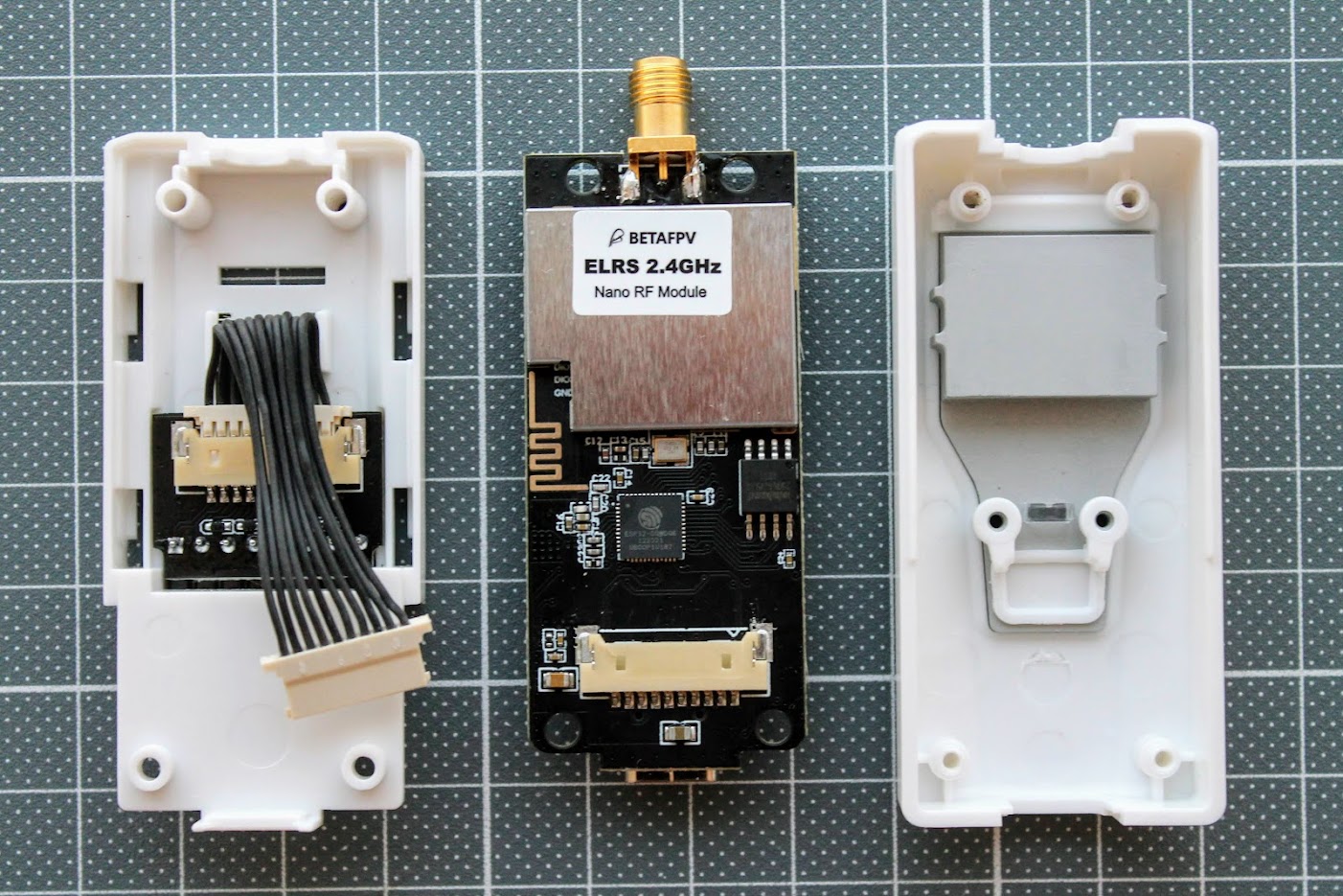
BetaFPV Nano TX module has thick metal heatsink for cooling the RF chip. It is exposed to the outside and can get pretty hot on higher power output levels. This heatsink does the job well and the module does not overheat even on the 500mW output.
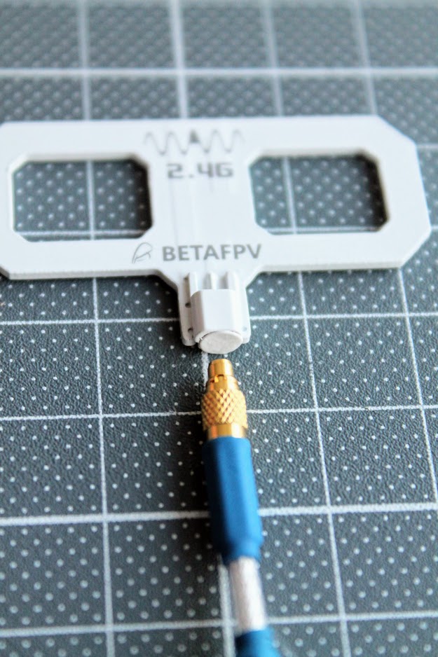
The supplied Moxon type antenna has a cover on the MMCX connector. You should remove it before plugging the MMCX pigtail.
 |
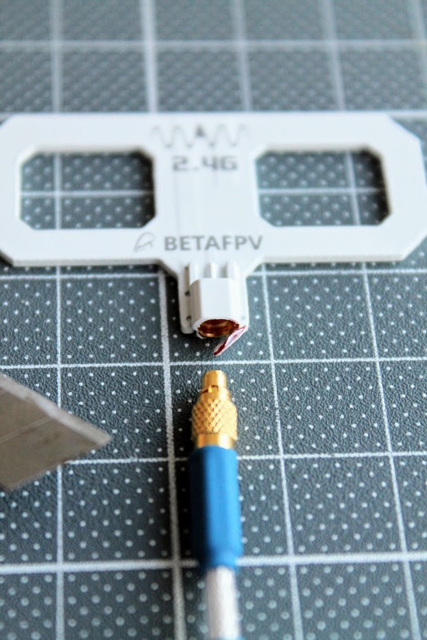 |
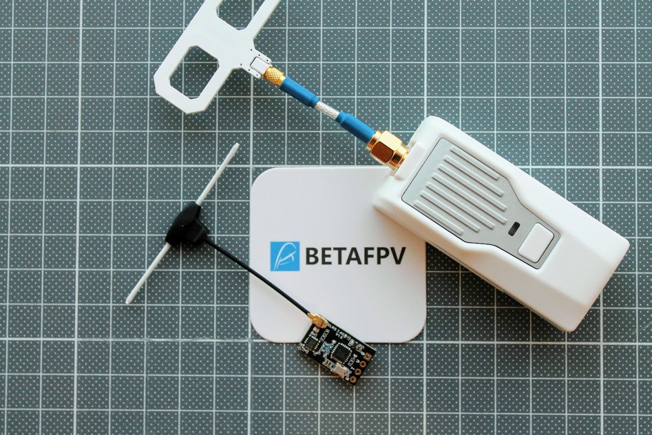
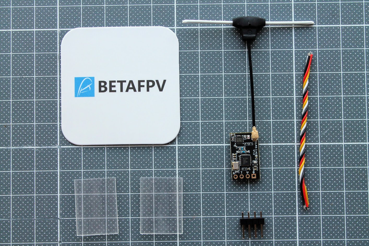
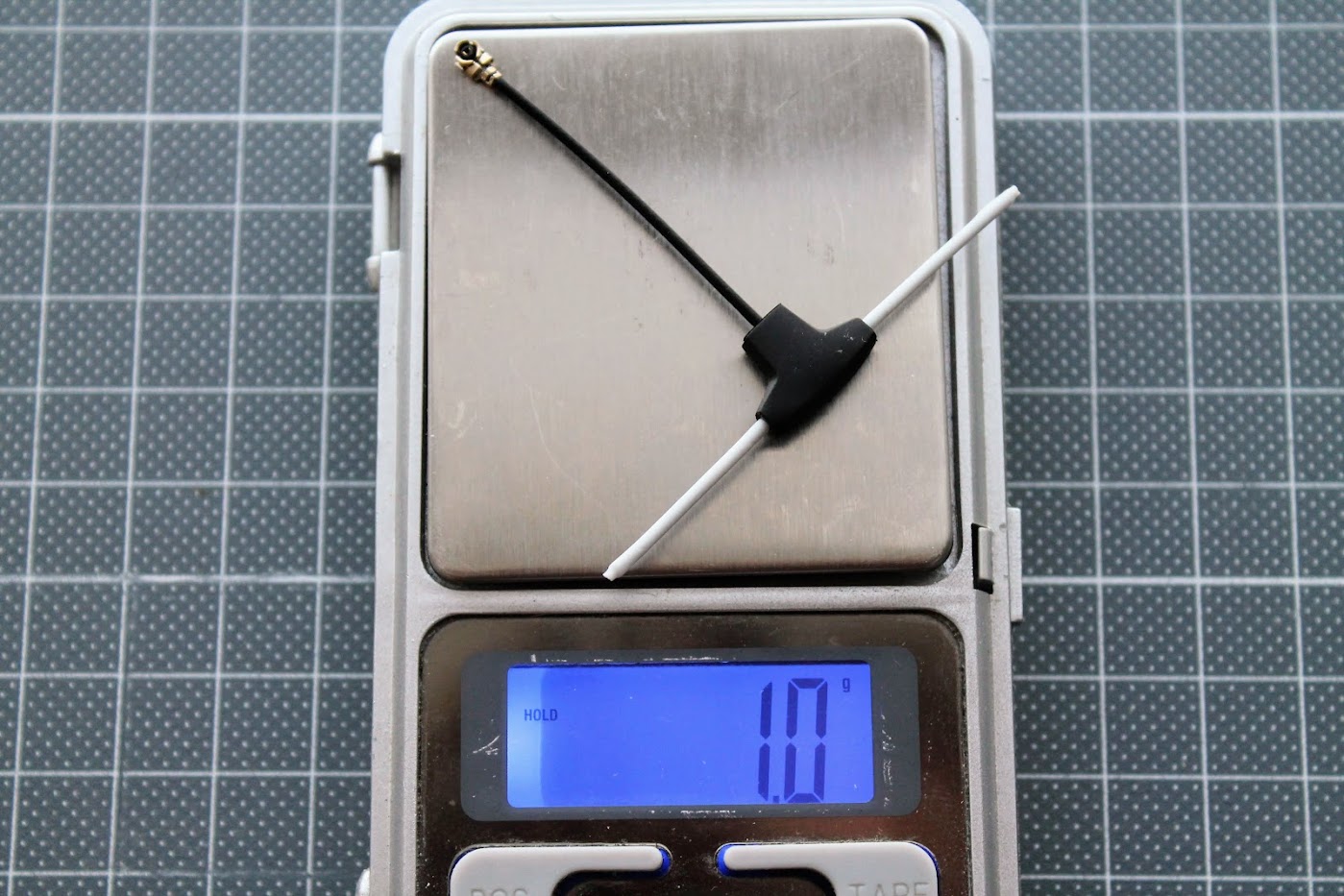
BetaFPV ExpressLRS Nano receiver comes with T-style dipole antenna, silicone wires, two heat shrinks and a pin header if you need to solder one.
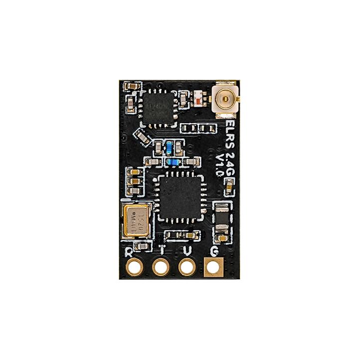
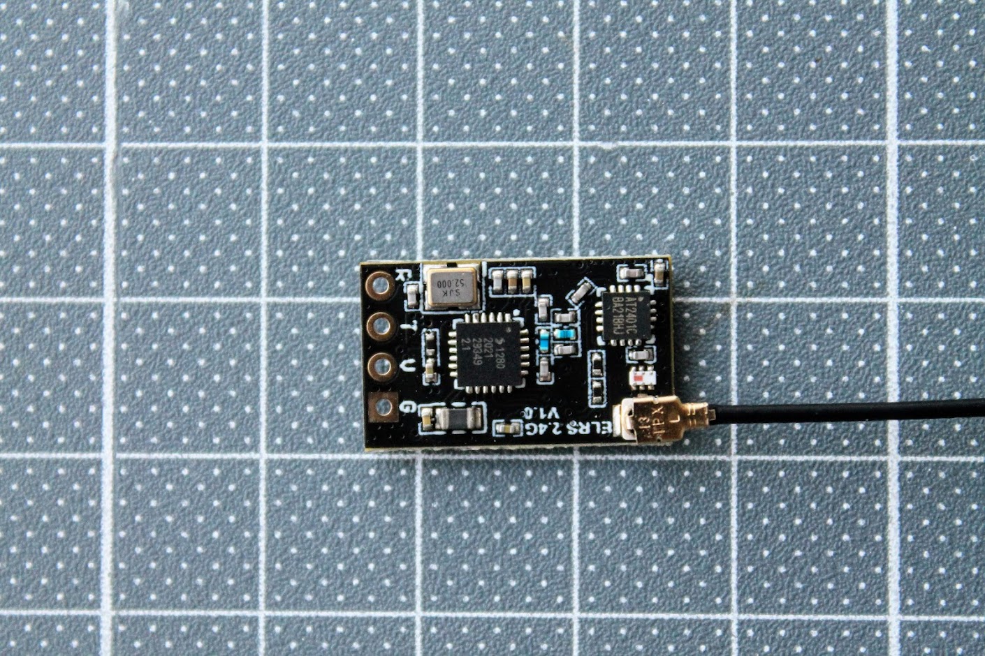
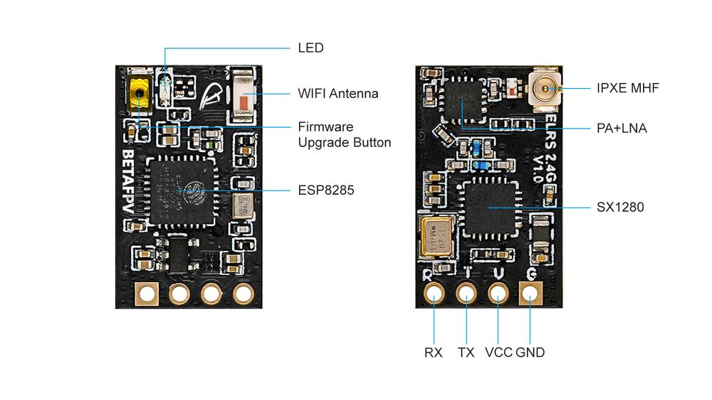
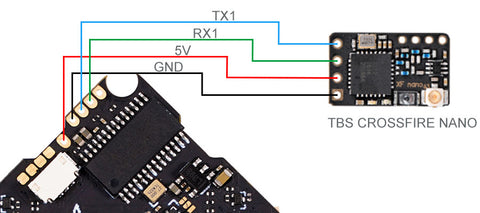
You can see the standard pinout pattern R T V G (RX, TX, +V, GND) on the antenna side. This is the same pinout as on TBS Crossfire Nano receiver, and is recommended design pattern for all ExpressLRS receivers.
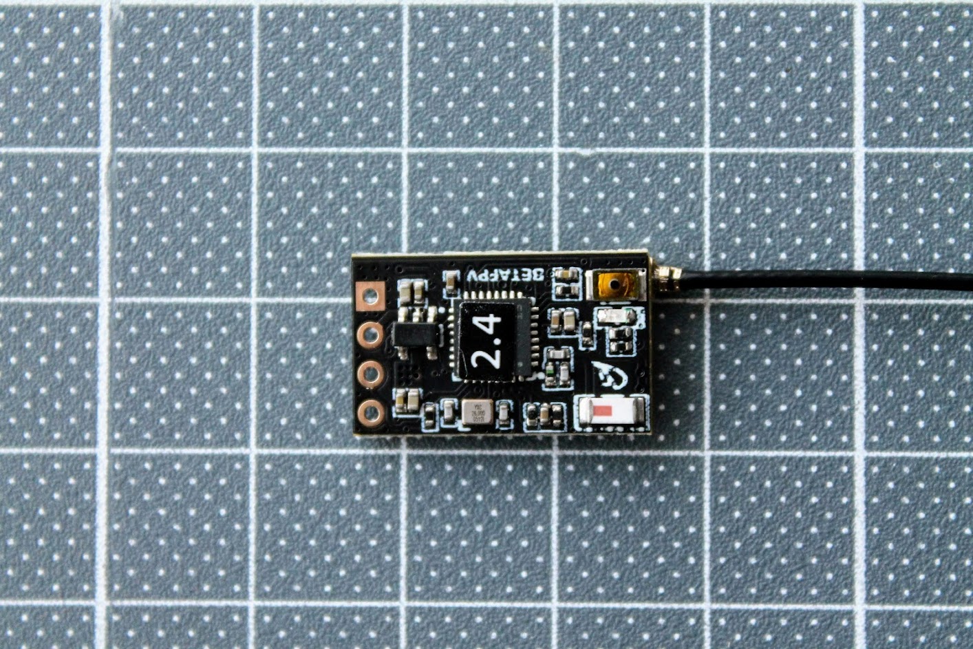
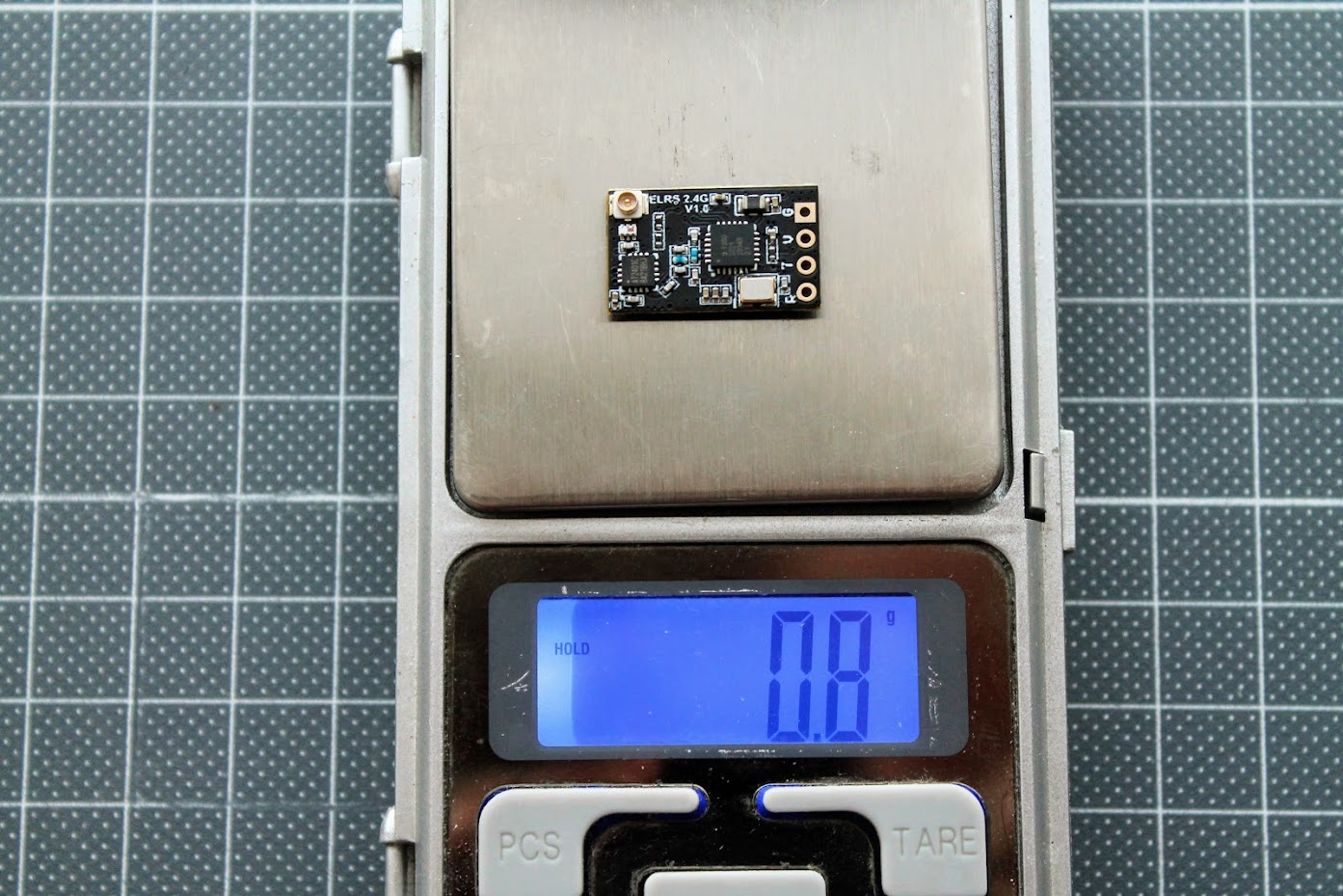
There is a ceramic antenna for WIFI connectivity, the boot button and the LED on the other side of the receiver.
The weight of the bare BetaFPV Nano receiver is only 0.8 grams.
The weight of the supplied T-style antenna is 1 gram.
And the total weight of receiver and antenna is 1.8 grams.
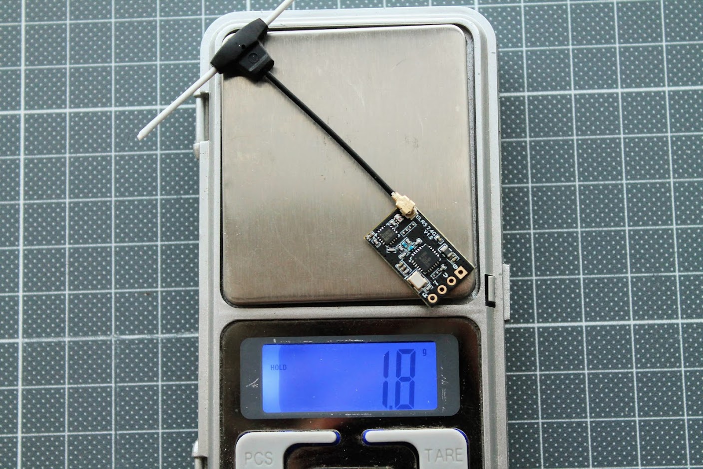
BetaFPV Nano receiver is the first and (so far) the only receiver with power amplifier (PA+LNA). It has 100mW telemetry output and in theory better sensitivity (longer range).
BetaFPV also sells the JR Lite to JR?type (or so called Nano to Micro) adapter box.
BetaFPV adapter:? https://betafpv.com/collections/rx-tx/products/micro-nano-module-adapter
BetaFPV TX module firmware upgrade
There are two options how to upgrade the TX module firmware – via WIFI or via UART(USB). For WIFI method you will need the OpenTX radio with ExpressLRS Lua script running. For UART method you can connect the TX module directly to the PC and you don’t need the Radio for flashing the ExpressLRS firmware to TX module.
Compiling the firmware
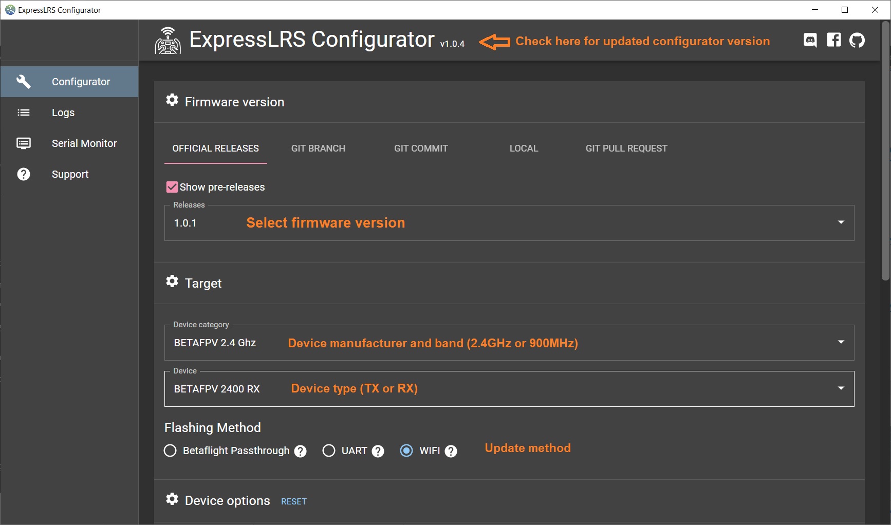
First you need to compile the firmware with the ExpressLRS Configurator. Select the firmware version, device type and flashing method.
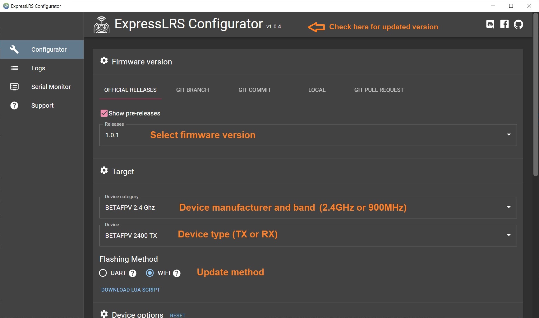
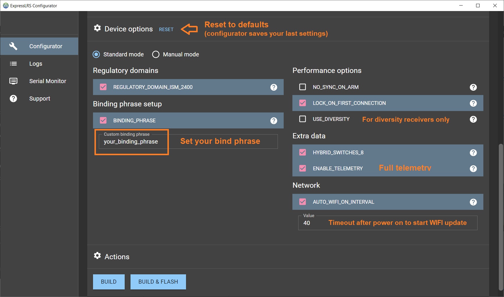
Set the device options.
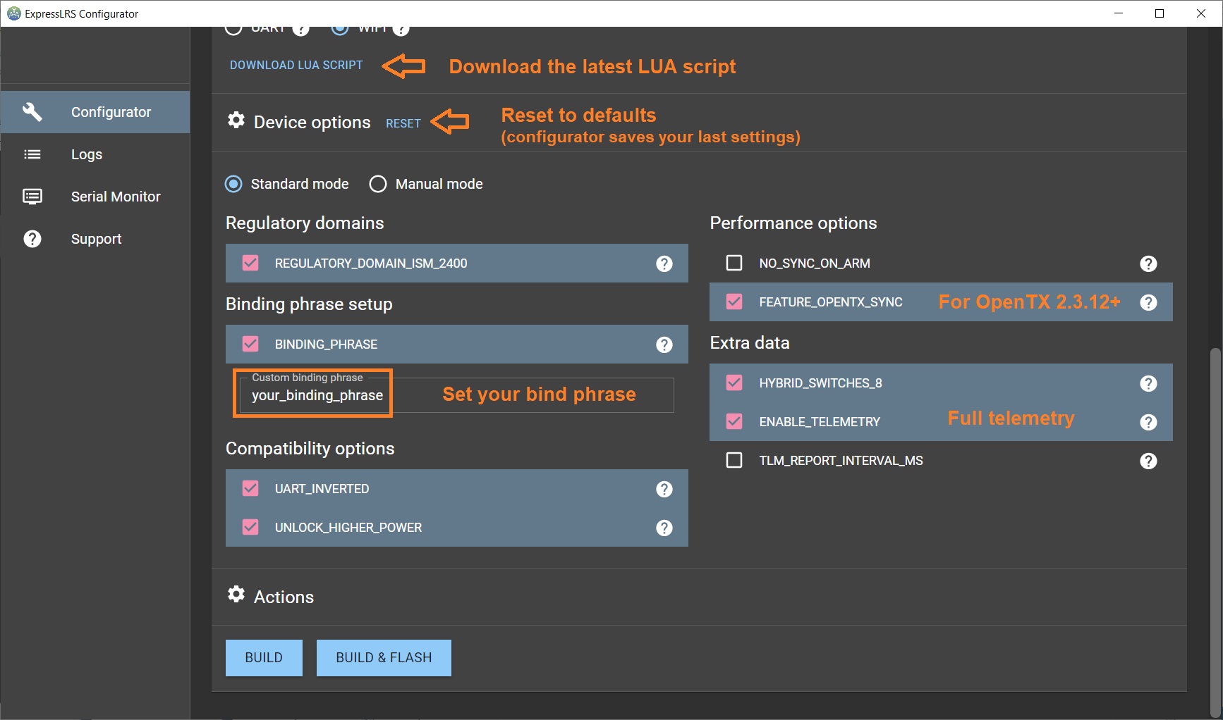
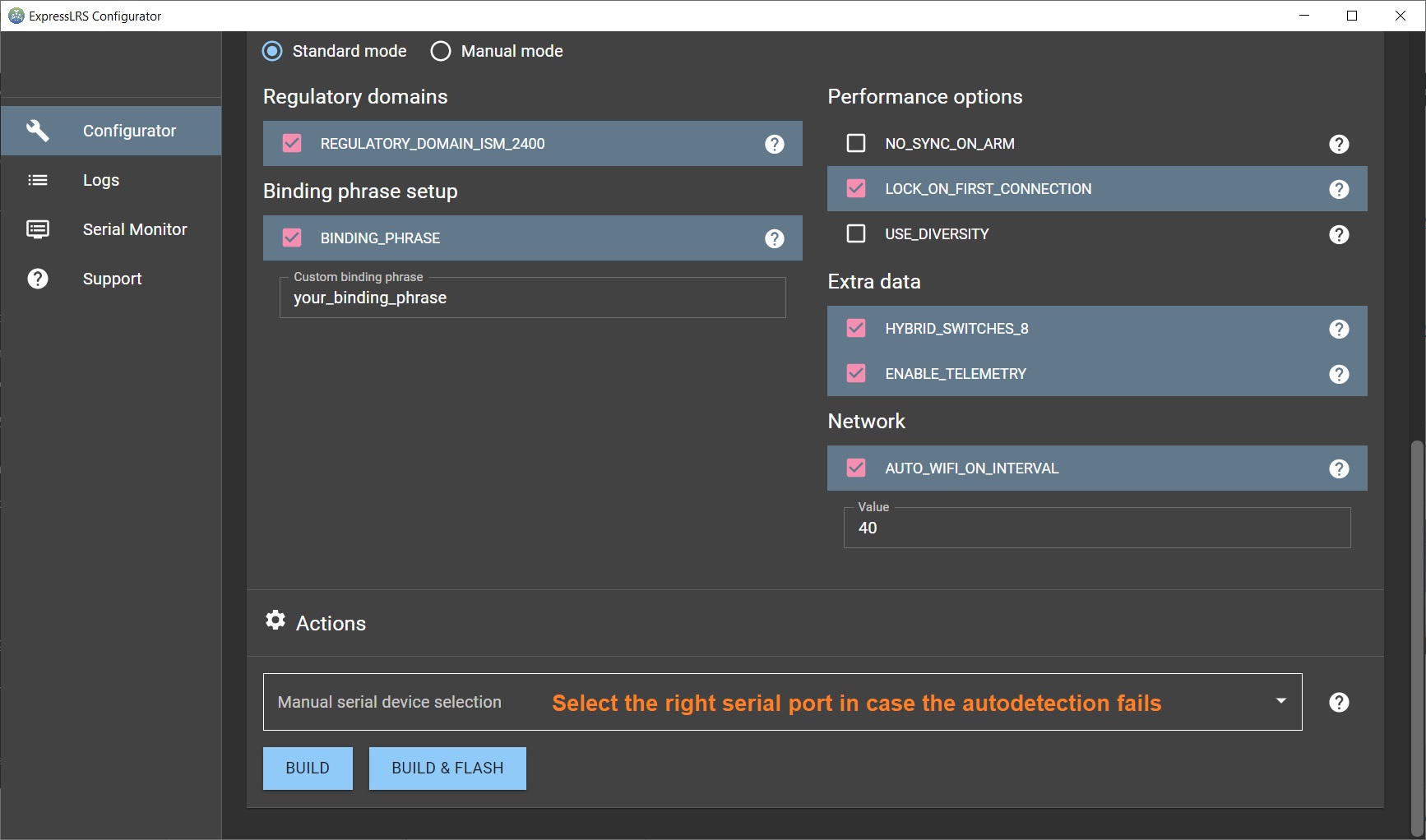
And press the [Build] button. The compiling result should be thefirmware.bin file that can be uploaded via WIFI or UART.
Via WIFI
Select?WIFI Update?from the ELRS Lua script. The TX module will enter into the WIFI mode. Then you have to connect your PC to the WIFI Hotspot the TX module created. It will show up in your network as?ExpressLRS TX Module, and the password is expresslrs. Then open the browser and go to a specific IP Address http://10.0.0.1/. In the web page, select the the compiled firmware file?firmware.bin? by pressing the [Choose file] button. Hit the [Update] button
Read more about the updating the ExpressLRS firmware here:?ExpressLRS?– Complete Guide
Via UART?(USB)
For flashing via the UART, you need to connect the TX module to the PC via USB-C cable.
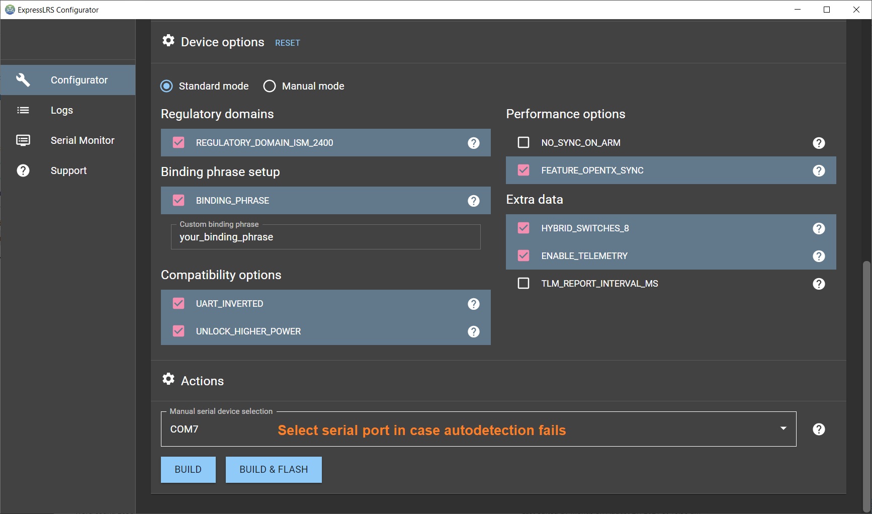
Select [Build & Flash] button when compiling the firmware in the ExpressLRS Configurator. The configurator will compile and try to upload to the detected serial port. If ExpressLRS configurator somehow fails to detect the serial port, then you should set the port manually.
Read more about the updating the ExpressLRS firmware here:?ExpressLRS?– Complete Guide
BetaFPV TX update via UART problem
The first batch of the BetaFPV ExpressLRS TX modules have hardware issue, which prevents the module to automatically go into UART firmware update mode.?BetaFPV forgot to add a capacitor on the EN pin of the ESP32, so it doesn’t reset properly. You might get the “Failed to connect to ESP32: Tined out waiting for packet header” error.
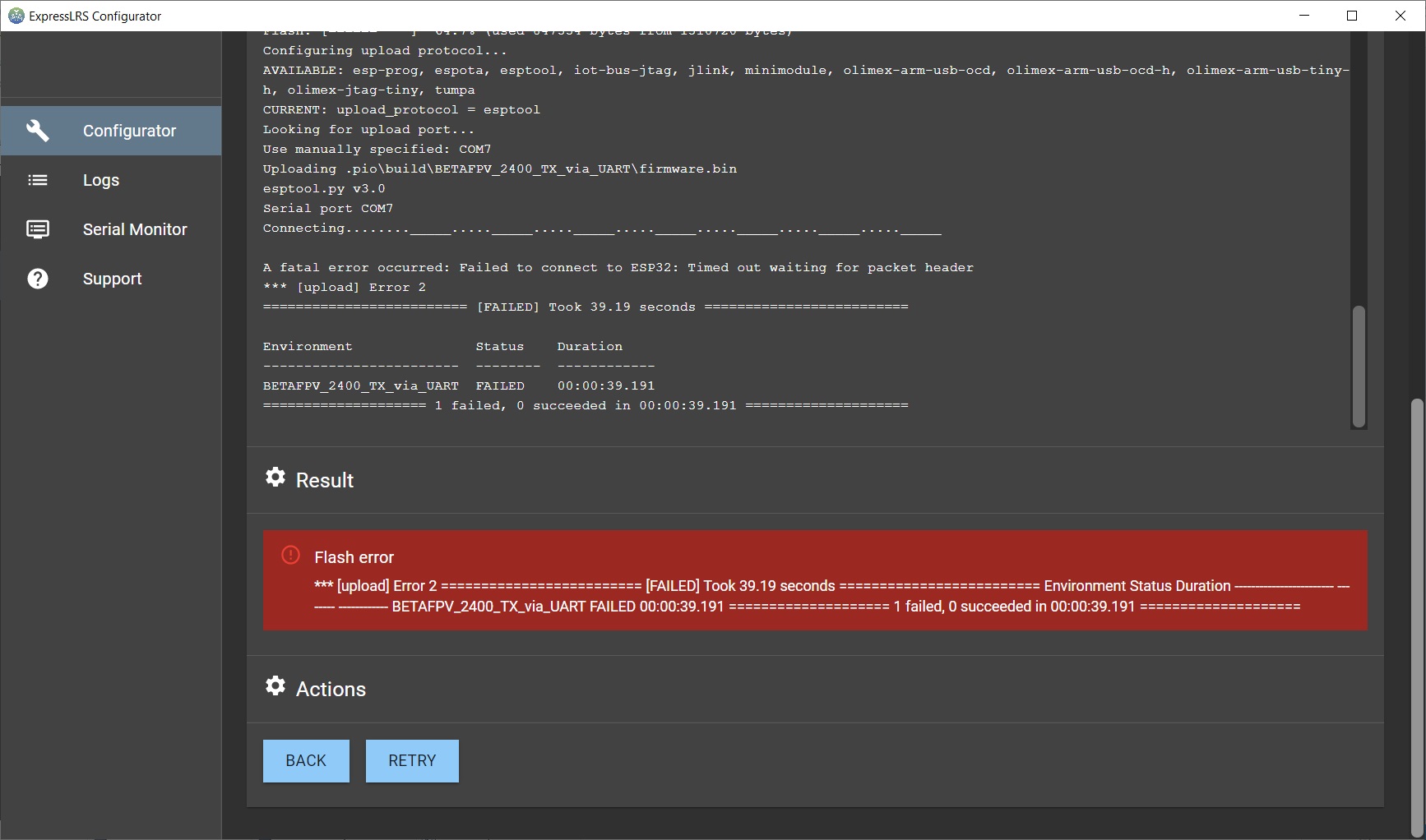
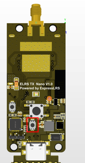
If you have this issue, the you can still use flashing by WIFI option or you can open the TX module and press the EN button while uploading the firmware via UART (USB), pictured below.
 |
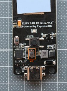 |
This can be fixed by adding small SMD capacitor to the circuit.
Nice job done fixing the BetaFPV ExpressLRS TX module by QUADMOVR.
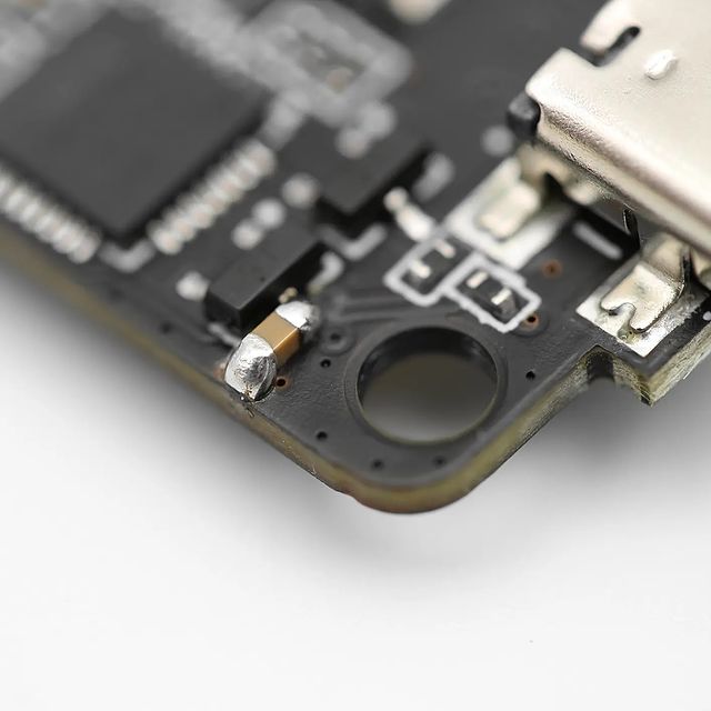
UART update fix by QUADMOVR
BetaFPV Receiver firmware upgrade
There are three ways how to upgrade the receiver firmware – via WIFI, via Betaflight Passthrough or via UART. For UART mode you need to connect the USB to TTL dongle to the ExpressLRS receiver. So you should use WIFI or Betaflight Passthrough, for the first one you only need to power the ExpressLRS receiver ad for the second one you need it to connect to the Flight controller, running Betaflight firmware.
Compiling the firmware
First you need to compile the firmware with the ExpressLRS Configurator. Select the firmware version, device type and flashing method.
Set the device options.
And press the [Build] button. The compiling result should be thefirmware.bin file that can be uploaded via WIFI or
Via WIFI
Power on the receiver, but keep your radio turned off. Receiver will enter into the WIFI mode after the AUTO_WIFI_ON_INTERVAL?timeout and the led on the receiver should start blinking fast. Then you have to connect your PC to the WIFI Hotspot the RX module created. It will show up in your network as?ExpressLRS RX Module, and the password is expresslrs. Then open the browser and go to a specific IP Address http://10.0.0.1/. In the web page, select the the compiled firmware file?firmware.bin? by pressing the [Choose file] button. Hit the [Update] button
Read more about the updating the ExpressLRS firmware here:?ExpressLRS?– Complete Guide
Via Betaflight Passthrough
Connect the Flight Controller to the PC via USB cable. Select?[Build & Flash] button when compiling the firmware in the ExpressLRS Configurator. The configurator will compile and try to upload to the detected serial port. If ExpressLRS configurator somehow fails to detect the serial port, then you should set the port manually.
OpenTX configuration
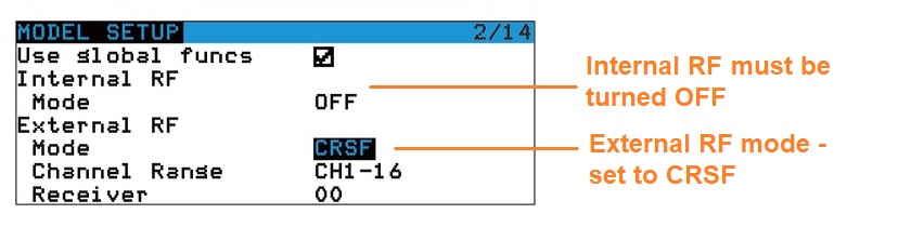
Open?“MODEL SETUP” in the OpenTX radio, turn OFF the “Internal RF“, enable “External RF” and select “CRSF” as the protocol.
Download and install ExpressLRS LUA script (ELRS.lua file) in to the OpenTX radio.
Read more about the ExpressLRS LUA script here:?ExpressLRS?– Open Source Long Range radio control system- Complete Guide
Run the ELRS Lua script. You should see the similar options setup window:
ExpressLRS Binding
BetaFPV Nano TX module could enter into binding mode via ELRS.Lua script.?Alternatively you can short press button on the module to enter the binding mode. Note, that TX module LED does not indicate the binding mode. TX module will automatically stop biding after 5 seconds, so you need to set the binding mode in receiver first.
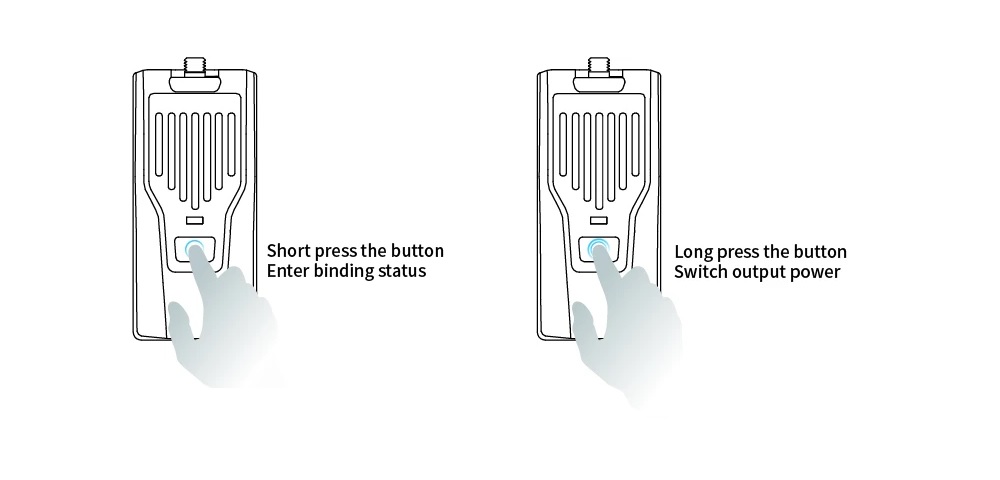
Power output
You can change the power output level by using ERLS.lua script or by long pressing the power/bind button on the TX module. Power output level cycles between 100-250-500mW and the led color changes accordingly.
The RF TX module output power and LED indication as shown below.
| LED Color | RF output power |
| Blue | 100mW |
| Purple | 250mW |
| Red | 500mW |
Links
BetaFPV ExpressLRS?TX on BetaFPV:?https://betafpv.com/collections/expresslrs-series/products/elrs-nano-tx-module
BetaFPV ExpressLRS?RX on BetaFPV:?https://betafpv.com/collections/expresslrs-series/products/elrs-nano-receiver
BetaFPV ExpressLRS on Banggood:?https://www.banggood.com/search/betafpv-expresslrs.html
BetaFPV Nano TX user manual:?https://support.betafpv.com/hc/en-us/article_attachments/4403878641433/Manual_for_Nano_RF_TX_Module.pdf
BetaFPV Nano receiver user manual:?https://support.betafpv.com/hc/en-us/article_attachments/4403870819737/Manual_for_Nano_Receiver.pdf
ExpressLRS guide:?ExpressLRS –? Open Source Long Range radio control system – Complete Guide
Disclaimer: This item was supplied by BetaFPV for a fair and unbiased review. BetaFPV never asked for a positive review and never influenced my opinion in any way. I’m trying my best to stay uninfluenced and give only my own, honest and as much as possible unbiased opinion. All affiliate links, if there are any, help me purchase items for future reviews and tests.
]]>LiteRadio 2 features/specifications
Real gimbals (smaller size than full sized radio)
8 channels
4 switches: 2 – two pos and 2 – three pos
Optional protocols: Bayang, Frsky D8, Frsky D16 FCC ans D16 LBT
Runs on OpenTX firmware
Can be used as USB joystick for simulators
Trainer function
Bind and setup functions
BetaFPV LiteRadio 2 radio transmitter comes with 2 pcs BetaFPV 300mAh batteries and 1S BT2.0 battery charger/tester.
![]()
BetaFPV LiteRadio 2 has real gimbals with adjustable height sticks. Stick thread is 3mm.
![]()
Radio has power button in the middle. You need to press the button for at least 2 seconds to turn the radio on and at least for 3 seconds to turn the radio off.
![]()
On the bottom side of the radio you can find the MicroUSB socket for connecting the radio to the computer and 3.5mm socket for trainer connection.
![]()
There are 4 switches located on the top side of the radio.
![]()
One three position and one two position switch on the each side.
![]()
On the back side of the transmitter you can find Setup and Bind buttons.
![]()
BetaFPV LiteRadio 2 is powered by 2S battery. There is a 2x 1S battery adapter for connecting two 2S batteries (that are supplied with the radio).
![]()
However the battery bay is too small and you need to figure out how to manage to fit the batteries inside.
![]()
Luckily there is small slot for battery leads and somehow you can fit them inside.
![]()
Fully charged BetaFPV 300mAh batteries last for about 1 hour and 15 minutes, when the LiteRadio 2 starts to flash the power button led.
BetaFPV LiteRadio 2 comes with the BT2.0 battery charger/tester. It is handy tool for checking the 1S BT2.0 battery voltage. It would be nice if the radio had internal charging circuit for charging two 1S batteries or one 2S battery internally.
![]()
Charger has two sockets for BT2.0 batteries.
![]()
The size and shape of the radio is perfect fit for thumbers. The same feel as having the game controller in hands. The pointer finger can access the switches easily.
![]()
However the LiteRadio 2 is just too small for comfortable use for pinchers and hybrid type users.
![]()
![]()
The power button has three color LED light. It is lit in GREEN while powering (starting) the radio, turns into RED if the sticks/switches check failed and turns into BLUE on normal operation.
![]()
Inside the radio
You have to unscrew the 8 screws to open the LiteRadio 2.
![]()
Mine came with one screw missing.
![]()
Inside you can find the main board, RF board, gimbals and switches.
![]()
Closer view of the left gimbal. You can see the metallic throttle tension bar. You can adjust the tension by screwing or unscrewing this bar.
![]()
Right gimbal with two springs.
![]()
Gimbals have simple potentiometers for each axis.
![]()
Closer look at the main board. On the top part of the board you can find the power supply circuit.
![]()
On the bottom part of the main board you can find the MicroUSB and trainer sockets as well as SW1 (setup) and SW2 (bind) buttons.
![]()
RF board has CC2500 RF Transceiver and CC2592 power amplifier/ range extender chips.
![]()
Below the RF board you can find the STM32F205 MCU chip. There are also SW16 bush button and JP15 socket for ribbon cable. Their purpose is unknown.
![]()
On the top of the radio case there is patch antenna attached.
![]()
RF module
![]()
![]()
Binding the receiver
In order to bind the receiver to the LiteRadio 2 you need to
- Power the transmitter on.
- Put the receiver into bind mode.
- Press the BIND button from the back of the transmitter.
![]()
The transmitter will enter the binding mode and last about 10 seconds, indicated by BLUE and RED LED flash alternately.
- Check if the receiver bonded successfully. If not, redo the steps above.
Binding procedure is really simple and I succeeded to bind the Meteor 65 from the first try.
How to switch the protocol (D16/D8 Version)
| LED Status | Protocol Version |
| Flash Once | Frsky D16 FCC |
| Flash Twice | Frsky D16 LBT |
| Flash Three Times | Frsky D8 |
Use with Simulators
In order to use this radio with PC simulators, just power the radio and connect it to the PC via micro USB cable. The LiteRadio 2 will be automatically detected as joystick device (Taranis).
Tip: if LiteRadio 2 is not recognized a joystick, then check this guide: OpenTX Radio not working in simulator issue fix
Setting up the radio
OpenTX settings are accessible only via OpenTX Companion. Only the special Companion version works with the LiteRadio 2.
Download link: https://github.com/BETAFPV/opentx/blob/LiteRadio/companion/companion-windows-2.2.4.exe
By default the LiteRadio 2 connects to the PC in USB Joystick mode. In order to connect the transmitter to the OpenTX Companion you need to Press and hold the SETUP button from the back of the transmitter. Press the power button on the transmitter. And then release both buttons. The power LED ring will not power on. Now the transmitter is in SETUP mode and you can scnnect the transmitter to the computer via a USB cable.
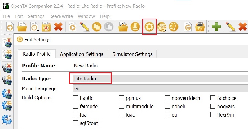
Open the OpenTX Companion software. Set the radio type to Lite Radio in the settings page.
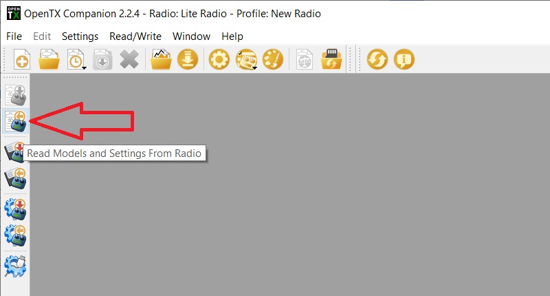
Download the all the Models and Settings from the Radio by pressing the button shown below.
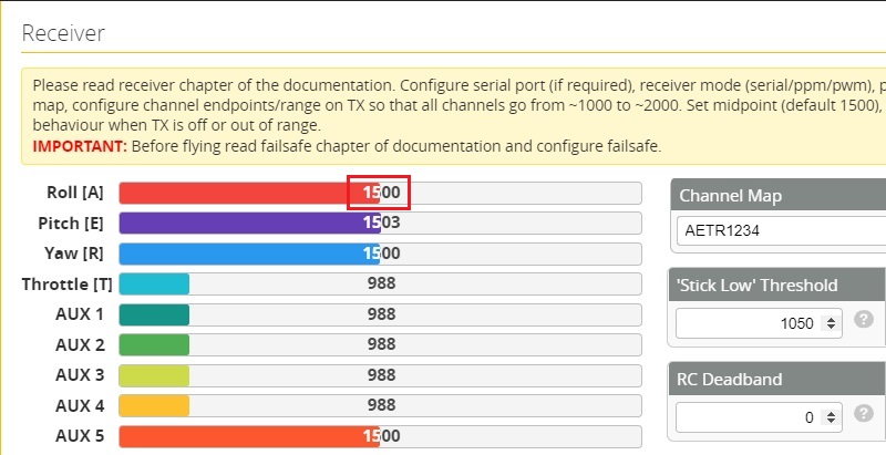
One of the most important settings that you might want to change is trim the center point (midpoint) of the Roll, Pitch and Yaw axis.
In order to calibrate the midpoint of the axis, press Edit Radio Settings button and select the Calibration tab.
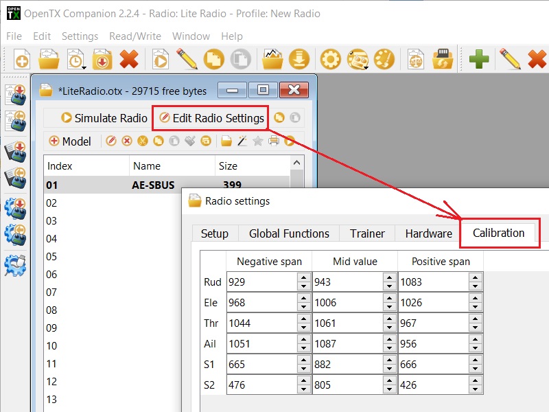
Check the midpoint value in the Betaflight Configurator Radio tab. In our case the Aileron (Roll) axis midpoint value is 1506 (should be 1500).

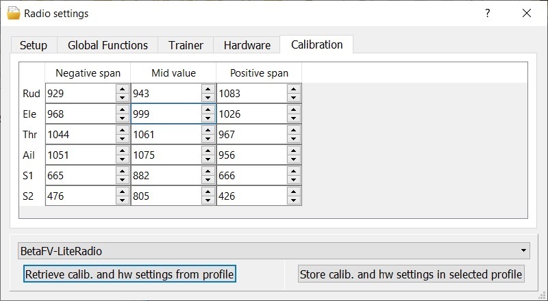
Calculate the calibrated Mid Value according to the equation below. Calibrated Mid Value = Original Mid Value + ( Mid Value from Betaflight Configurator – 1500) * 2
On our case it is Calibrated Mid Value = 1075 + (1506 – 1500)*2 = 1087
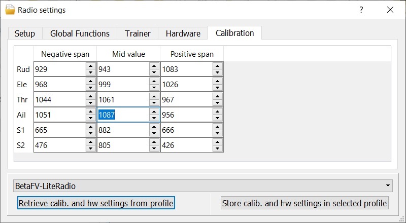
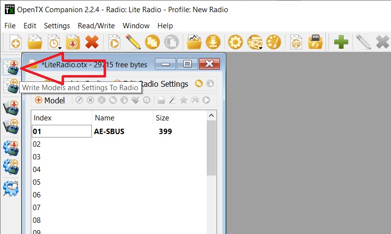
After this save the settings to the radio by pressing Write Models and Settings To Radio button.
That’s how the calibration of the midpoint is done. Now the Roll axis is perfectly centered.
Conclusion
The small size of the BetaFPV LiteRadio 2 makes it very portable. Actually it is the smallest OpenTX radio. Game pad style shape is common for gamers and is really comfortable for thumbers. The radio is just too small for pinchers and hybrid users.
The LiteRadio 2 comes with batteries and charger included, which is not a common, but great thing – you don’t need to worry about additional batteries and chargers for this radio. It would be great if the radio would have internal charging capability via micro USB connector.
The LiteRadio 2 has no LCD screen an no navigation or setup controls except BIND and SETUP buttons. This radio is made to be super simple to use. Just bind and fly. However the lack of LCD screen and ability to change the settings directly on the radio is a huge disadvantage for advanced users. Of course there is possibility to change settings via OpenTX Companion software, but is much less convenient.
The gimbals on this radio are surprisingly good. They feel like normal full sized radio gimbals, they center very well and they have almost no dead band in the middle. You can adjust the tension of the throttle axis, but no spring tension adjustments on other axis. Have in mind that there are no trim buttons on the radio, so you will have to use OpenTX Companion for adjusting the center of the gimbal axis.
A built in speaker would be nice! User is unaware that battery is depleting – nobody sees the flashing lights on the radio while wearing the FPV goggles. Haptic feature would also be great addition to the sound warnings.
There are a number of things that could be improved and there is no such thing as perfect radio. However this could be a good option for the first beginner radio or as a part of Ready To Fly quadcopter kit.
Update 2020-04-21: BetaFPV has just released the production version of this radio transmitter. Now you can select the radio protocol (Frsky D8, D16 EU or D16 FCC) by holding the bind button. Radio also can be charged by micro USB cable with built in charger! Radio also comes with one 2S battery instead of the 2 pcs of 1S batteries. Great improvements.
Update 2021-01-05: BetaFPV has LiteRadio 2 SE Radio Transmitter is available.
What was changed:
-
Built-in 1000 mAh 1S battery
-
Type-C USB Charging Connector
-
Customized LiteRadio firmware for 100mW RF Power instead of the OpenTX firmware
-
Less power consumption – 8hrs working time instead of 3hrs with 350mAh 2S Battery
Comparison of LiteRadio 2 SE and LiteRadio 2
| LiteRadio 2 SE | LiteRadio 2 | |
| System | Customized LiteRadio System | Opensource OPENTX |
| Power | Built-in 1000mAh 1S Battery | Removable 350mAh 2S Battery |
| RF Power | 100mW | 80mW |
| Working Time | 8 Hours | 3 Hours |
| Protocols | Frsky D16 FCC/D16 LBT/D8/Futaba S-FHSS, Bayang | Frsky D16 FCC/D16 LBT/D8, Bayang |
| Joystick Calibration | Yes | No (but possible with OpenTX Companion) |
| Firmware Update | Yes | No |
Fun fact: the LiteRadio 2 is the cheapest OpenTX radio on the market.
BetaFPV LiteRadio 2 can be purchased @
BetaFPV: https://betafpv.com/collections/tx/products/literadio-2-radio-transmitter
GetFPV: https://www.getfpv.com/betafpv-literadio-2-radio-transmitter-frsky-d8-d16.html
BetaFPV LiteRadio 2 SE can be purchased @
BetaFPV: https://betafpv.com/collections/tx/products/literadio-2-se-radio-transmitter
]]>Lets take the detailed look at this flight controller.
Specification of F4 1S AIO FC(SPI Rx)
- Item: F4 1S AIO FC(Frsky/Futaba Rx)
- Weight: 3.92g(without antenna and BT2.0 connector)
- VTX Power: 25mW
- CPU: STM32F411CEU6 (100MHZ )
- Six-Axis: MPU6000 (SPI connection)
- Firmware version: betaflight_4.2.0_STM32F411
- Receiver: Support Frsky Receiver/ Futaba Receiver
- Motor Pin Connecter: 1.25mm Header Pins
- Mounting hole size: 29mm x 29mm / suitable for almost all kind of whoop frame
Specification of F4 1S AIO FC(No Rx)
- Item: F4 1S AIO FC(No Rx)
- Weight: 3.83g (without antenna and BT2.0 connector)
- VTX Power: 25mW
- CPU: STM32F411CEU6 (100MHZ )
- Six-Axis: MPU6000 (SPI connection)
- Firmware version: betaflight_4.2.0_STM32F411
- Receiver: Support External Receiver, SPI Receiver, including Frsky XM/XM+ receiver, Futaba receiver, Crossfire receiver and DSMX receiver
- Motor Pin Connecter: 1.25mm Header Pins
- Mounting hole size: 29mm x 29mm / suitable for almost all kind of whoop frame
Specification of ESC
- Built-in ESC with 5A continuous and peak 6A current
- Input voltage: 1S Lipo
- ESC firmware: O_L_5_REV16_8.HEX
- OSD: Built-in BetaFlight OSD (STM32 controls OSD chip over SPI in DMA mode)
- Signal support: D-shot150, D- shot300, D-shot600, Oneshot125, Multishot, PWM
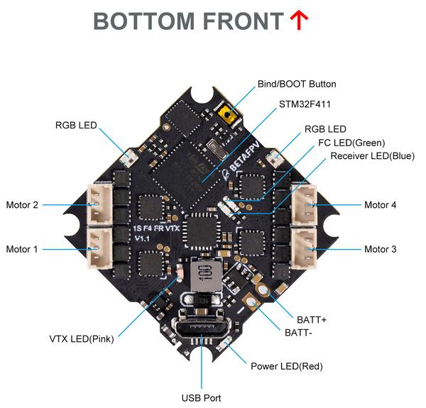
- 4 Indicators: Receiver indicator (Blue)/Flight control status indicator (Green)/Flight control power indicator (Red)/VTX indicator (Pink)
Package contents
You will get the F4 1S AIO VTX flight controller with BT2.0 pigtail and linear VTX antenna preinstalled. Also a bunch of the screws and silicone rubber grommets.
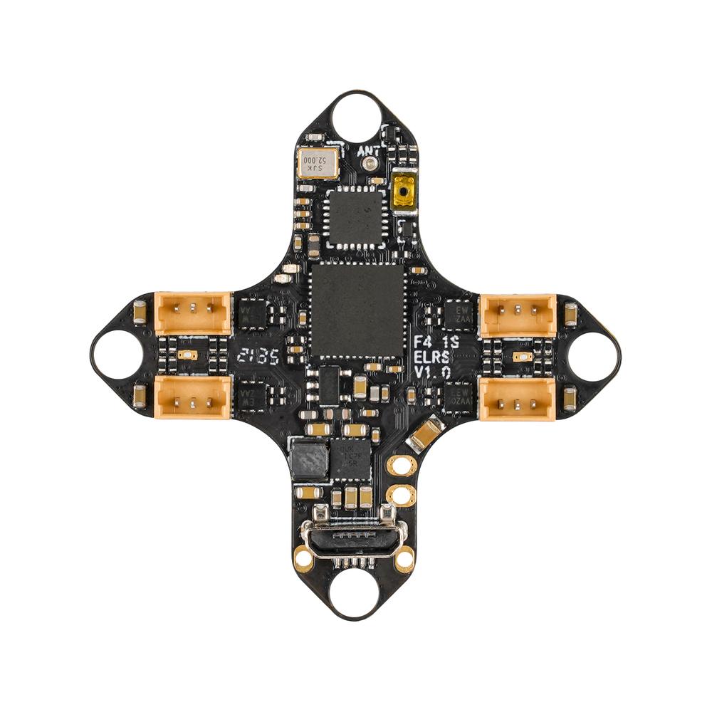
BetFPV F4 1S VTX AIO
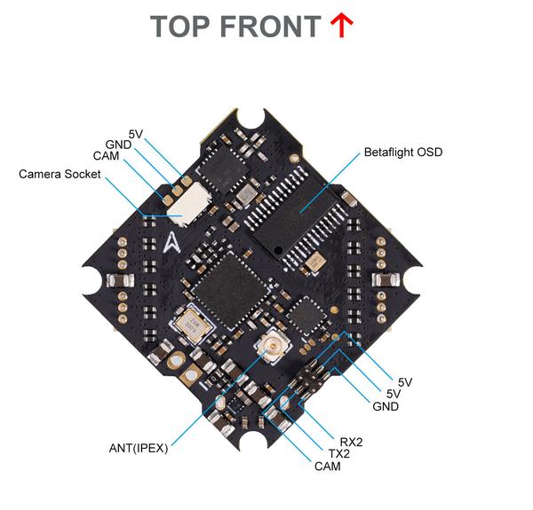
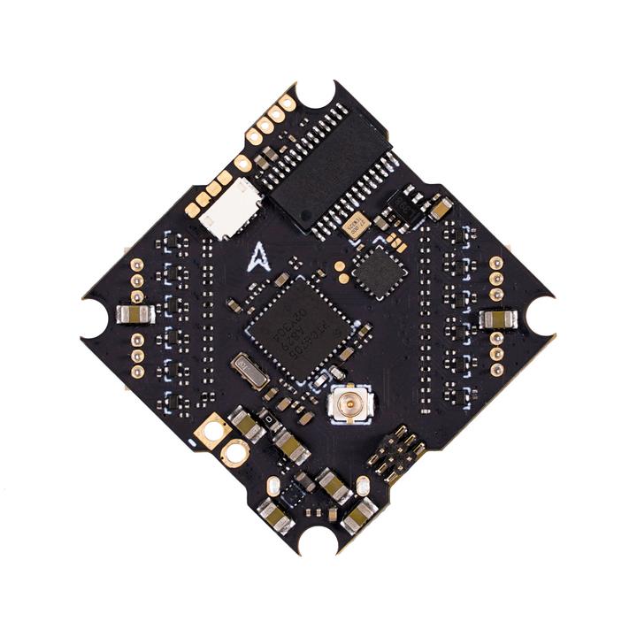
You can find the RTC6705 VTX, CC2500 SPI Receiver and OSD chips on the board. There is simple wire receiver antenna and the IPX (u.fl) antenna connector. There are only 3 solder pads for the camera (+5V, GND, CAM) on the top side of the board. This shows the plug and play nature of this FC.
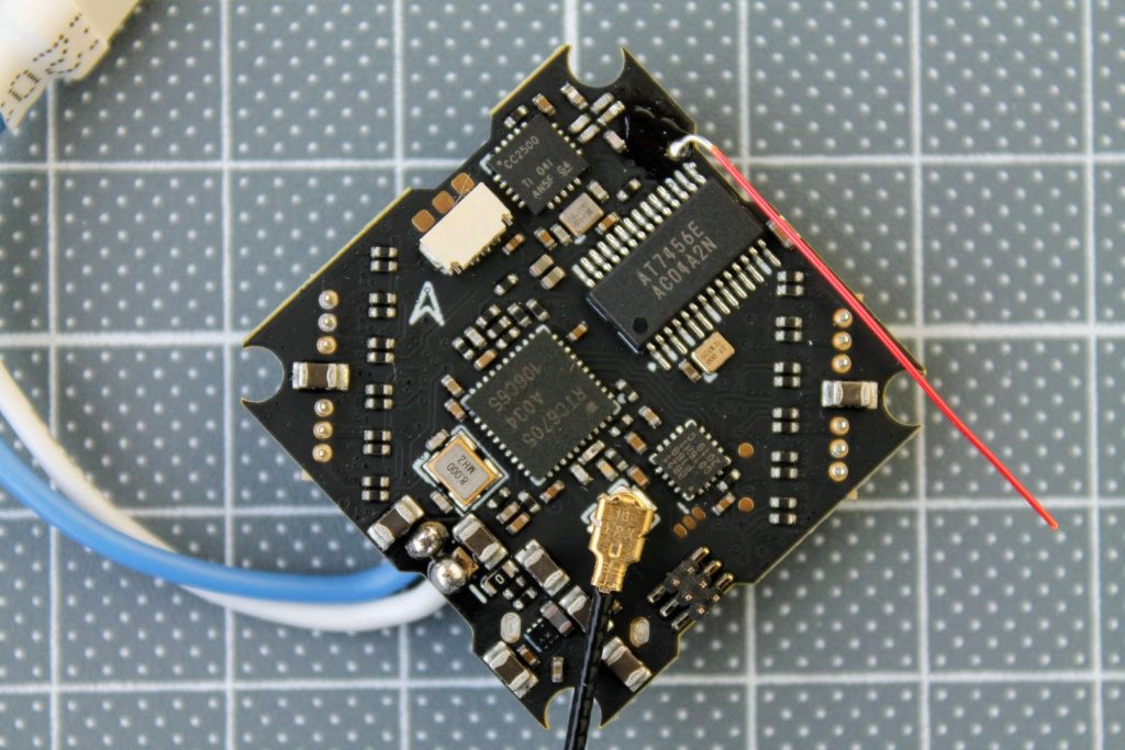
On the bottom side, near the top of the board, you can find the SE2431L chip. It is Low Noise Amplifier (LNA) by Skyworks, and is responsible for amplifying the receiving control signal. This means the built in receiver range is better than for instance on Happymodel CrazybeeF4.
The board comes with already pre-soldered BT2.0 battery pigtail and the u.fl VTX linear antenna.
Flight controller has socket for plugging the camera with JST0.8 connector. The compatible cameras with the preinstalled JST0.8 connectors are Co1 and C01 Pro cameras.
There is also a 6 pin header on the flight controller for connecting the BETAFPV Nano HD Camera (a tiny whoop variant of the Caddx Baby Turtle).
This makes the FPV camera and HD FPV cameras plug and play compatible with this flight controller. No need for soldering!
This board allows to build the whoop without the need of any soldering. All you need to build a whoop/toothpick is already on the board – just plug in the motors and C01 or C01 Pro camera. An you are done!
The weight of the flight controller with BT2.0 pigtail and the VTX antenna is 5.4 g.
Comparison with the Happymodel CrazybeeF4 FR V3.0 board.
BetaFPV F4 1S FR VTX AIO flight controller with integrated SPI Frsky receiver pinout:
There is a BetaFPV F4 1S VTX AIO flight controller without integrated receiver.
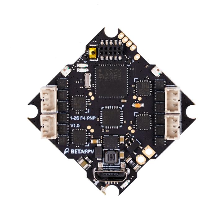
It has additional solder pads for external receiver and the additional socket for direct plug and play BetaFPV FR SPI receiver module.
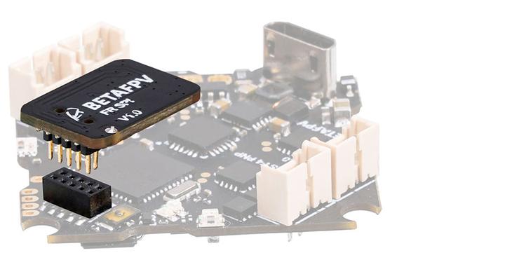
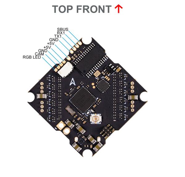
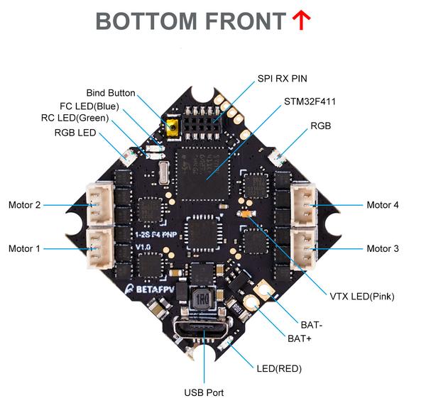
Pinout of the BetaFPV F4 1S VTX AIO flight controller without integrated receiver:
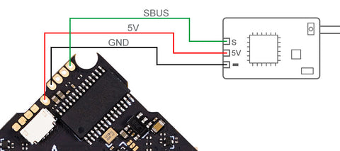
Connection diagram with the Frsky XM+, FS-RX2A and Futaba-X-BOSS AC900 external receiver.
Here is the connection diagram with the TBS Crossfire receiver.
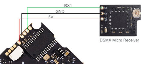
Here is the connection diagram with DSMX FullSpeed receiver.
Binding
In order to bind the SPI receiver you can use any of these three methods:
- Power the flight controller and then press the BIND/Boot button. The binding process will start.
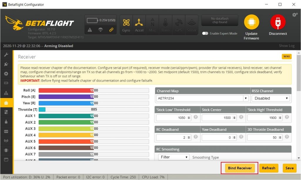
- Connect the flight controller to the Betaflight Configurator, select the Receiver tab and press the [Bind Receiver] button. The binding process will start.
- Connect the flight controller to the Betaflight Configurator, select the CLI tab, in the command line write the
bind_rxcommand. The binding process will start.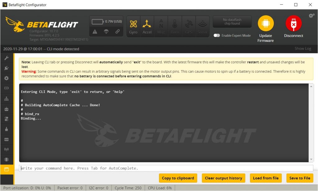
Available @ BetaFPV: https://betafpv.com/products/f4-1s-aio-brushless-flight-controller
]]>