All flight controllers, that run Betaflight, Emufligh,?Cleanflight?or other flight software, are based on the STM32 type microcontroller or MCU?(also can be called as “processor“).?STM32?is a family of 32-bit?microcontroller?integrated circuits?by?STMicroelectronics.?The STM32 family consists of series of?microcontrollers: H7, F7, F4, G4,?F3, F2, F1, F0,...?Internally, each microcontroller consists of the processor core,?static RAM,?flash?memory, debugging interface, and various peripherals. It is the main processing device of the flight controller. It runs the dedicated program called firmware (e.g. Betaflight) and controls the quad by sensing an measuring the environment by the help of external sensing devices – gyroscopes, accelerometers, compasses, barometers and GPS.
The main differences between the STM32 microcontroller series are: internal architecture, clock speed, internal flash size, number of interfaces for peripherals and other.
| Code | Core | Max freq [MHz] | Max FLASH [KB] | Max SRAM [KB] | Target |
|---|---|---|---|---|---|
| H7 | CortexM7 | 400 | 2048 | 1024 | High performance |
| F7 | CortexM7 | 216 | 2048 | 512 | High performance |
| F4 | CortexM4 | 180 | 2048 | 384 | High performance |
| G4 | CortexM4 | 170 | 512 | 128 | High performance |
| F2 | CortexM3 | 120 | 1024 | 128 | High performance |
| L4 | CortexM4 | 80 | 1024 | 320 | Low power |
| F1 | CortexM3 | 72 | 1024 | 96 | Mainstream |
| F3 | CortexM4 | 72 | 512 | 80 | Mainstream |
| F0 | CortexM0 | 48 | 256 | 32 | Mainstream |
F1
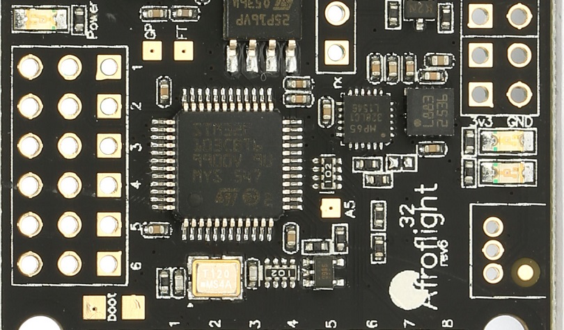
F1 series of the MCU were released in 2007.?This is the MCU that started the flight controllers era. NAZE32?was the first flight controller, based on STMF103 and Baseflight firmware. The most commonly used MCU was?STM32F103CBT6 with 128Kb of the flash space for firmware. This MCU currently is outdated as?Betaflight support for F1 MCU was discontinued in 2017. The last version that supports F1 is Betaflight 3.2 .
F3
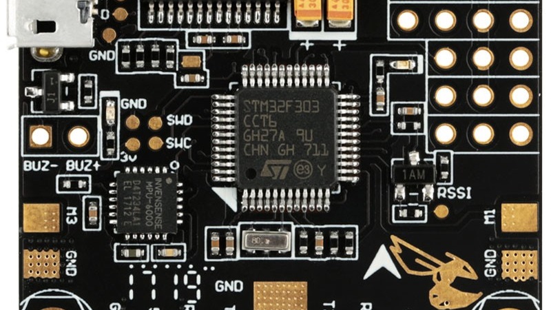
F3 series of the MCU were released in 2012. They have up to 72MHz core speed and up to 256 Kb general flash size.?The F3 is almost pin-to-pin compatible with the STM32 F1-series. Higher clock speed allows to run 2x higher loop times than earlier generation of F1 microcontrollers, up to 8KHz. F3 microcontrollers have 3 serial ports for peripherals.
This MCU currently is outdated as?Betaflight support for F3?MCU was discontinued in 2017. The last version that supports F3 is Betaflight 4.0. Read about this?here.
F4
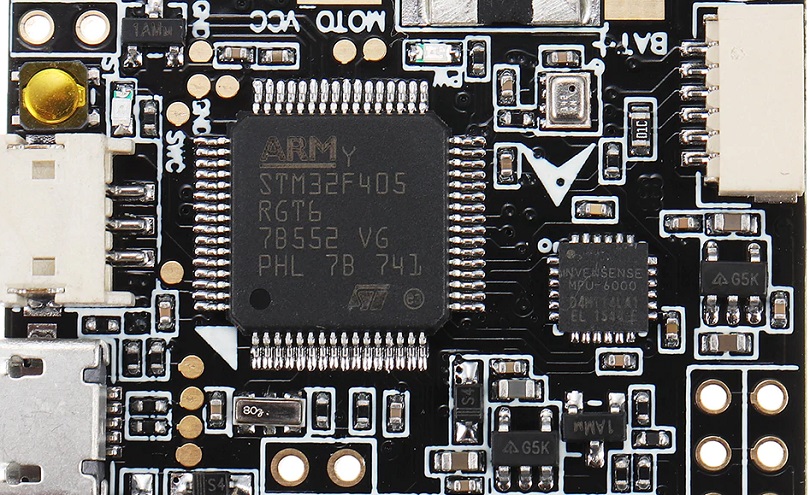
F4?series of the MCU were released in 2011. So the F4 MCU in fact was released before the?F3. They have marginally faster clock speeds, that enable to run up to 32KHz loop times.?Most popular F4 MCU are?STM32F405RGT6 with 168Mhz and?STM32F411CCU6 with 100MHz clock speed, but with reduced footprint size for smaller boards.
G4
STM32 G4 series MCU is released first in 2019. G4 is featured with extensive analog signal processing and rich advanced analog peripherals, has up to 512Kb of flash and up to 128Kb RAM memory, runs on up to 170MHz speeds. G4 provides better power efficiency and performance compared to the older F3/F4 series. G4 has 5 hardware UARTS.
First flight controller with STM32G4 MCU is FETtec KISS G4 flight controller, released in 2021-10.
[Picture pending]
F7
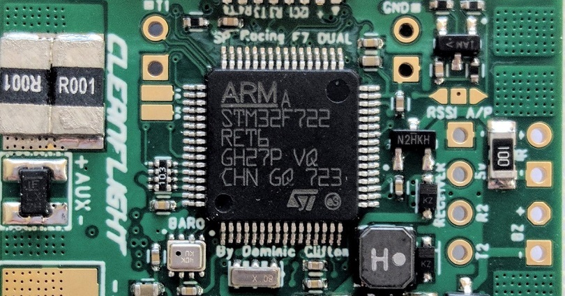
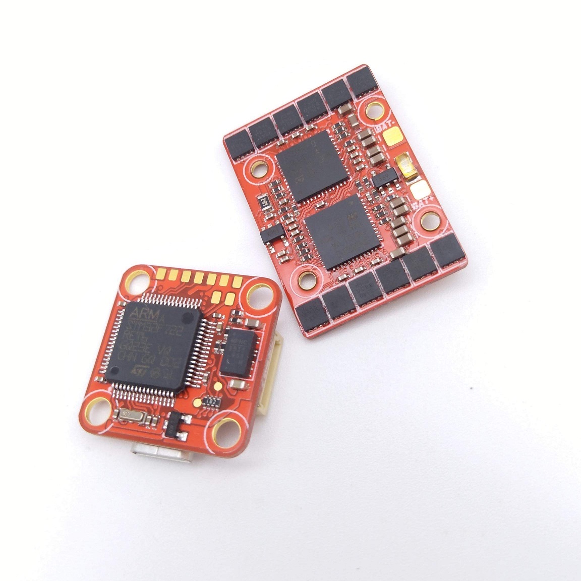
F7 series of the MCU were released in 2014. They have up to 216MHz?core speed and up to 2048Kb general flash size. The F7 is?pin-to-pin compatible?with the STM32 F4-series. The most popular MCU is?STM32F722RET6 has 512Kb?of flash memory, 128Kb or RAM and 5 hardware UARTS.
H7
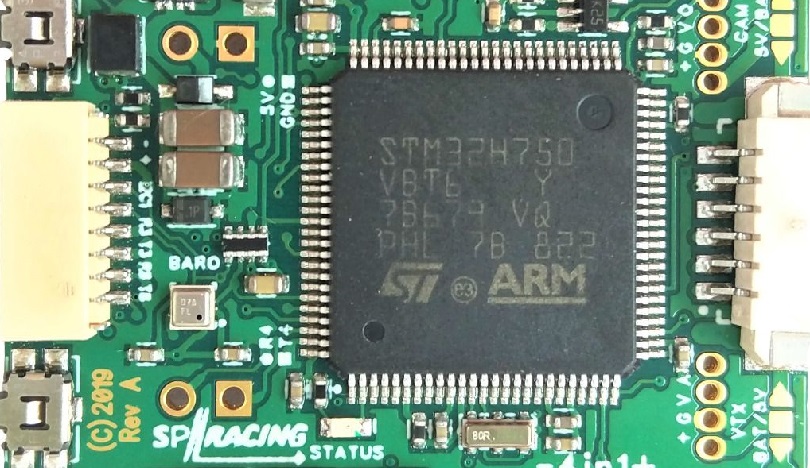
H7 is the newest MCU, released in 2017. It was designed as faster and more cost effective alternative to F7 series. Clock speed was almost doubled up to 400MHz. thanks to improved semiconductor manufacturing process from 90nm down to 40nm. This also reduces power consumption. H7 series are cheaper than F7 series, due to reduced internal flash size (using cheap external memory instead).
Inverted/uninverted serial ports
F3, F7 and H7?series microcontrollers have built-in ability to invert the serial signal. Other MCU’s – F1 and F4 have no build-in inverters, so either you need to invert SBUS and S.Port signals by external inverters or the flight controller manufacturer has to implement the additional inverting components on the FC board.
[To be continued]
2019-04-05 Article created
2021-10-05 G4 MCU introduced.
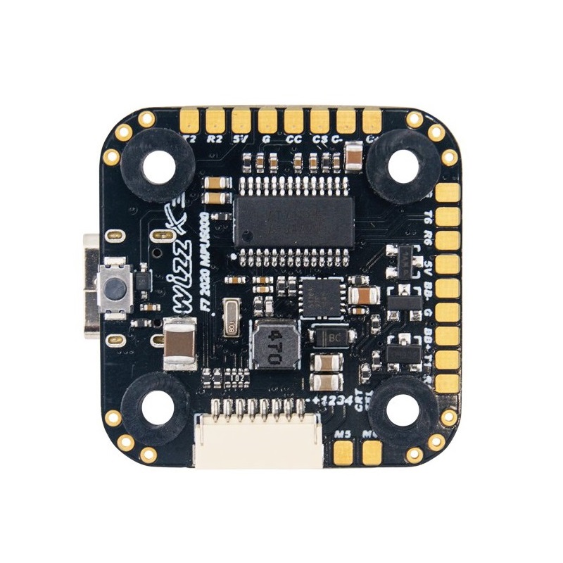
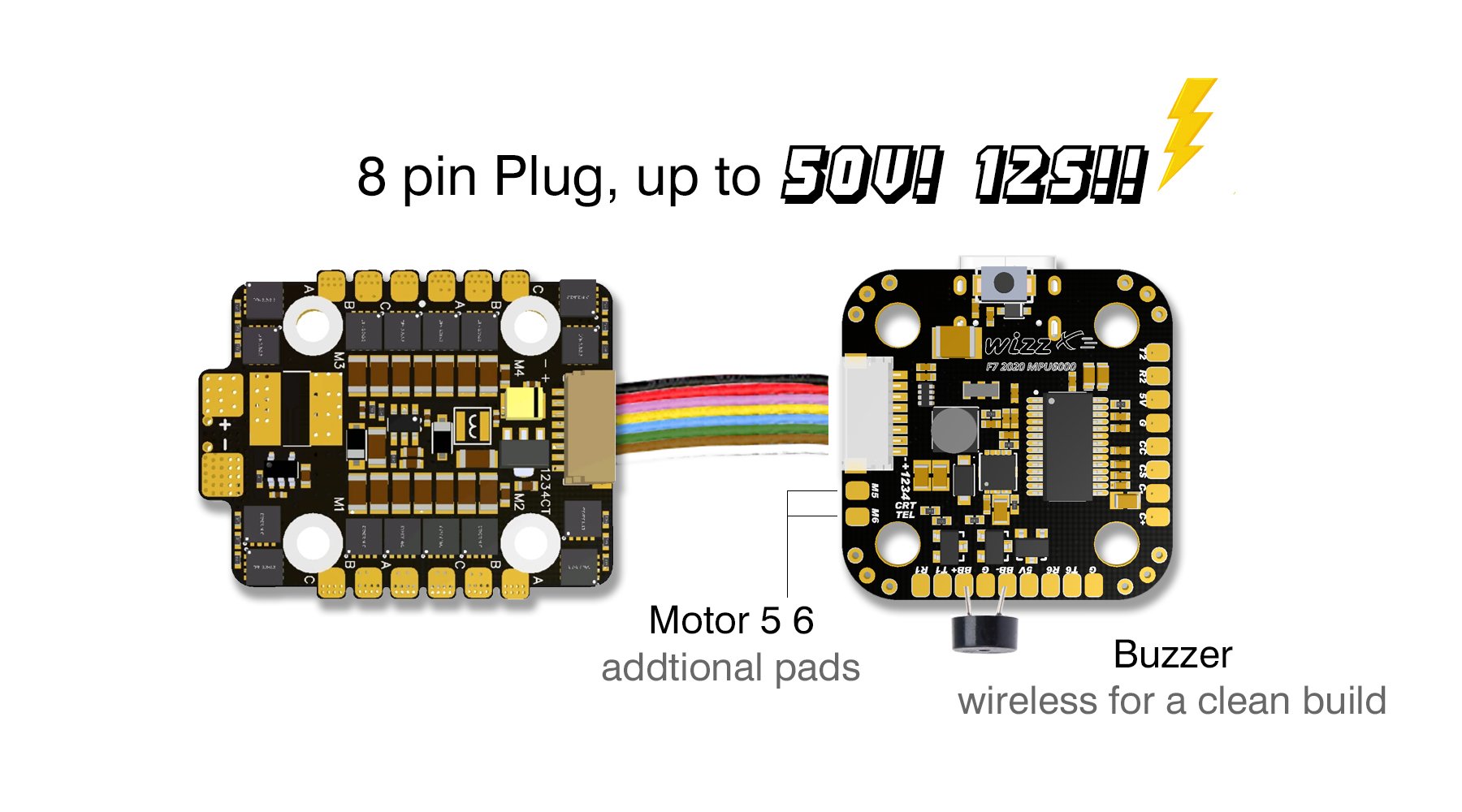
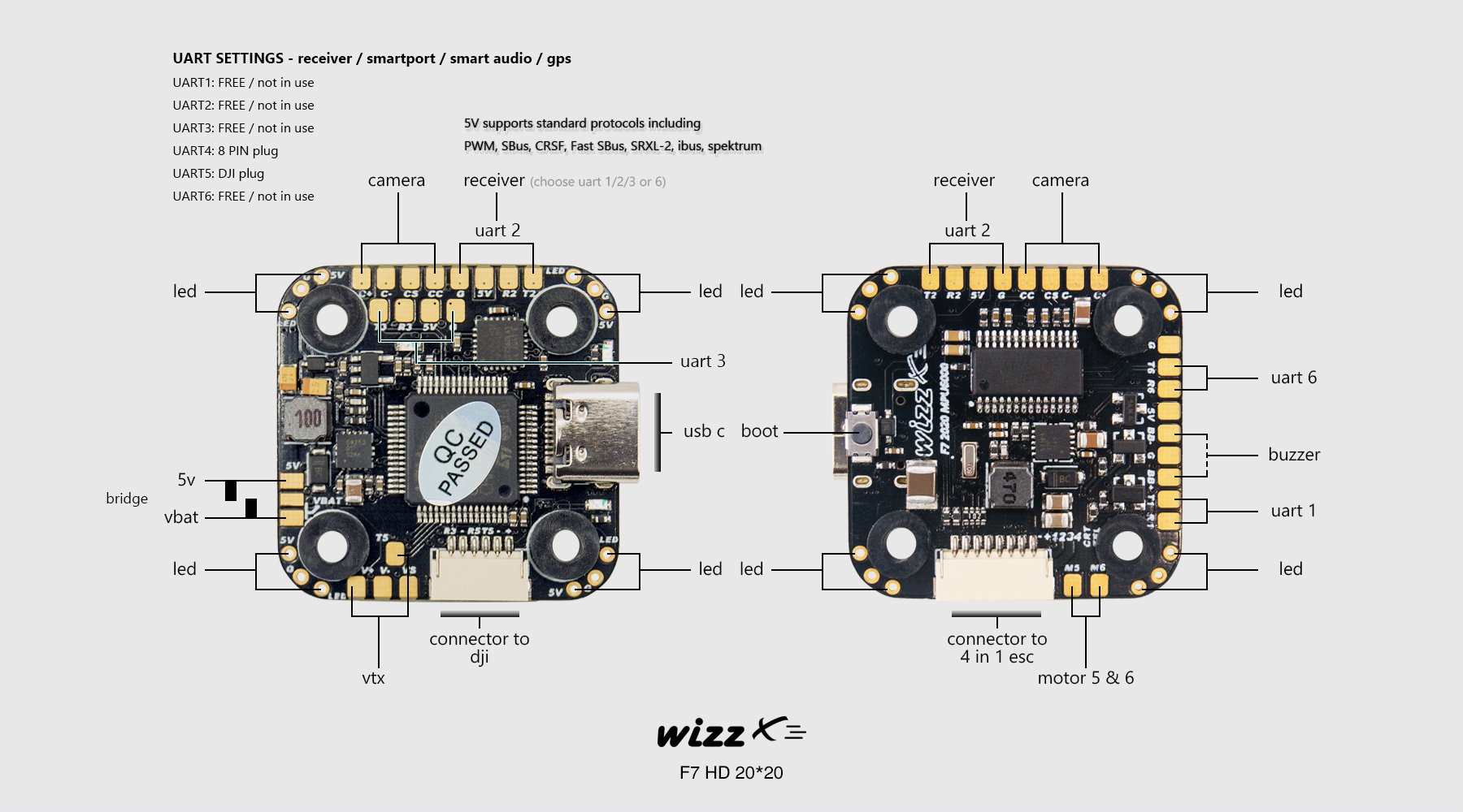
Wizz F7 FC?has 6 UARTS, M5?and M6 pads, VTX pit control, analog camera control and USB Type-C socket.
 |
 |
FC supports up to 12S (50V) direct input.
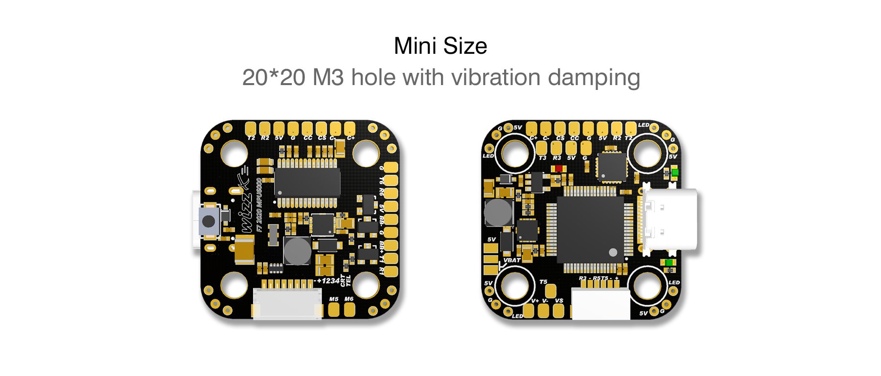
Fits the mini sized 20x20mm stack.
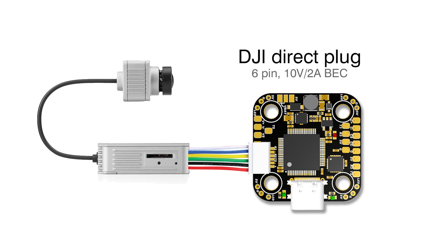
Has digital DJI Ai unit socket for direct connection.
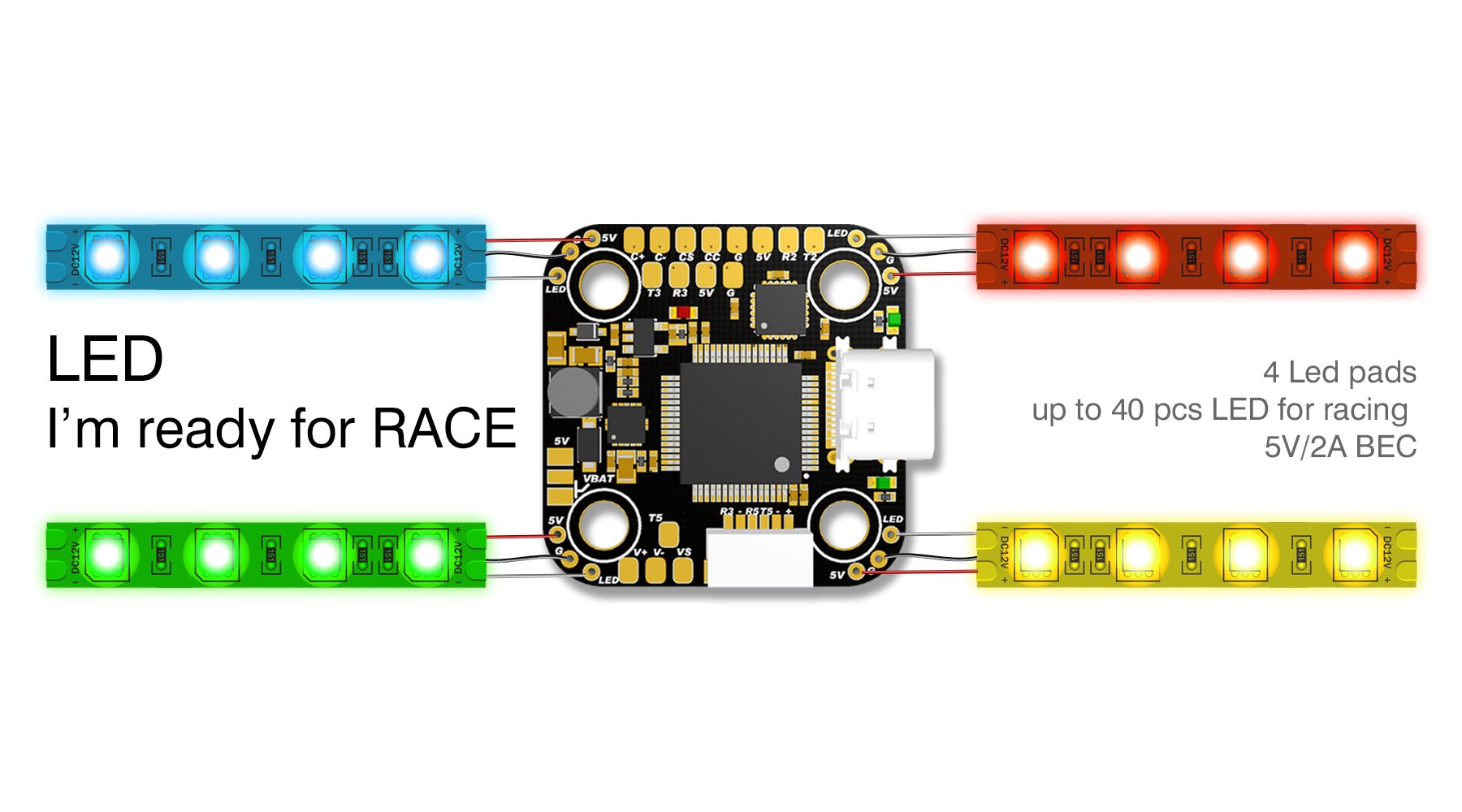
Wizz F7 FC has 4 LED pads on every corner for easy wiring the led strips.
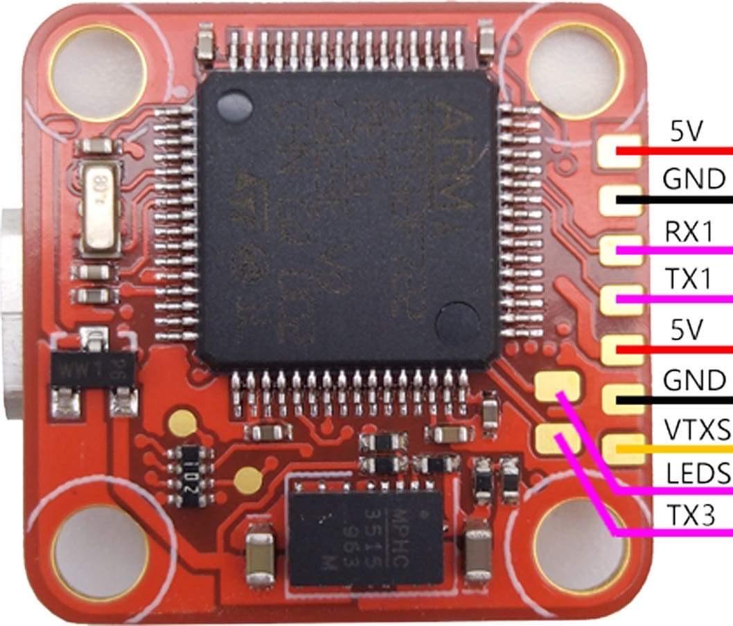
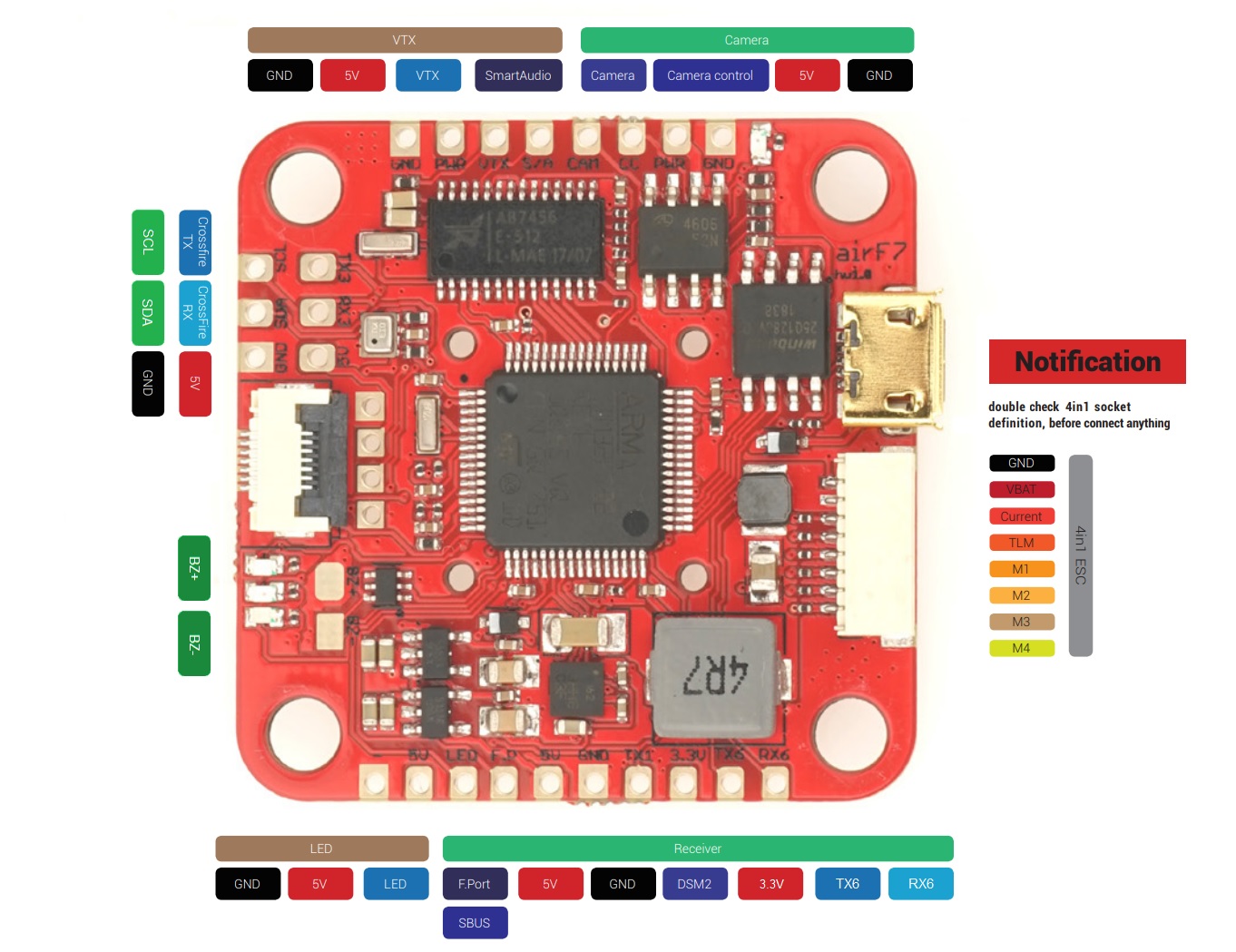
Wizz F7 FC pinout.
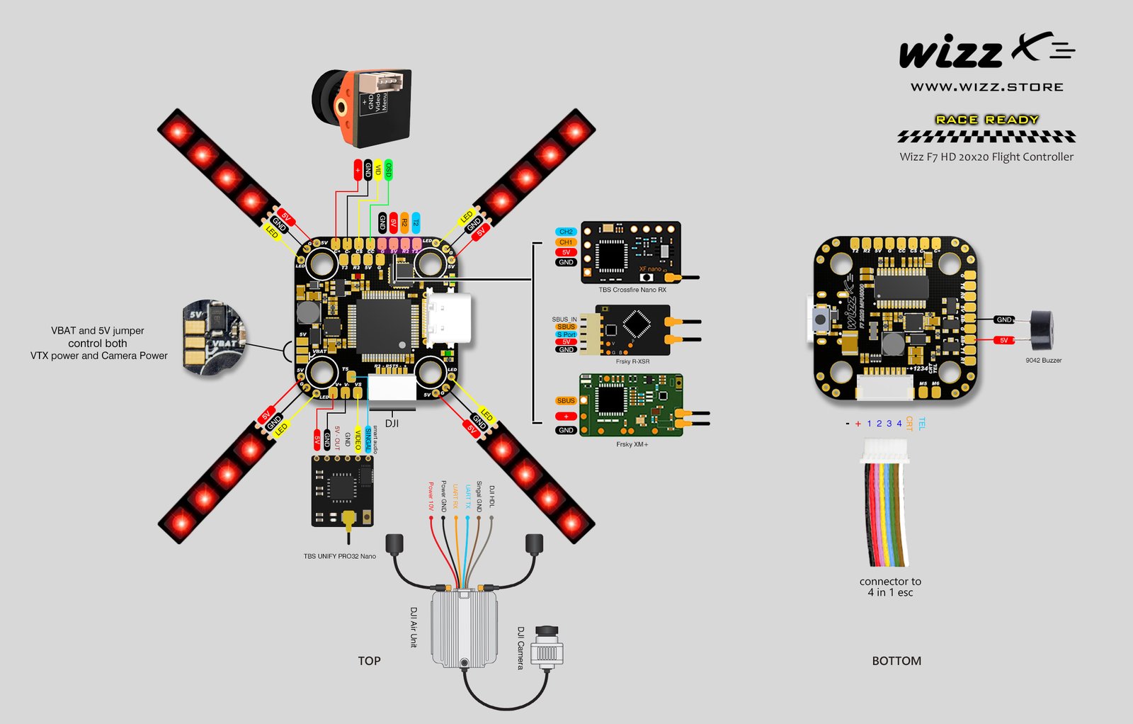
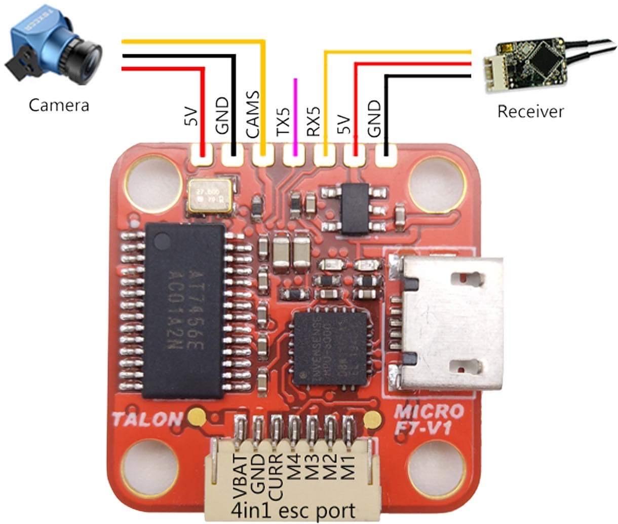
Wizz F7 FC connection diagram.
Available @
Wizz:?https://wizz.store/products/wizz-f7-hd-20×20-flight-controller
Specifications:
- Size: 20*20 M3 holes with vibration damping
- MCU: STM32F722RET6 216MHz
- Gyro: MPU6000 6-Axis
- Input: Up to 12S (50V) direct battery power Yes! 12S!
- USB type C
- DJI direct plug (6 pin)
- VTX pit mode switch – configured in Betaflight modes
- 5V or VBAT selectable for VTX and CAM power
- One wire Analogue Camera Control
- 4 Led pads (one at each corner) for easy LED installation – up to 40 LEDs on white and 100 LEDs in color – perfect for FAI international races – shares 5V with 5V/2A BEC
- 6 UARTS, 4 full UARTS with RX AND TX pins
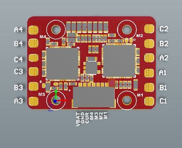
- 8 pin 4 in 1 ESC plug
- M5, M6 pads for additional motor outputs
- Buzzer pads for external buzzer
- Built in Betaflight OSD
- Boot button
- Logical pin layout for cleanest build
]]>
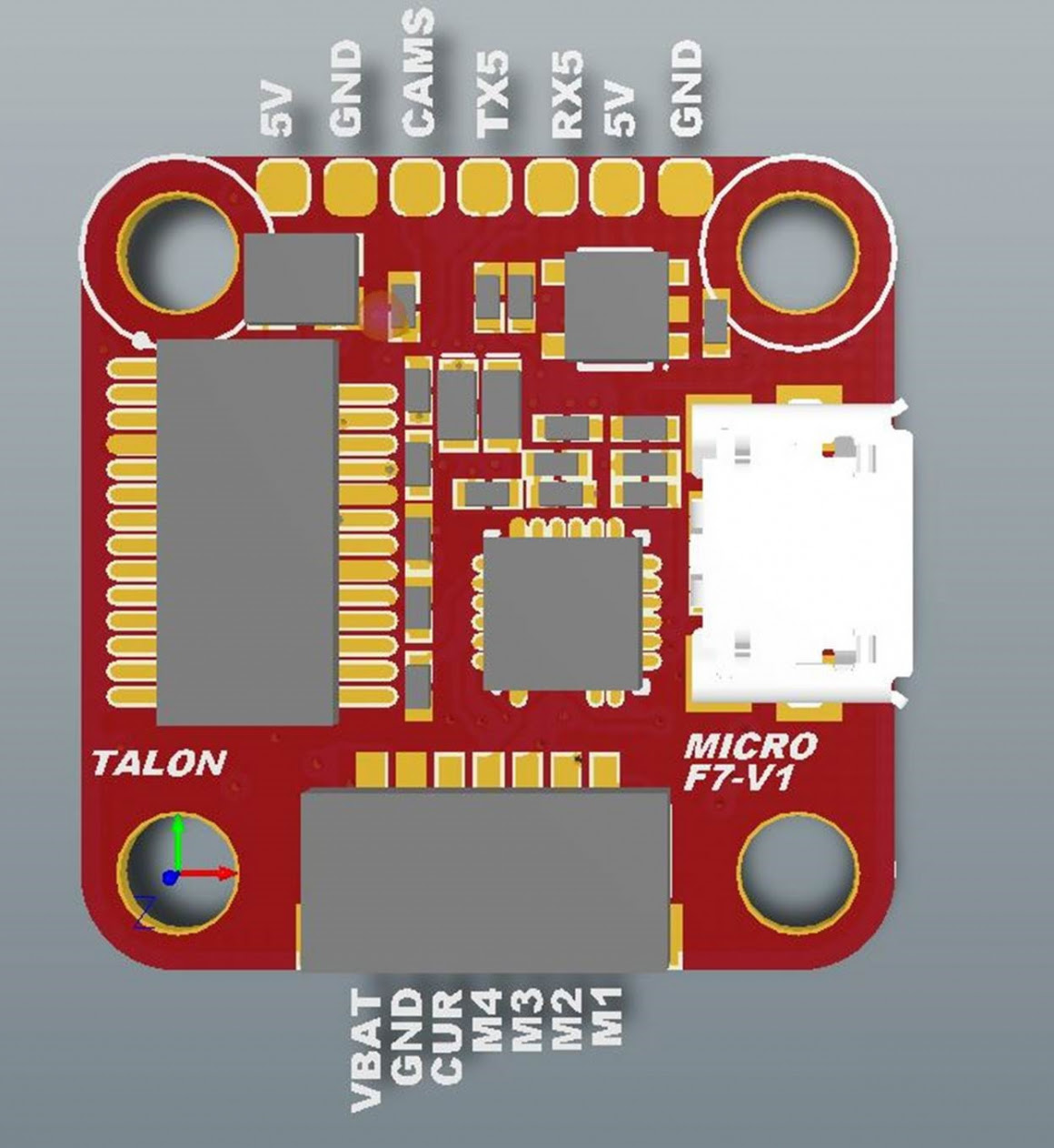
Stack package includes FC, 4in1 ESC, connecting cables, XT30 pigtail, capacitor and the rubber grommets.
Available @:
Heli-Nation: https://www.heli-nation.com/tiny-talon-16×16-f7-stack-blheli-32-esc
GetFPV: https://www.getfpv.com/heli-nation-tiny-talon-f7-micro-stack.html
Flight Controller specifications:
First micro (16X16) STACK with F7 and 32bit ESC
MCU: STM32F722RET6 216MHz
6-Axis MPU6000 gyro
Build in Beta flight OSD
2-4S( 17V ) direct battery power
Build in Voltage monitoring resistor
Build in 5V/1.5A BEC and 3.3V/250mA for system
2 free FULL UARTS: UART1, UART5
VTX use UART3 TX3. for VTX control
16×16 mounting pattern
Designed to use on 5V camera and VTX.
ESC specifications:
2-4s Battery Input.
First 16×16 mounting 32bit ESC, running BLHELI_32
15A continuous and 20A burst.
RPM filtering support
build in Current sensor
Specifications
Racerstar AirF7
Package contains the Racerstar AirF7 FC, silicone rubber grommets and 8-pin JST-SH 1.0mm cable for connecting 4in1 ESC board.
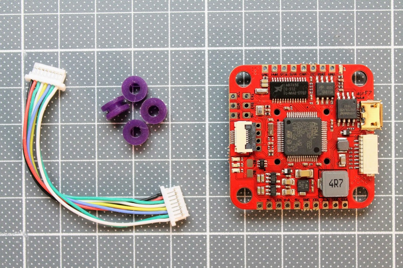
There is the user manual included in the package.
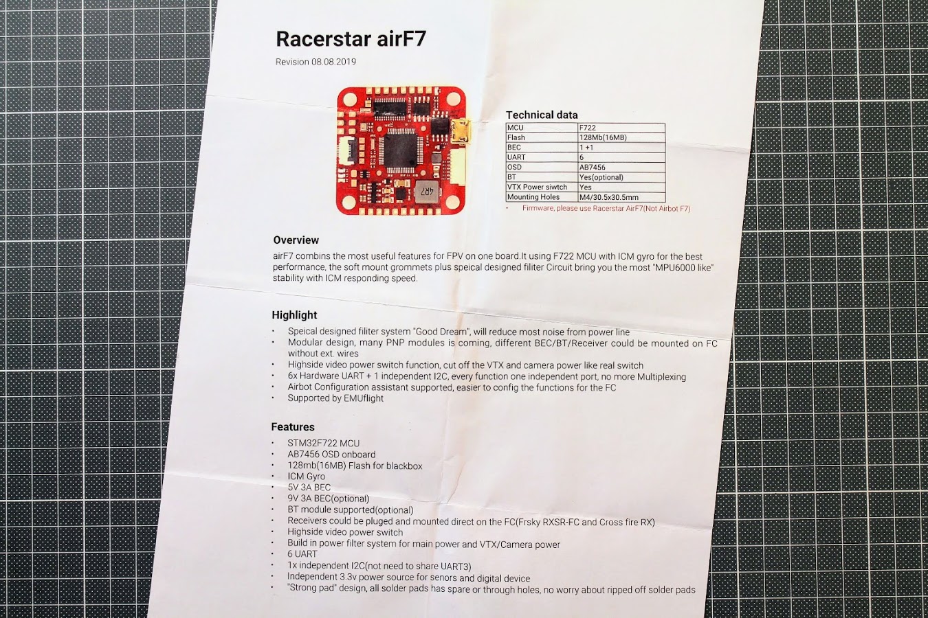
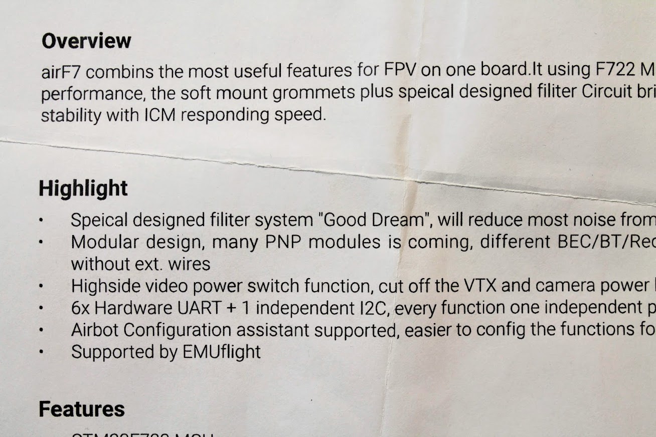
User manual is realy low quality, printed with some angle offset and with many spelling and grammar mistakes. I havent heared of such a thing as “Speical designed filiter system “Good Dream”” 
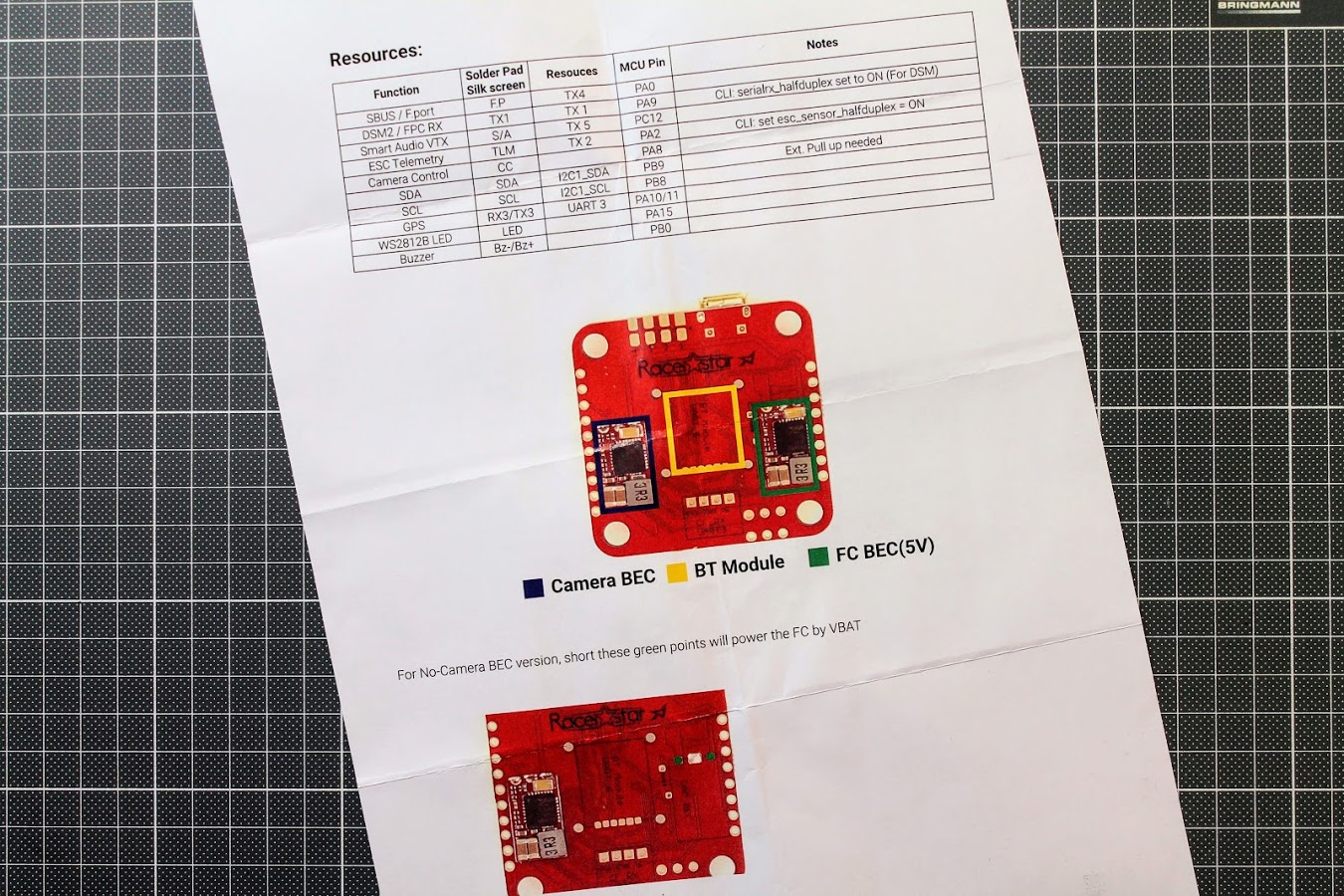
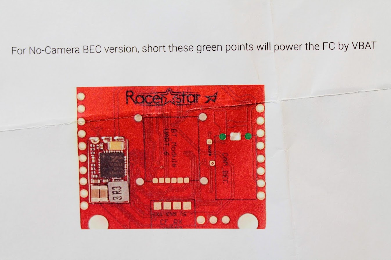
User Manual states that the BEC on the right is FC BEC (5V)
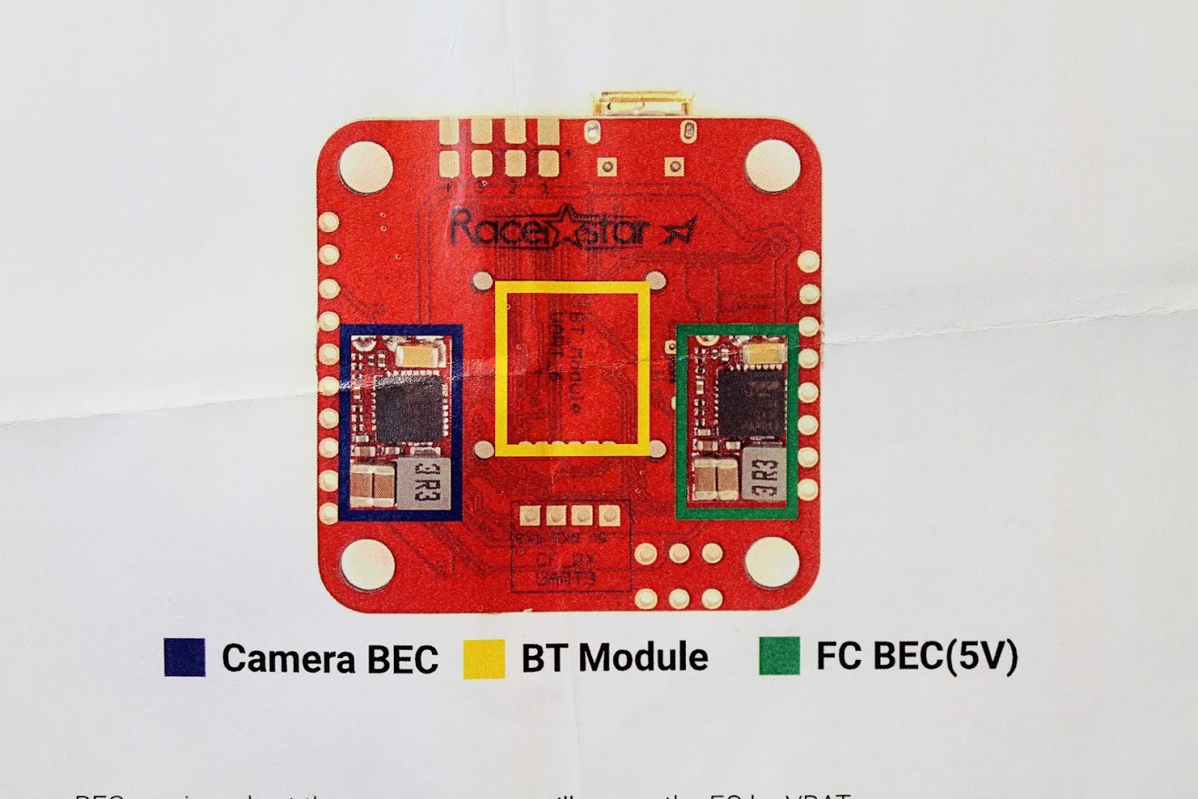
But in reality the right BEC is Camera BEC (9V). You can clearly see the markings CAM_BEC on the PCB:
Actually the AirF7 user manual is based on the Airbot F7 user manual, but Racerstar should have done it better.
Airbot F7 user manual: https://store.myairbot.com//media/iverve/uploadpdf/1561739006_80127-AirbotF7-0505.pdf
Racerstar AirF7 user manual: http://myosuploads3.banggood.com/products/20190909/20190909214037RacerstarairF7.pdf
Also AirF7 user manual has no pinout information, so I have copied the pinout scheme from the Airbot F7 and made the Racerstar AirF7 board pinout scheme.
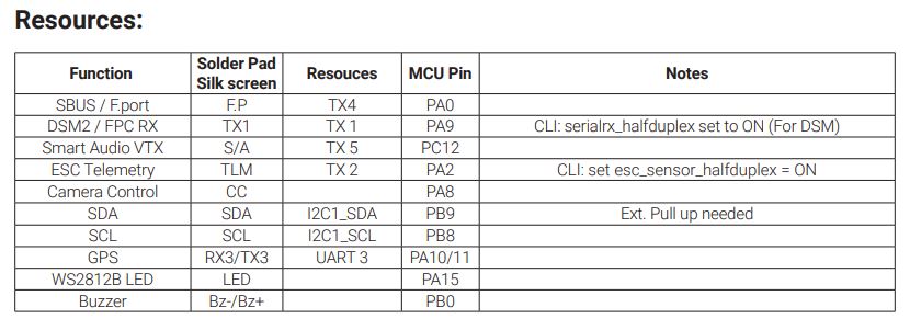
The resource table
Flight Controller in details
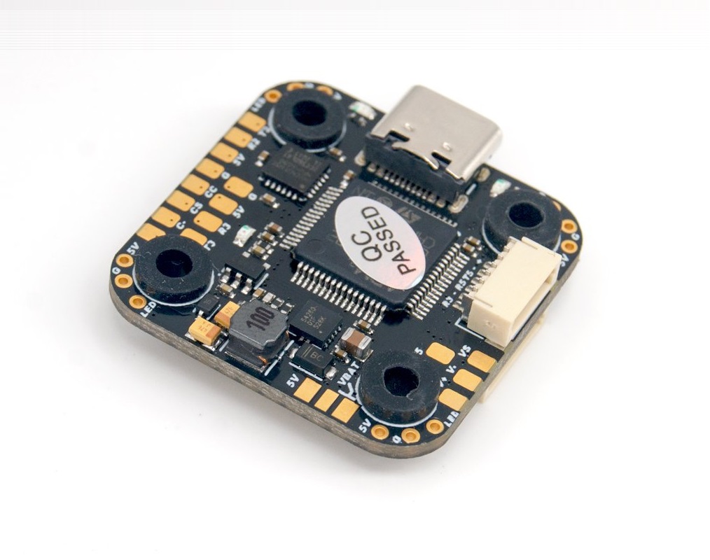
This AirF7 flight controller is stacked with features and surprises. Lets look at them.
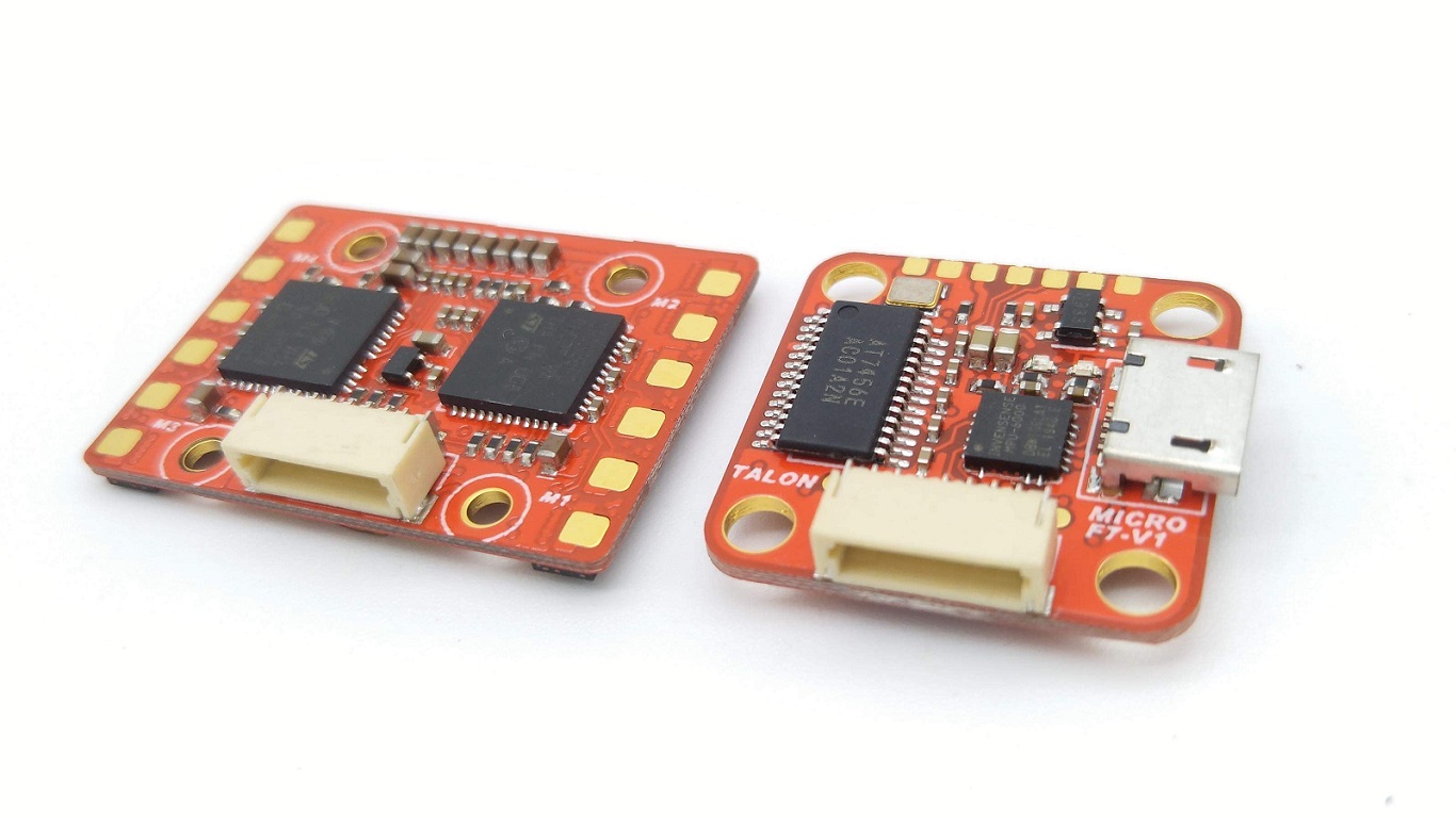
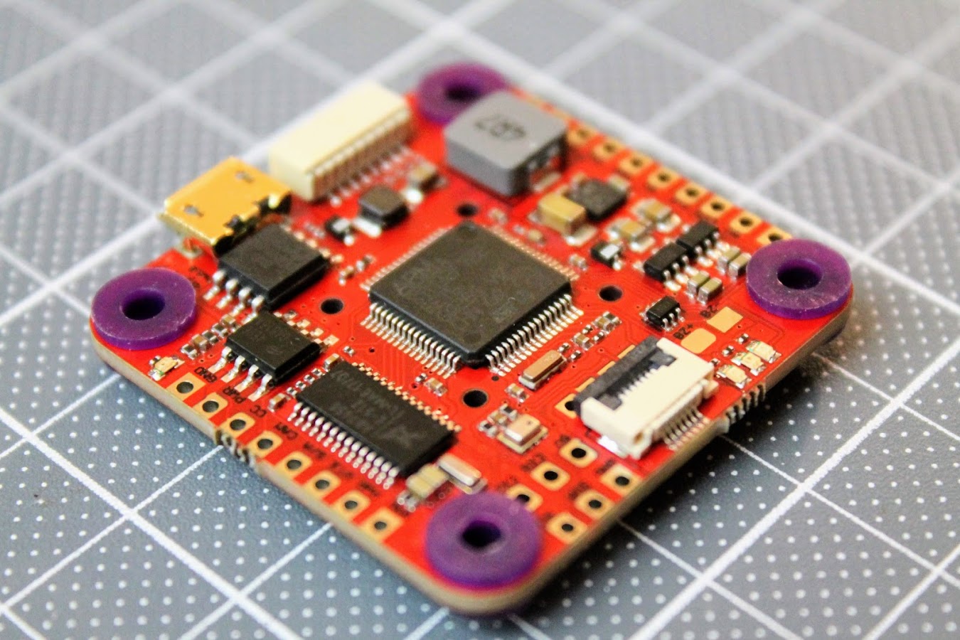
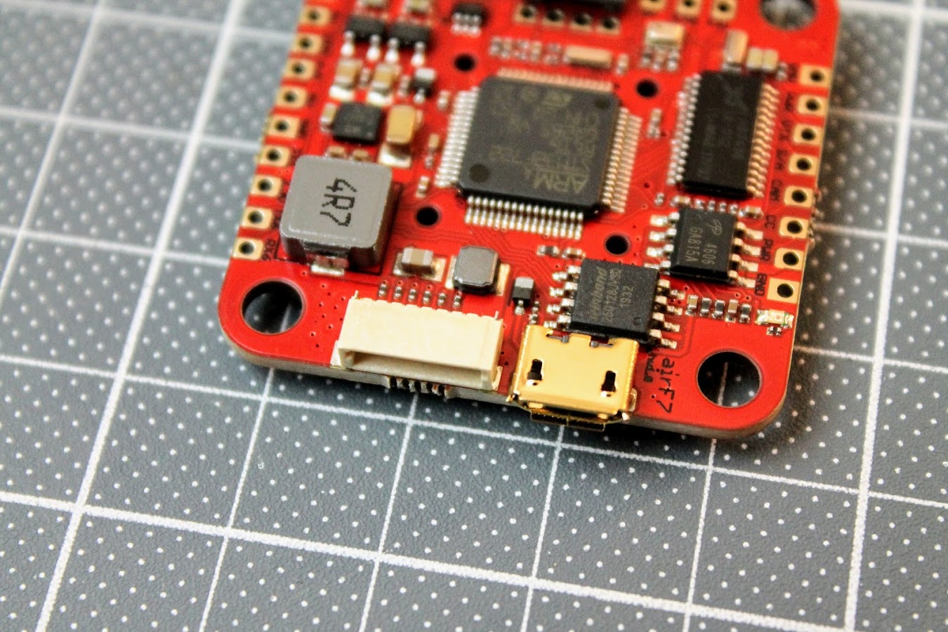
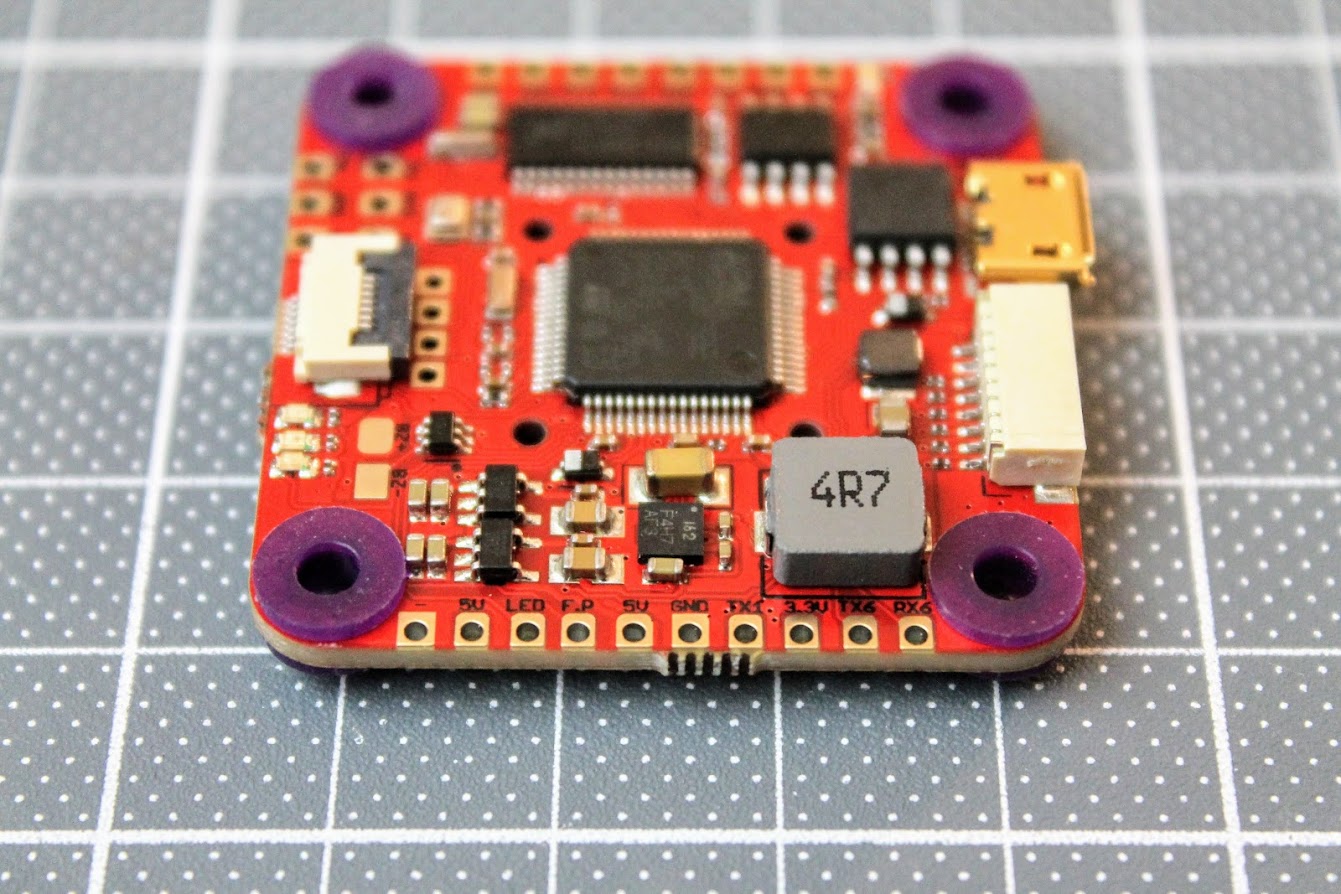
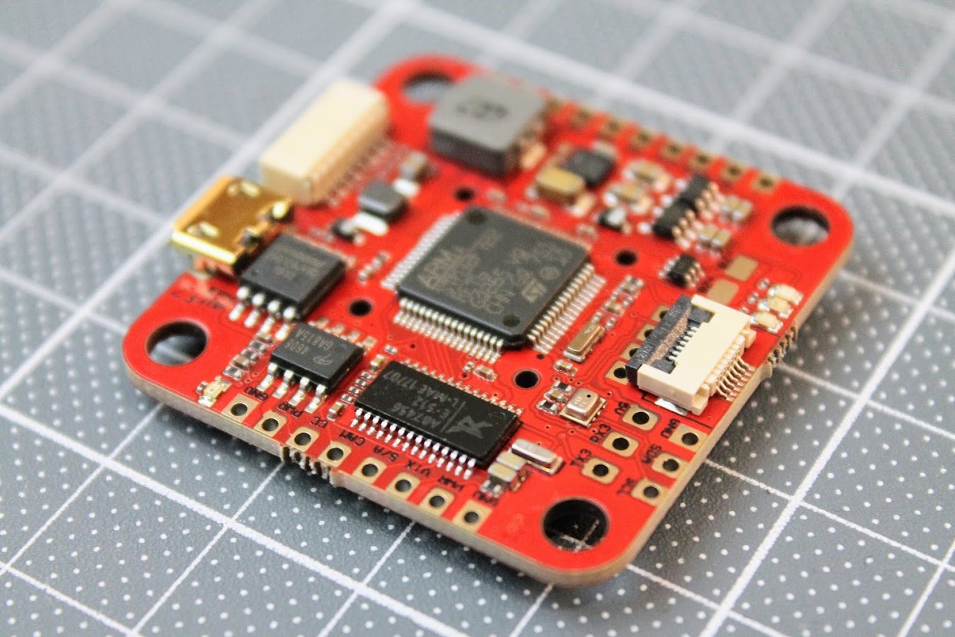
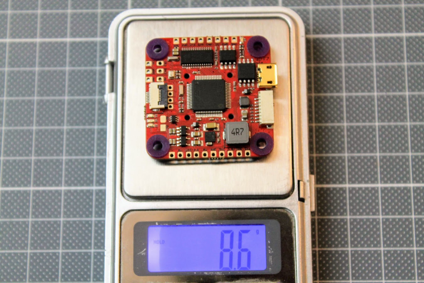
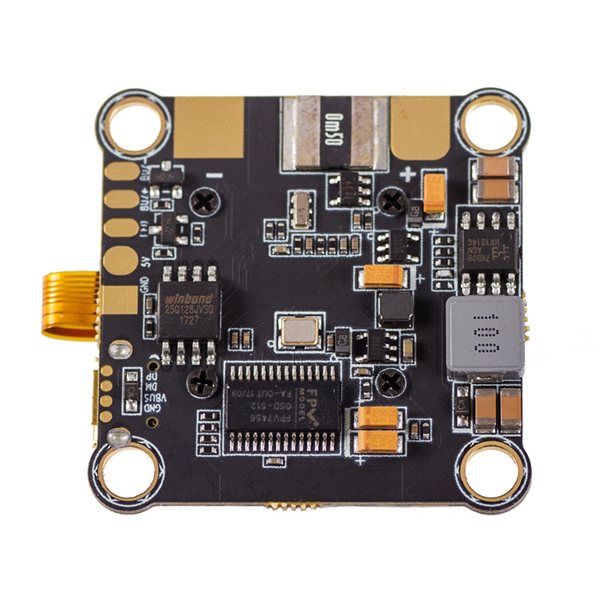
The view of the flight controller top side.
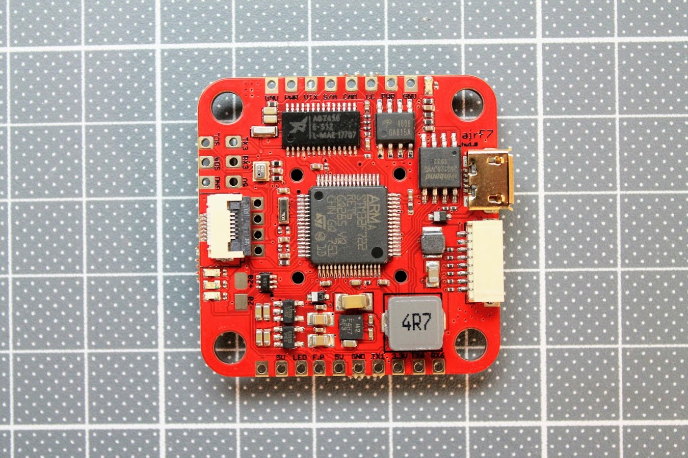
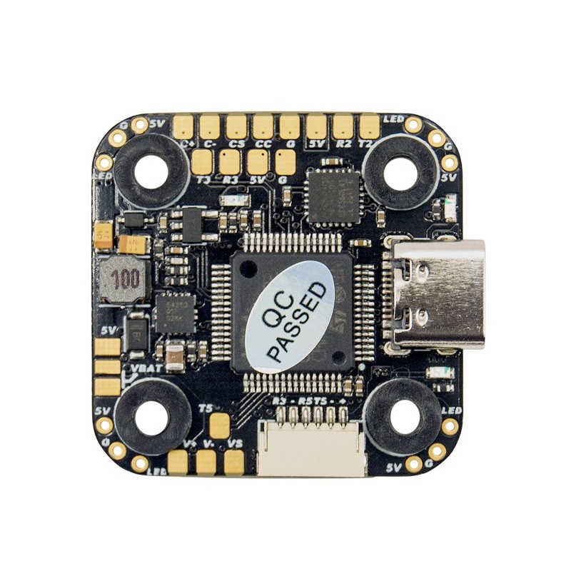
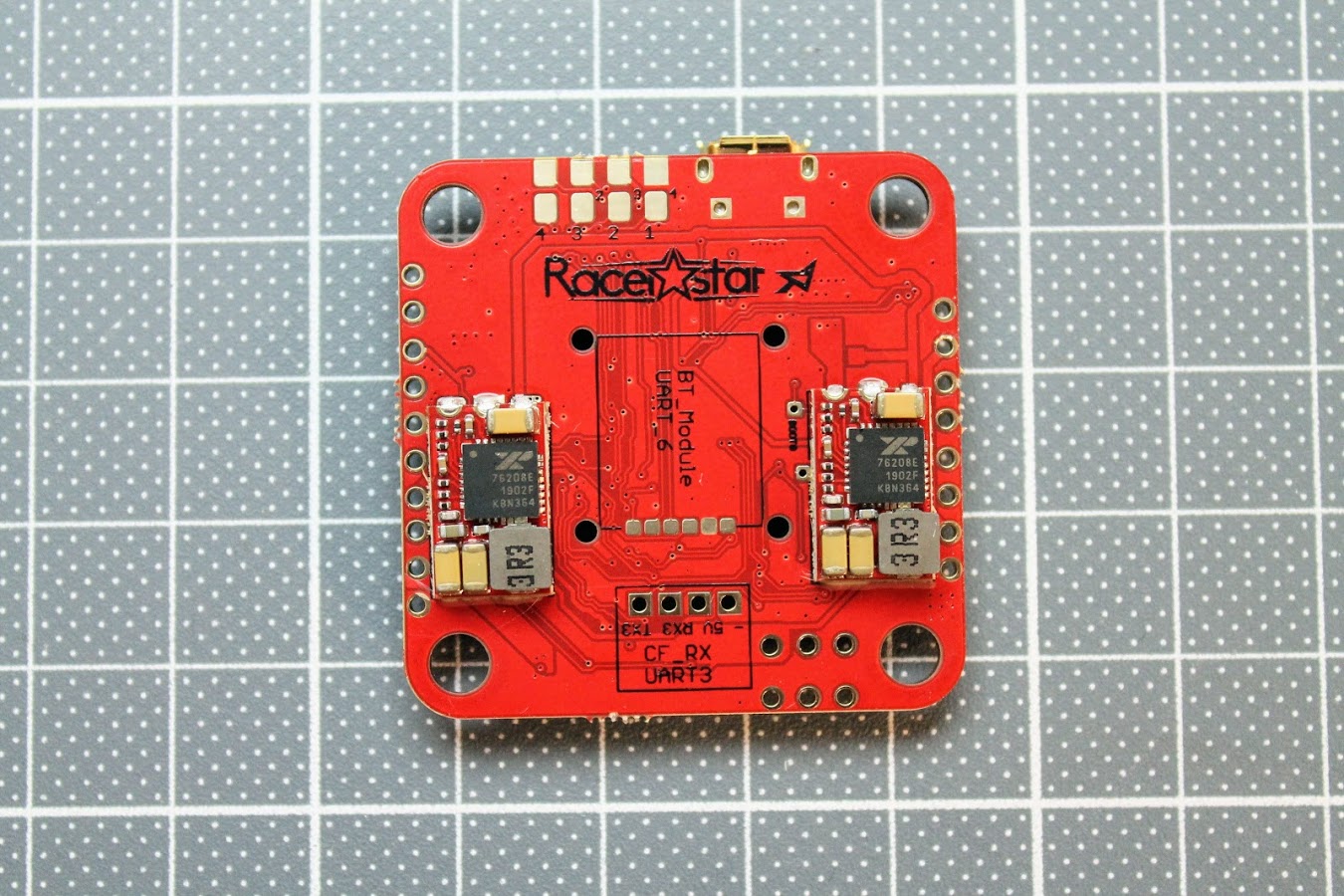
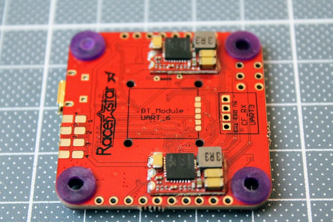
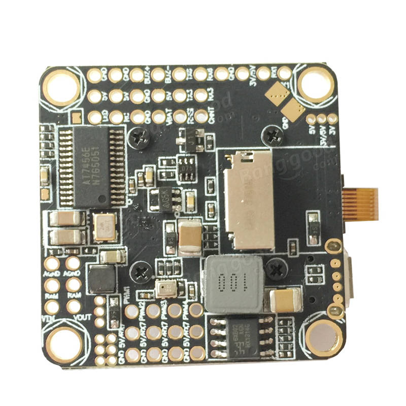
The view of the back side
There is micro USB and 8-pin JST-SH 1.0mm socket for connecting to the 4in1 ESC on the right side of the board. You can find the pinout of the socket in pinout scheme above. There is BlackBox Flash 16MB memory chip right behind the USB socket.
Whole row of the pads for LEDs and UART 6 pads on the bottom part of the board. GND, 5V and LED control pads for programmable LED strips and lights. F.Port (Inverted) , 5V, GND, TX1 (uninverted) and 3.3V pads for connecting various receivers that need inversion (SBUS, FPort) or doesn’t need it. Also free TX6 and RX6 pads for UART 6 are available.
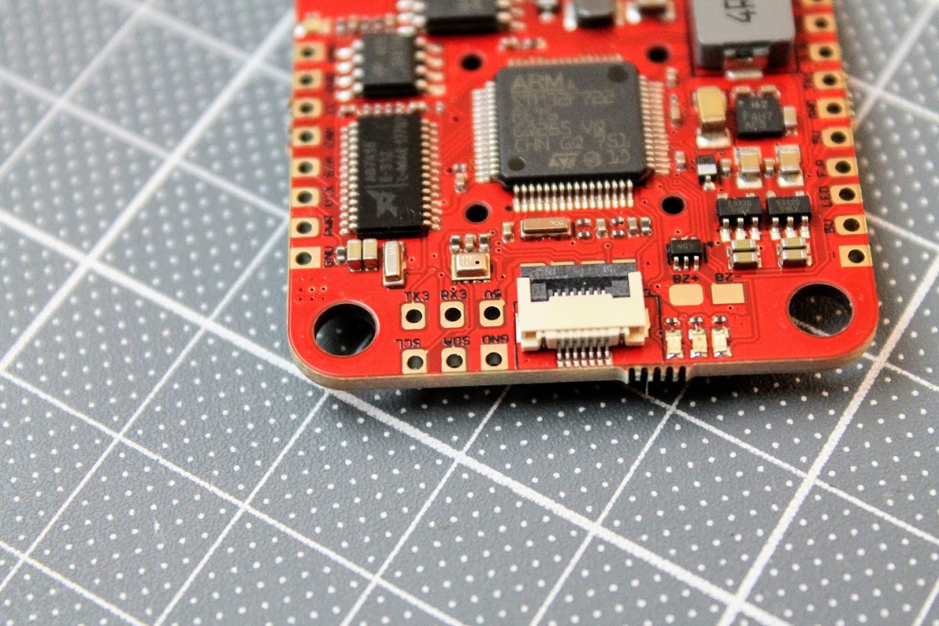
On the left side there are UART 3 pads and I2C interface pads. There is a undocumented Barometer on this FC, right behind the UART 3 pads! There are three status LEDs and buzzer pads. The connector in the middle is the SPI interface socket for connecting the External Gyro, R9MM-FC or RXSR-FC receivers.
On the top side of the board there are Camera GND, Power, Video and SmartAudio pads. Also VTX GND, Power , CameraControl and Video pads. You can see Airbot AB7456 OSD chip behind the Camera pads and AO4606 Mosfet VTX power switch behind the VTX pads. The Airbot AB7456 OSD chip uses less power, is tolerant of wider voltage swings and twice as much nvram than the commonly used MAX7456 chip. There is LED indicator besides the VTX pads to indicate the VTX power status. LED is off if the VTX power is swithed off (VTX PIT mode).
On the bottom side of the board there are GND, +5 and TX3, RX3 pads for direct soldering the Crosfire Nano or FrSky XM/XM+ receivers.
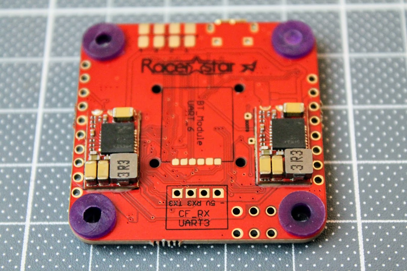
In the middle of the bottom side there is a place for soldering the optional Bluetooth module. It would use UART6 for the communication with
There are ESC solder pads in the normal and reversed order for soldering convenience.
There are Bootloader pads next to the 9V BEC, marked BOOT0.
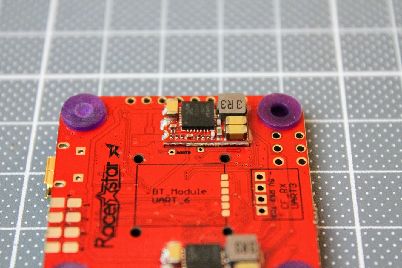
Weight of the board is 8.6 grams.
Configuration
Racerstar AirF7 Betaflight target is AIRF7 (RAST) and is available from Betaflight 4.1.0.
There are some notes in the product page regarding the firmware, but I think these are outdated now:
Because the firmware is provisional, for 9V BEC there have 2 steps to switch on :
1. Please type in CLI as:
RESOURCE SERIAL_RX 4 NONE
set pinio_box = 40,41,42,43
aux 2 40 2 1600 2100 0
resource PINIO 1 A10
save
2. Then use AUX 3, and the range must cover 1500
we don’t know if betaflight can put this setting in the released firmware, but if it’s happened the 9V BEC not working ,you know how to resource .
Actually the board comes with RealPIT feature preconfigured on AUX3 channel.
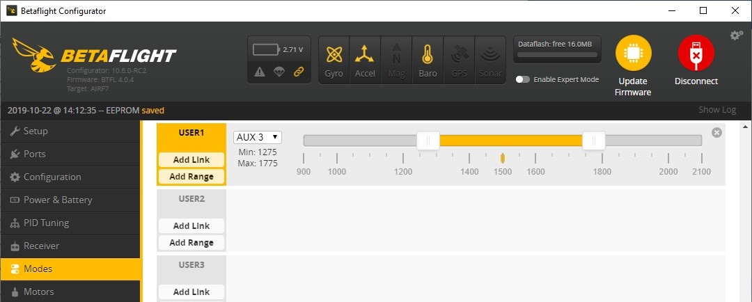
VTX power is switched on when AUX3 is in the range. You can adjust the range or AUX channel to your needs.
[To be continued]
Disclaimer: This item was supplied by Banggood for a fair and unbiased review. Banggood never asked for a positive review and never infuenced my opinion in any way. I’m trying my best to stay uninfluenced and give only my own opinion. All affiliate links if there are any help me purchase items for future reviews.
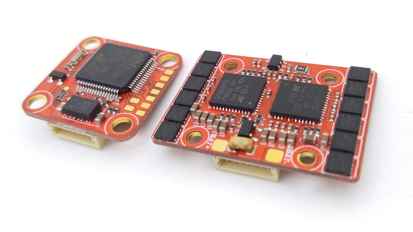
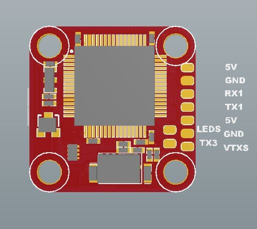
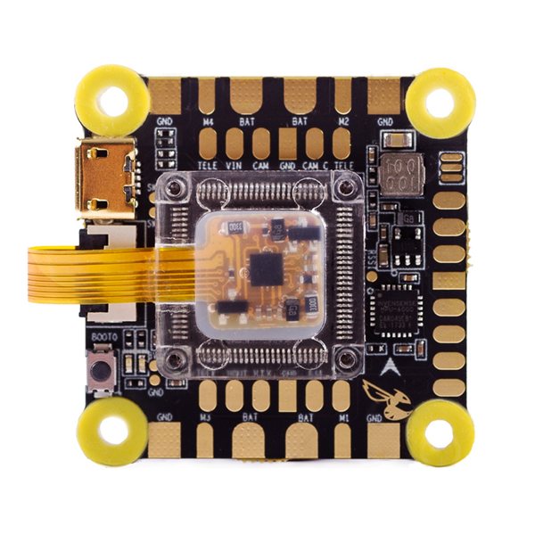
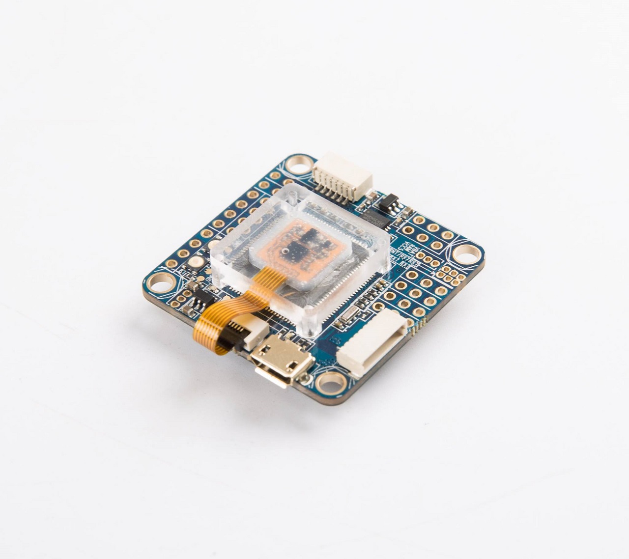
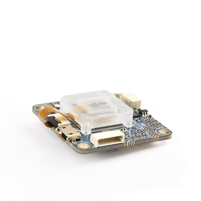
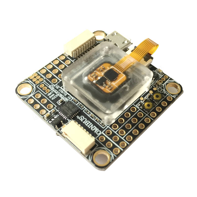
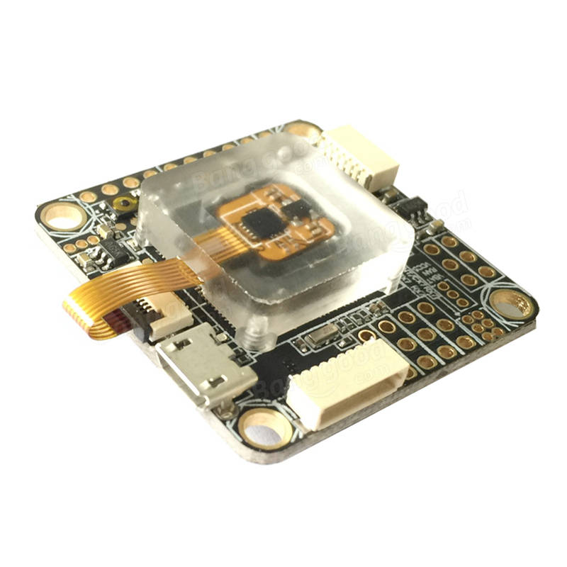
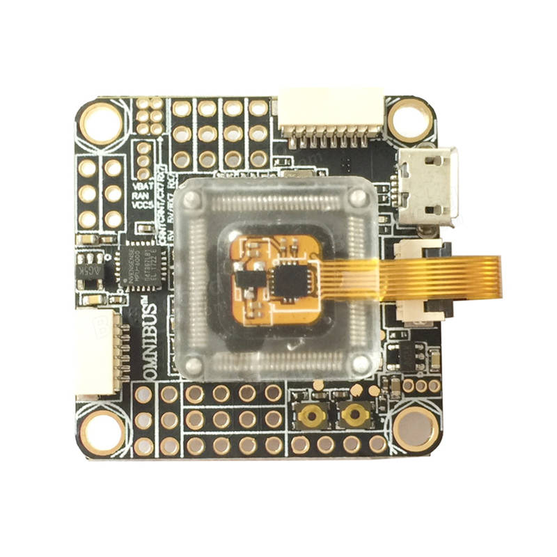
]]>The Betaflight F7 features dual gyros so the user can have their choice of which one to use, either the tried and true MPU6000 ( for sampling up to 8khz), or the ICM20608 ( for sampling up to 32khz). The later ICM20608 is encapsulated in the dampening jelly box and the whole FC has dampening grommets in the mount holes, so you can be sure that gyros are well protected from vibrations.
Specifications:
3-6s
Simplistic Layout
Two Gyro options
Betaflight OSD
Filtered output for FPV systems
Smart Audio/Tramp Telemetry compatibily
4 uarts (can read inverted and univerted signals)
Camera Control
Buzzer
Blackbox via flash memory
30.5×30.5 FC mounting
Features:
We probably will have to wait BetaFlight 3.2 in order to F7 work properly with 32kHz gyro rates.
Update 2017-10-24:
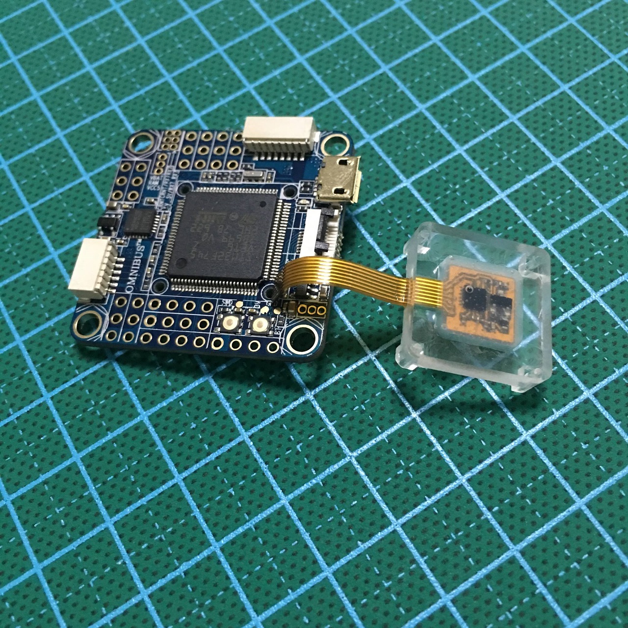
More details about original iFlight Revo Bee32 F7 V2 Flight Controller – it uses the STM32F745, ICM20608?over SPI also has on board secondary MPU6000 gyro. With onboard damping box, ICM20608?runs under 32k Gyro loop. Also onboard are a barometer and AB7456 OSD chip for the BetaFlight integrated OSD. iFlight Revo Bee32 F7 V2 supports 2-4s LIPO direct input, build in Current Sensor and Power Filter. Support 2-4S, comes with 5V 1A BEC output. Support SBUS, IBUS, DSMX, SUMD receivers.
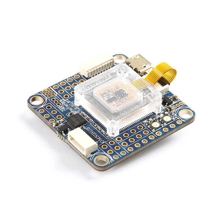
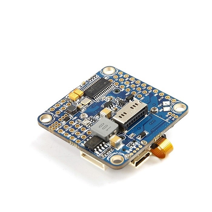

Also a cloned (?) board has appeared on the Banggood:?https://www.banggood.com/Omnibus-F7-V2-Flight-Controller-STM32-F745-MCU-2-4S-Built-in-Betaflight-OSD-Dual-Gyro-30_5x30_5mm-p-1215667.html
Description:
Item name: Omnibus F7 V2 flight controller
MCU: STM32 F745 (Spi connected to Gyro)
MPU6000 (the 6 axis SPI Gyrometer + Accelerometer)
IMC268 (the 6 axis SPI Gyrometer + Accelerometer)
D-shot Support
Dual Gyro
Baro
BF OSD
microSD
Blackbox
Size: 36x36mm
Mount holes: 30.5×30.5mm
Weight: 10g
Default firmware: betaflight_3.2.0_OMNIBUSF7V2
SBUS, IBUS, DSM2, DSMX Receiver configuration: UART2
Features:
F7 MCU – faster than the current F3 and F4 processors.
Two gyros on the flight controller: an MPU6000 for sampling up to 8khz and ICM20608 for sampling up to 32khz.
Built in betaflight OSD
36x36mm, mount holes 30.5×30.5mm.
SD card reader for recording black box data (SD card not included).
Supports 2-4S natively
5V/3A regulator
Port for easy connection to 30A 4-IN-1 ESC (SH1.0 8P)