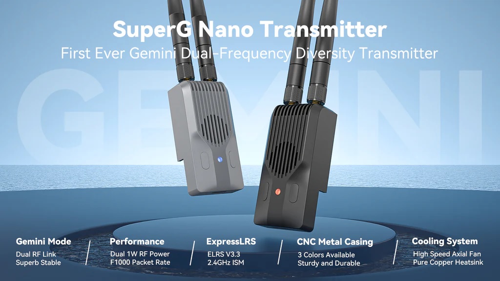
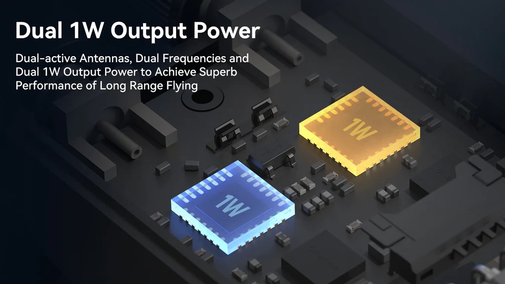
Dual 1W Output Power
BetaFPV SuperG Nano Transmitter has two RF chips, each boasting a powerful 1W transmission power. This power level with a combination of the LoRa radio transmission technology can get you 100Km range and beyond.
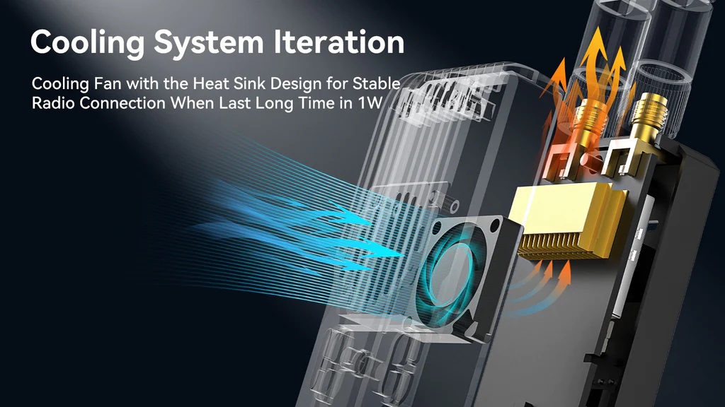
Active cooling system
Transmitter module casing is made of CNC aluminum alloy with efficient thermal conductivity, complemented by heatsink with active cooling fan for optimal heat dissipation.
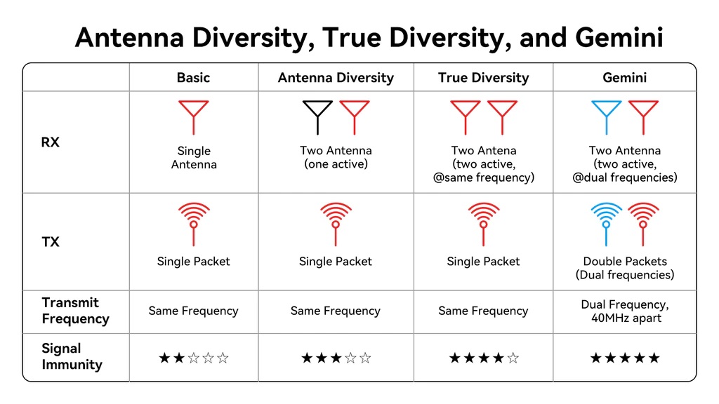
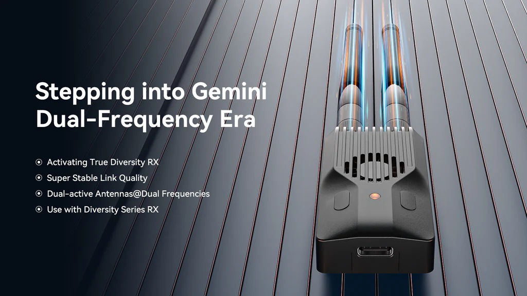
Antenna Diversity, True Diversity and Gemini mode
In the Antenna Diversity mode, two antennas are employed, and they are alternated regularly to assess the RSSI (Received Signal Strength Indicator) value of the signal. This assessment helps determine which antenna should be used for data reception.
In the True Diversity mode, receiver uses two radio chips, each connected to a different antenna. Both antennas receive data on the same frequency simultaneously and the antenna that has the strongest reception at any given time is used.
Meanwhile, in the advanced Gemini mode, two radio chips and two antennas simultaneously receive data with a 40MHz frequency difference. They also transmit telemetry data concurrently but on the different frequencies. This unique approach allows the reception of identical data packets on distinct frequencies and antennas. Gemini mode excels in maintaining stable flight, even in complex radio environments.
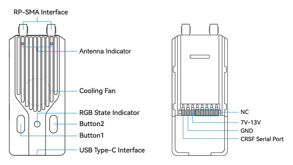
BetaFPV SuperG Dual Diversity Transmitter offers two customizable buttons and a USB Type-C port for . RGB LED for TX status display and 2 LEDs for each antenna status display.
Custom Buttons
BetaFPV SuperG Nano Transmitter reserves 2 buttons that can be customized by users. Here are the specific steps to operate:
- Enable the transmitter’s WiFi or power it on and wait for 60 seconds to enter WiFi mode using LUA programming.
- The RGB indicator light will slowly flash in green, indicating that the transmitter has automatically enabled WiFi (WiFi name: ExpressLRS TX, WiFi password: expresslrs).
- Connect your smartphone or computer to the WiFi network and open a web browser. Enter http://10.0.0.1 to access the custom button settings page.
- In the corresponding button’s Action column, select the desired custom function. Then, choose the button type and the number of presses or duration in the Press and Count columns. Click SAVE to complete the settings.
Currently, there are 6 available functions that can be assigned to shortcut buttons. There are 2 ways to use the buttons: long-press and short-press. The duration of a long press can be customized, while the number of presses for a short press can also be customized. The following are the 6 functions that can be set:?
| Unused | VTX Setting |
| Increase Output Power | Enable WiFi |
| Enter VTX Channel | Enter Binding Mode |
| Enter VTX Band |
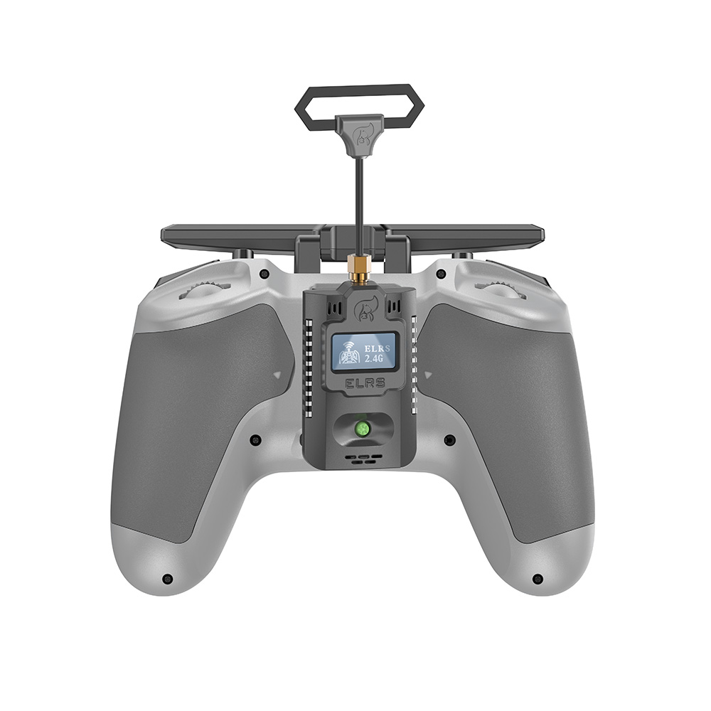
The pictures below show the functionality of the transmitter in its factory default settings. (The left button is Button1 and the right button is Button2).
| Button | Action | Press | Count |
| Button1 (Left Button) | Enter Binding Mode | Short Press | 3?Times |
| Increase?Power | Long?Press | For?0.5?seconds | |
| Button2 (Right Button) | Go to VTX Channel Menu | Short Press | 2?Times |
| Send?VTX?Settings | Long?Press | For?0.5?seconds |
BetaFPV ELRS TX modules comparison table
| SuperG Nano TX | Nano TX | Micro TX | |
| Max RF Power | Dual–1000mW | 500mW | 500mW/1000mW |
| RF Chip | Dual SX128x | Single SX128x | Single SX128x |
| Antenna Mode | Gemini | Single | Single |
| Cooling System | Yes | No | Yes |
| Backpack | Yes | No | Yes |
| External Power Supply | Yes, 7-13V | No | Yes, 5-12V |
Power consumption and external power
When the dual transmit power exceeds 500mW, the BetaFPV SuperG Nano Transmitter exhibits relatively high power consumption, leading to a reduced battery life. To prolong the transmitter’s usage time, it is advisable to utilize an external battery as a power source.
The power consumption of the transmitter is not only related to the transmit power but also to the telemetry ratio. When using high power of 500mW and above, the return ratio can be set higher to reduce power consumption and extend use time.
For example, in Gemini mode, the power consumption of setting the return ratio to 1:128 is 1000mA, while the power consumption of setting the return ratio to 1:2 is only half of 1:128.
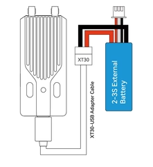
Note: When the voltage of the radio transmitter battery or external battery is lower than 7V (2S) or 10.5V (3S), please use the Gemini mode of 500mW and 1W carefully, otherwise the transmitter will enter the restart state due to insufficient power supply, resulting in disconnection out of control.
Specifications: For those who appreciate the technical details, here are some key specifications of the SuperG Nano Transmitter:
- Antenna Connector: 2* RP-SMA
- RF Power: 25mw/50mW/100mW/250mW/500mW/1000mW
- Packet Rate: 50Hz/100Hz/150Hz/250Hz/333Hz/500Hz/D250/D500/F500/F1000
- Frequency Band: 2.4GHz ISM
- Input Voltage: 7V~13V DC
- Rated Current: 8V, 1000mA @ 1000mW, 1:128, Gemini mode
- USB Port: Type-C
- Fan Voltage: 5V
- Default Firmware Version: ExpressLRS V3.3.0
- Color Options: Black, Red, Grey
- Weight: 44.8g
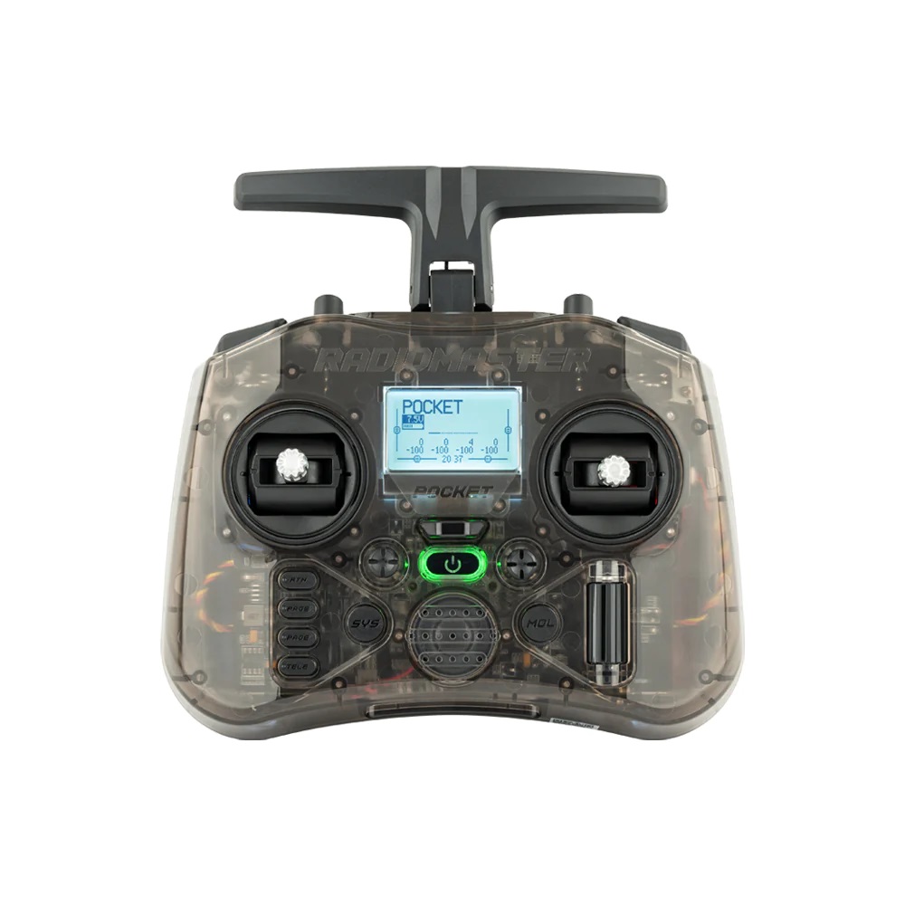
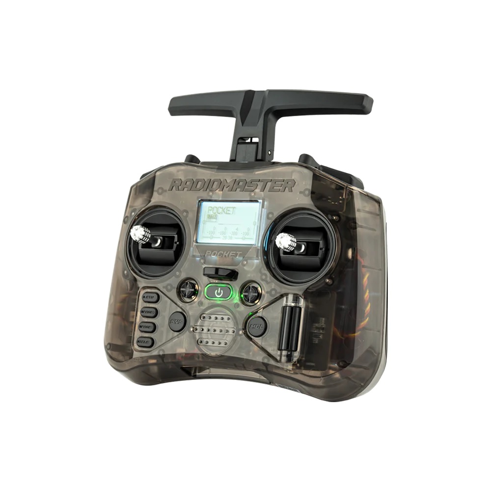

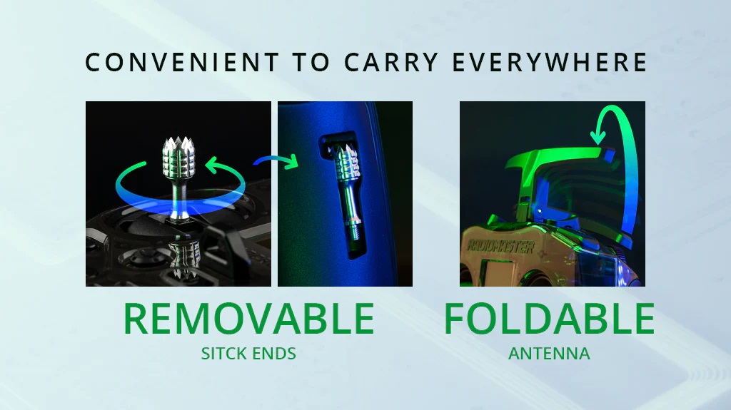
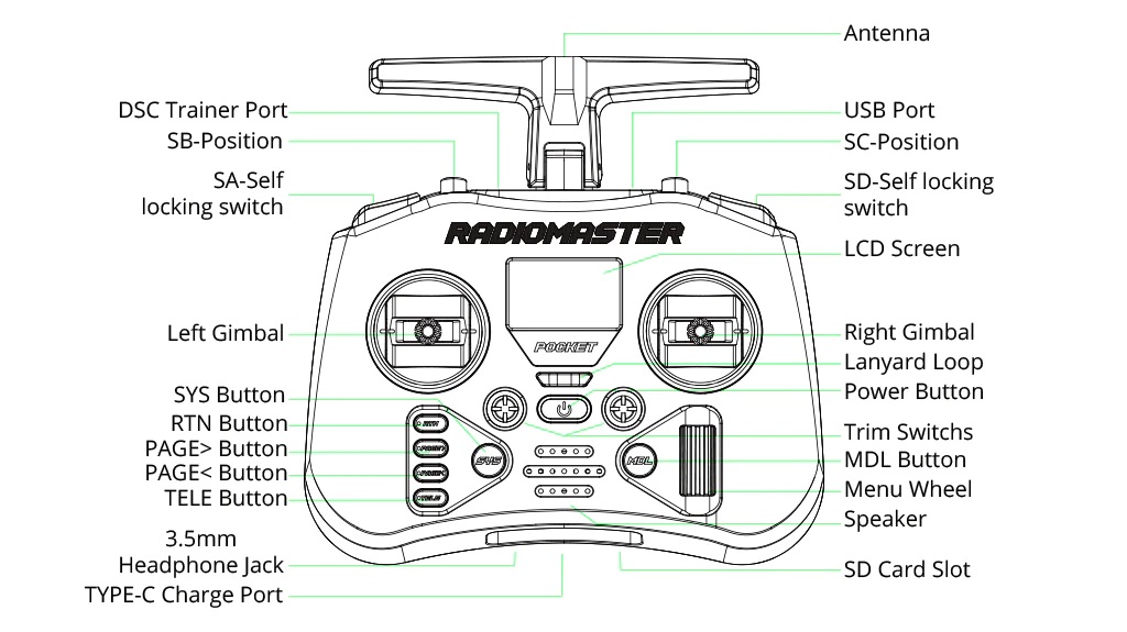
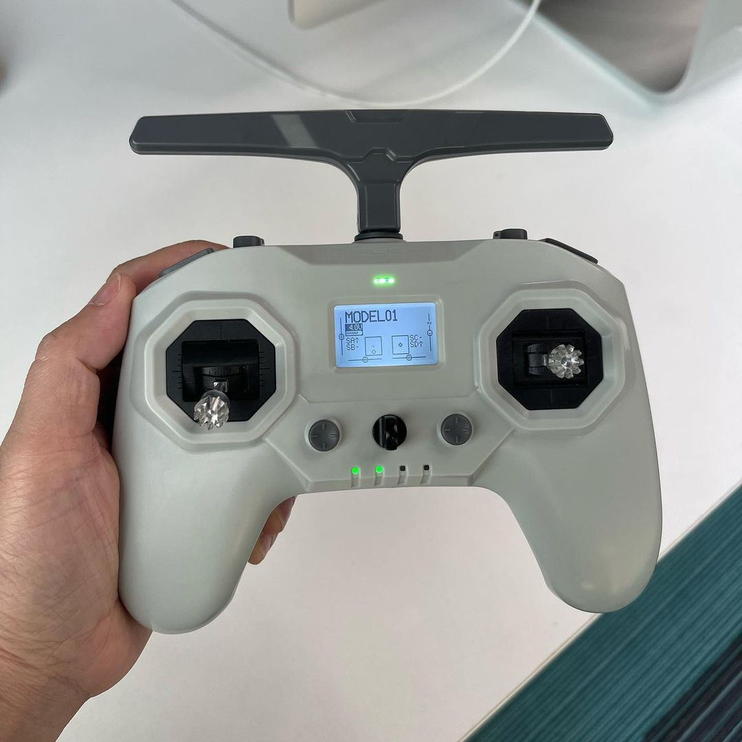
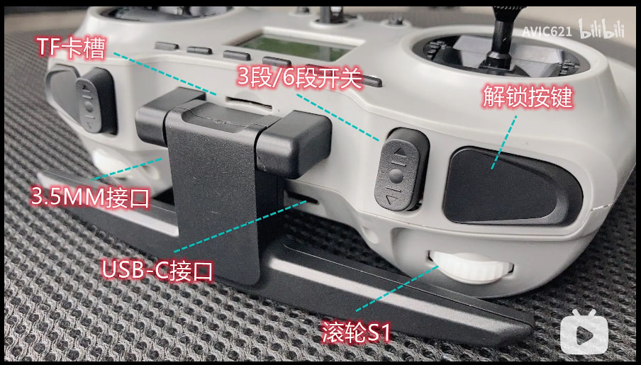
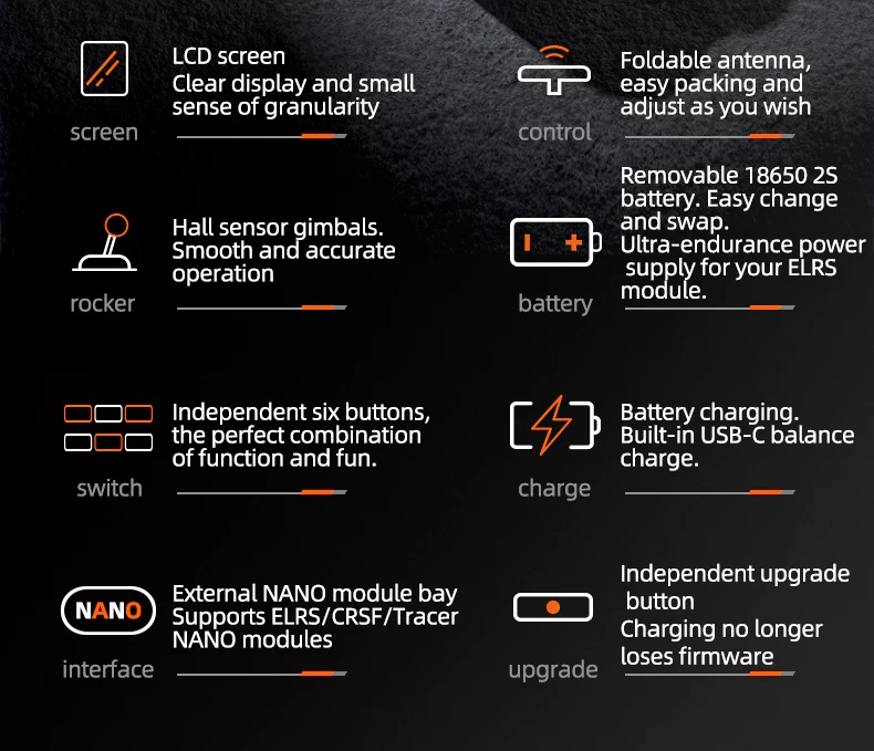
The Radiomaster Pocket Radio boasts a pocket-sized form factor, making it highly portable and easy to carry around. The 128×64 LCD display provides enough information, while the rubberized grips ensure a comfortable and secure hold. The inclusion of a lanyard strap hook allows users to keep the radio close at hand during the flying sessions.
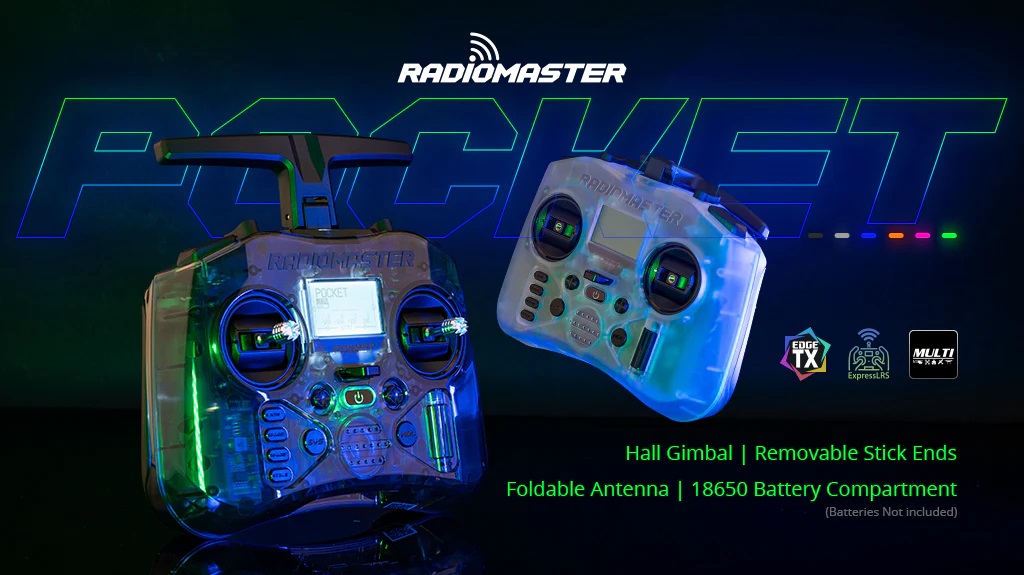
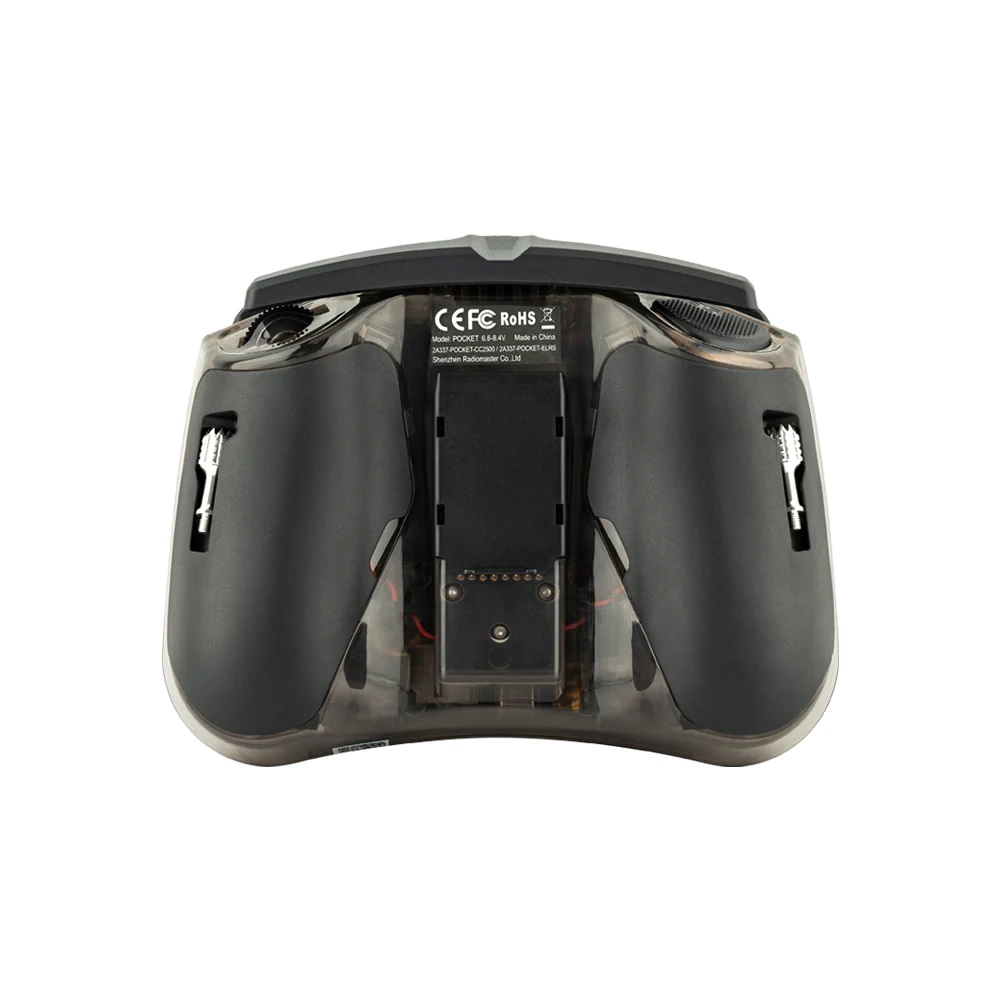
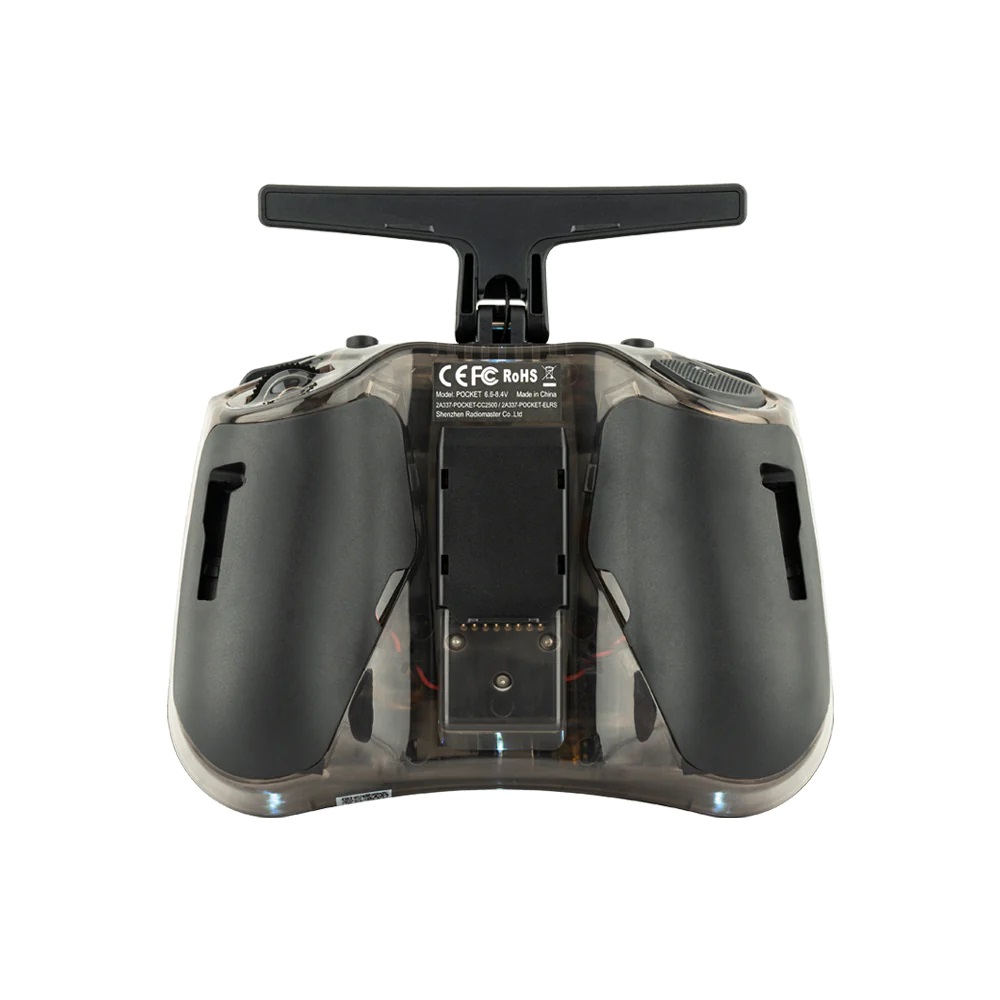
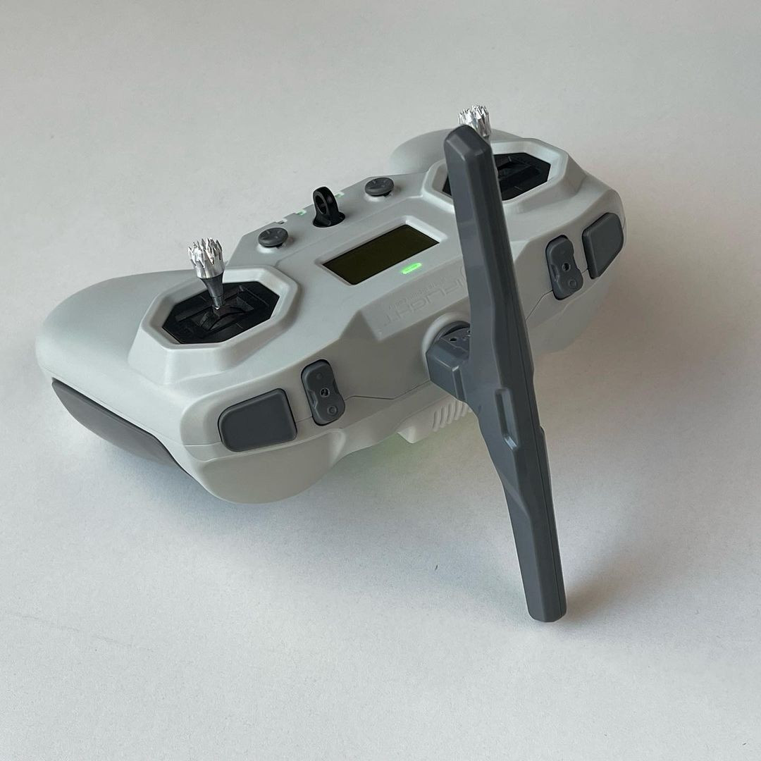
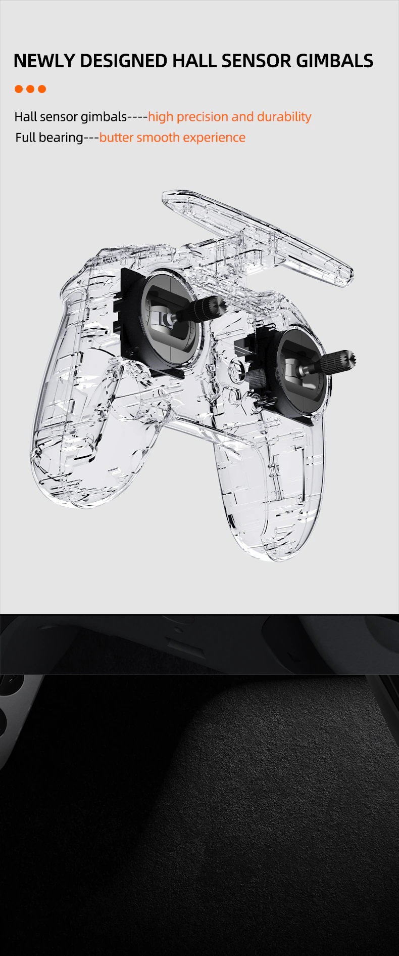
The two hall effect gimbals with removable stick ends provide precise control, and users can conveniently store the stick ends in special slots on the radio’s sides. Additionally, the removable antenna makes it easy to transport and store.
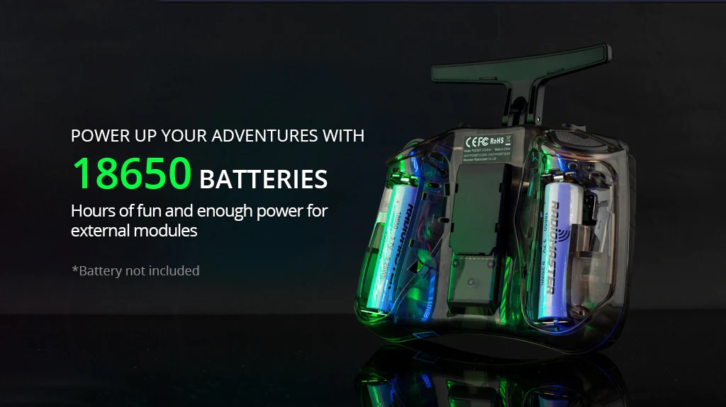
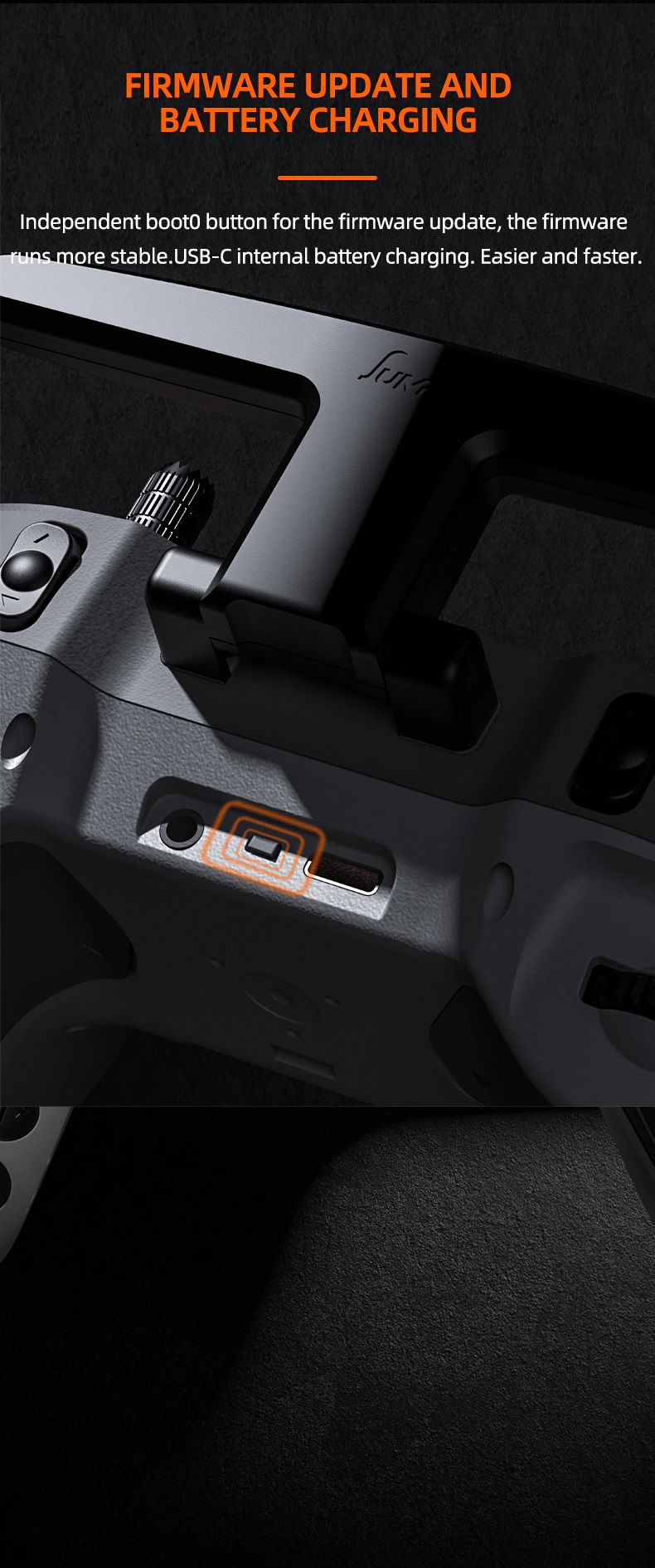
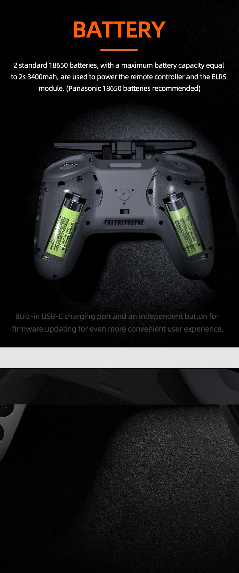
Powered by two 18650 lion batteries, the Radiomaster Pocket Radio offers hours of uninterrupted flying sessions. The USB-C charging port simplifies the recharging process.
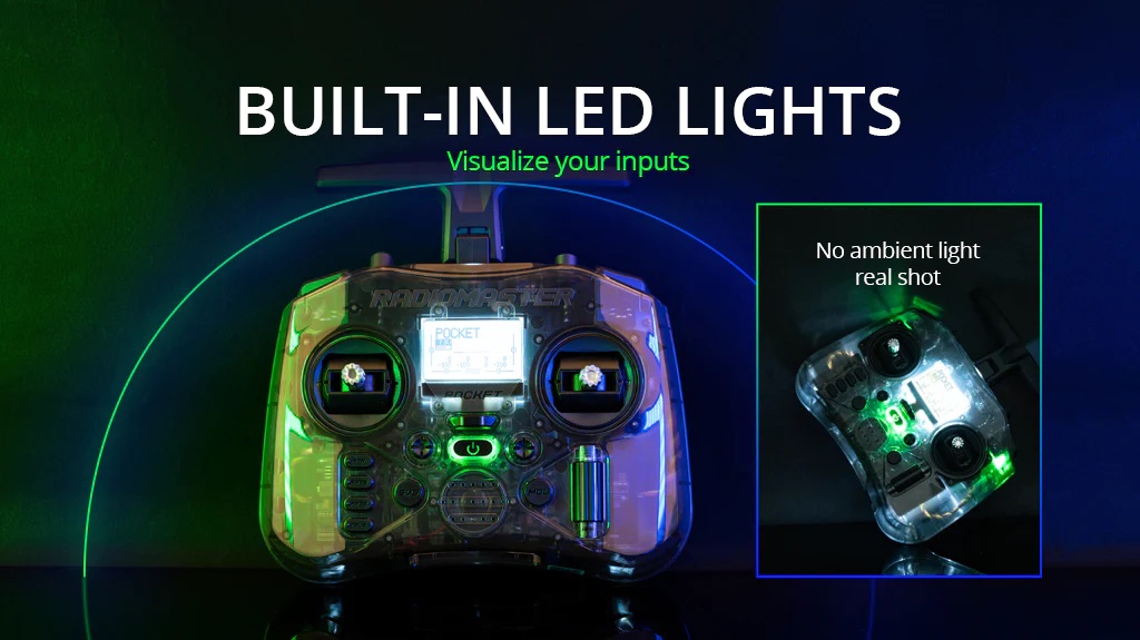
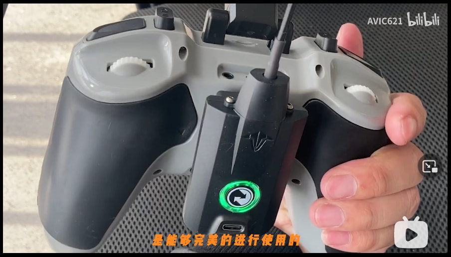
The built-in LEDs offer a simple yet effective way to visualize switch positions.
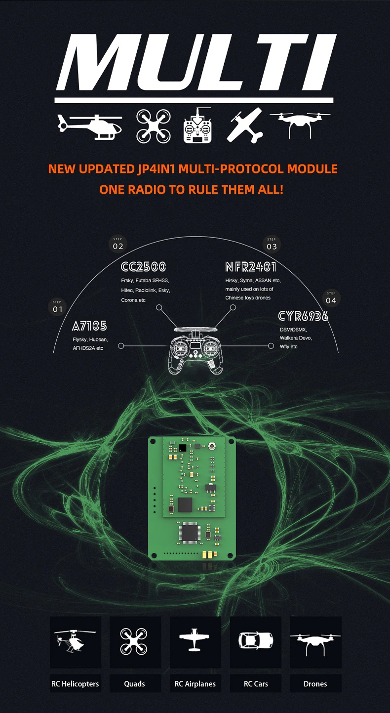
The RadioMaster Pocket Radio is available in two versions: the CC2500 Version and the ELRS (ExpressLRS) Version. The CC2500 supports a wide range of protocols, including popular ones like FrSky and Futaba. On the other option, the ELRS Version comes with internal ExpressLRS 2.4GHz TX module, delivering 250mW of maximum power. Both versions are equipped with the EdgeTX firmware.
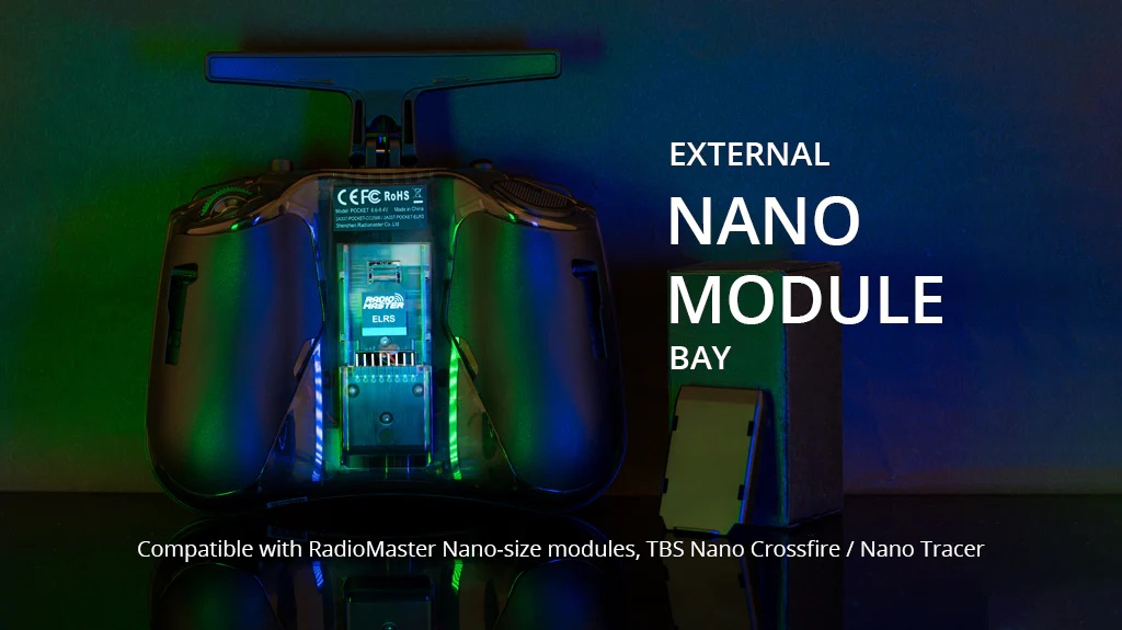
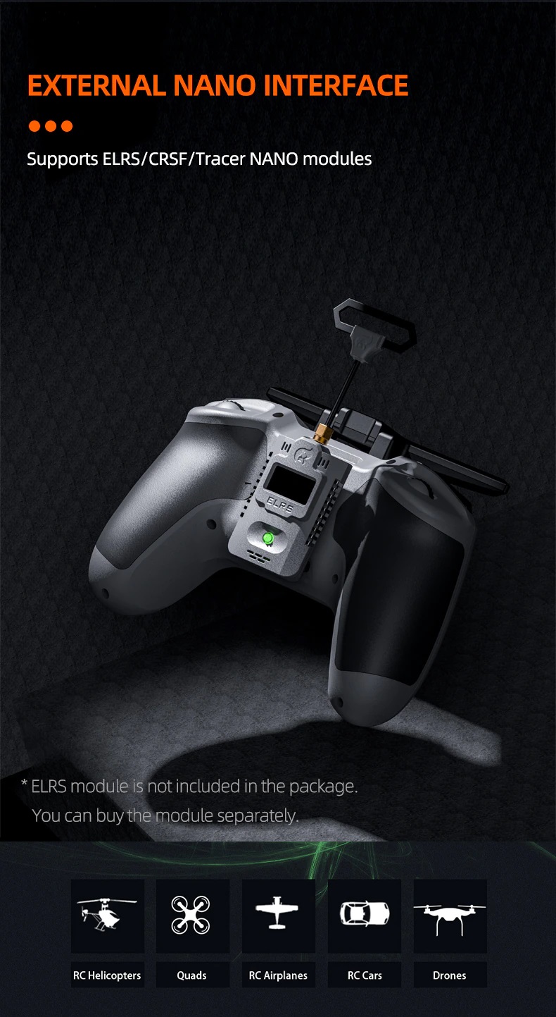
With the inclusion of a nano-sized external module bay, the Radiomaster Pocket Radio enables the use of various external modules.
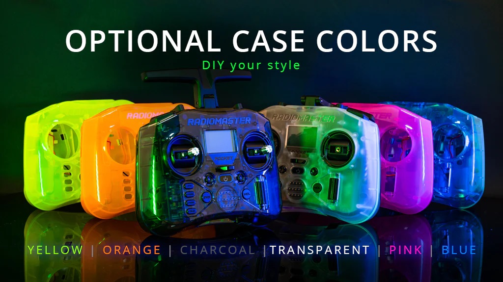
The RadioMaster Pocket is available in two color options, Charcoal and Transparent White. Furthermore, users have the option to choose from a selection of other colors to match their personal style and preferences.
Radiomaster Pocket Radio User Manual: No user manual yet.
Available @
Radiomaster: https://www.radiomasterrc.com/products/pocket-radio-controller-m2
Banggood: https://www.banggood.com/RadioMaster-Pocket-…-Radio-Controller
Specifications
Item: Pocket Radio
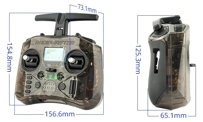
Physical dimensions: 156.665.1125.3mm (Folded size) /156.673.1154.8mm (Unfold size)
Weight: 288 grams
Operating frequency: 2.400GHz-2.480GHz
Internal RF Options: CC2500 multi-protocol / ELRS 2.4GHz
Supported protocols: Module dependent
RF power: CC2500:100mW Max (20dBm) / ELRS FCC: 250mW Max (24dBm) / ELRS EU-LBT: 100mW Max (20dBm)
Operational voltage: 6.6-8.4v DC
Control distance: > 2km @ 20dBm
Operating system: EdgeTX
Control channels: Maximum 16 (Receiver dependent)
Display: 128*64 Monochrome LCD
Battery: 2pcs 18650 batteries (Not included)
Charging: Built in USB-C QC3 Charging
Upgradable Firmware: Via USB or the included SD card
Gimbal: Hall-effect
Module bay: Nano size (Compatible with RadioMaster Nano-size modules, TBS Nano Crossfire / Nano Tracer )
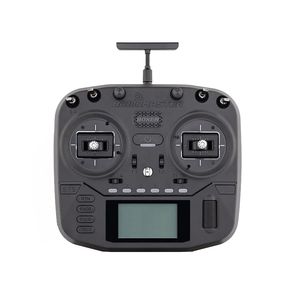
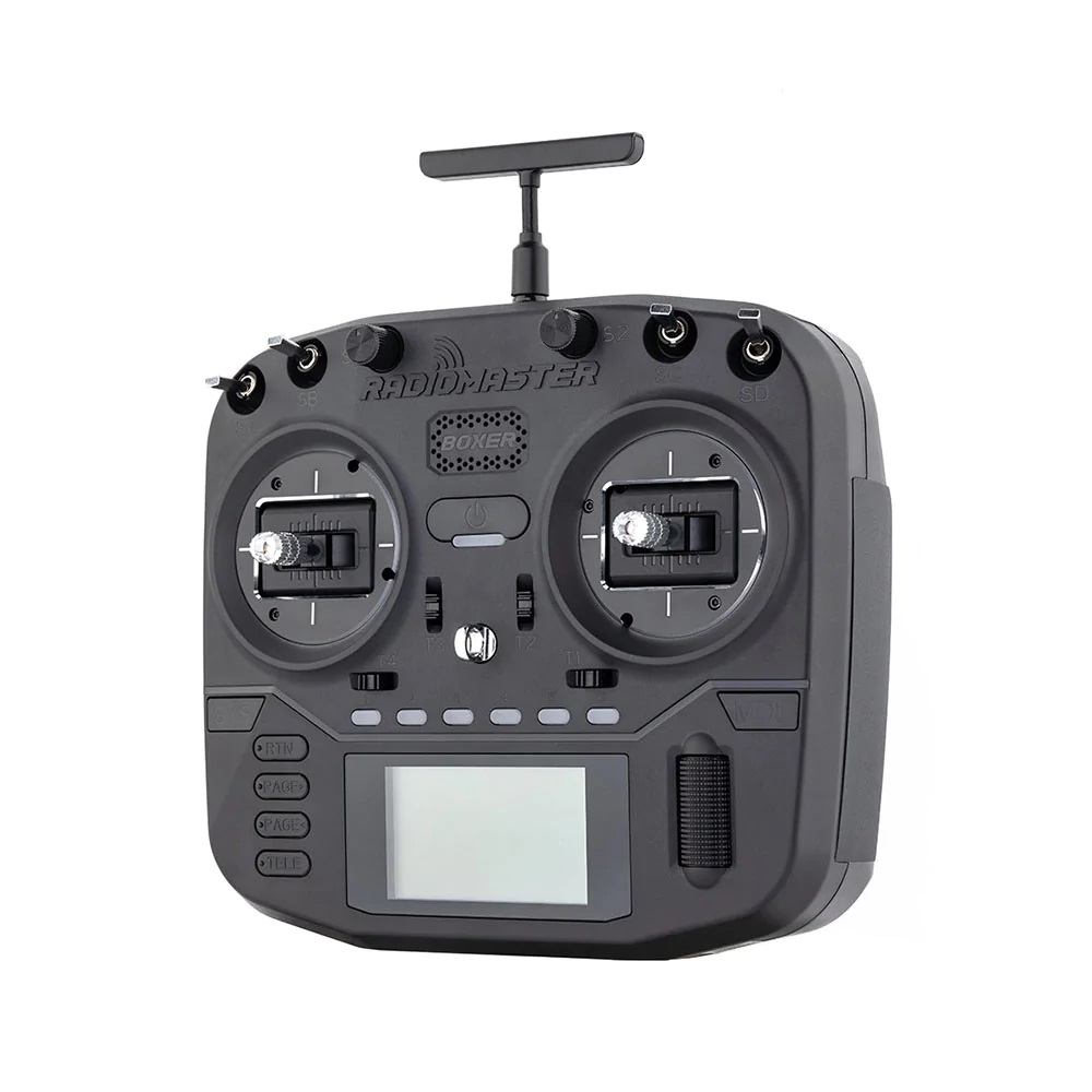
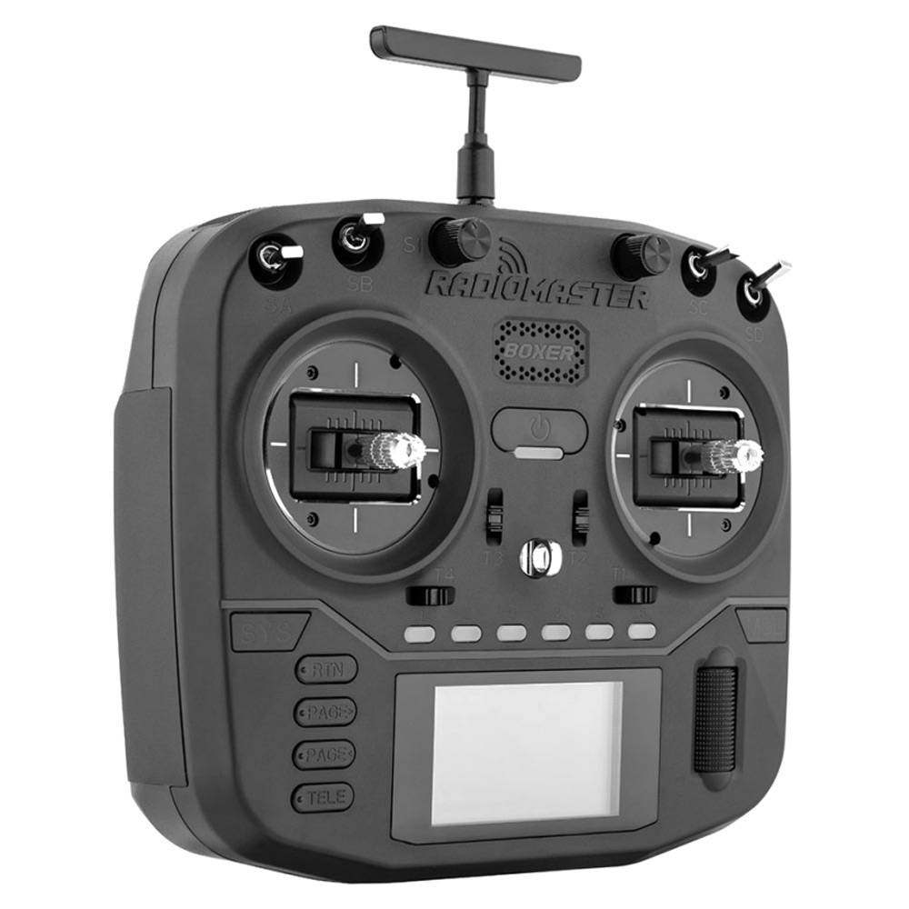
Radiomaster Boxer is wider (235mm) than Radiomaster TX16s radio (183mm), but is significantly shorter than TX16s, thus making it smaller and lighter radio. Design wise it has many similarities with TBS Mambo radio, probably could be called inspired by it.
On the top side of the radio you will find the new latching push switch and momentary switch. Just like on the TBS Mamba radio.
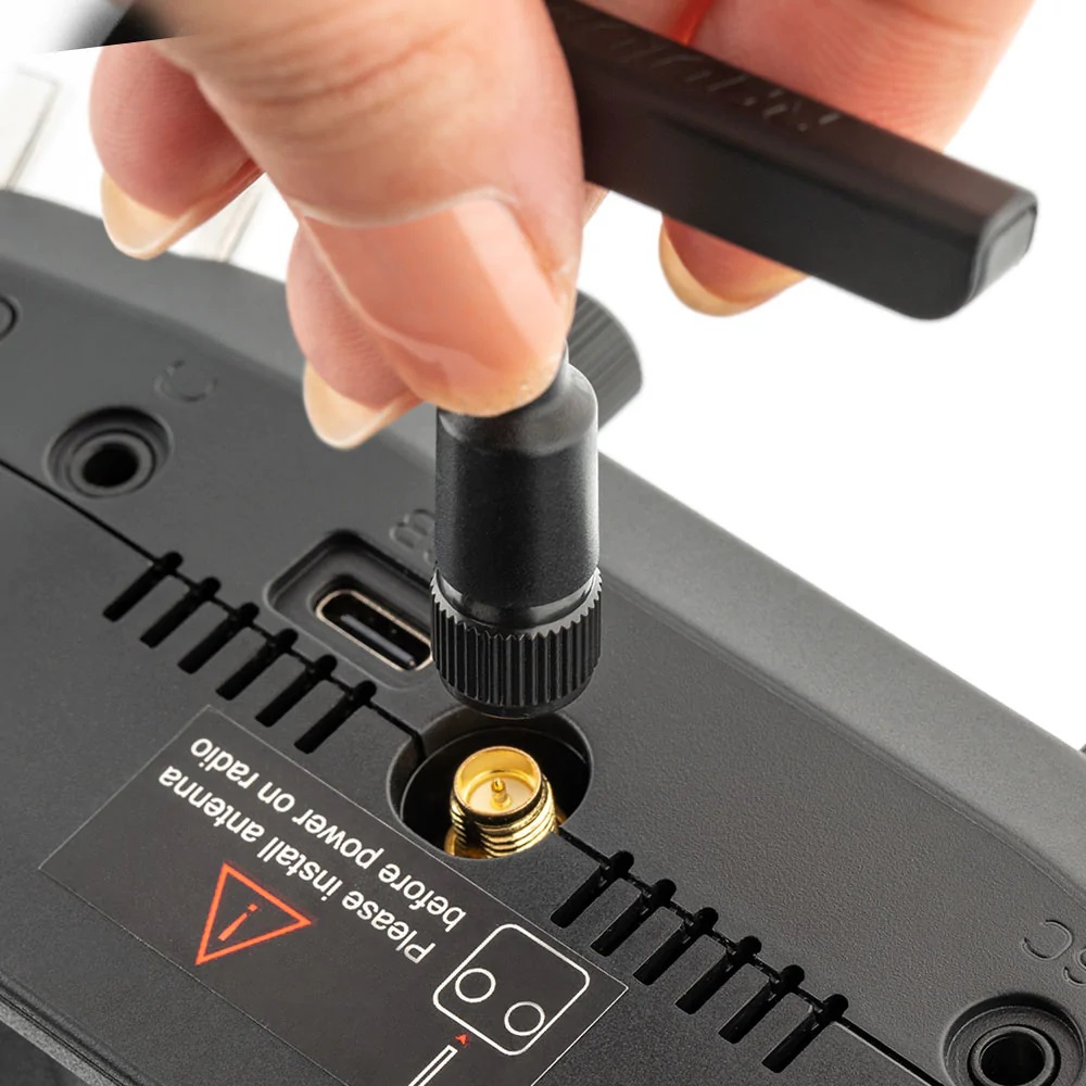
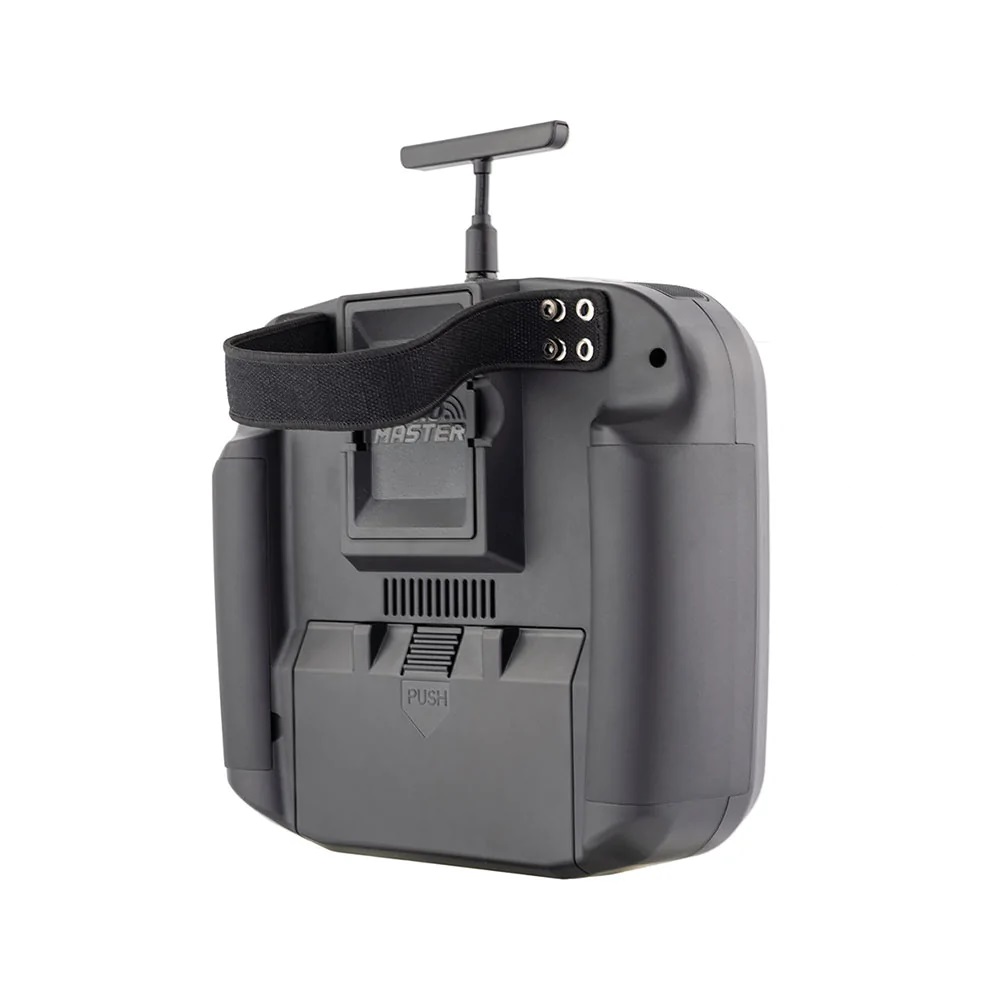
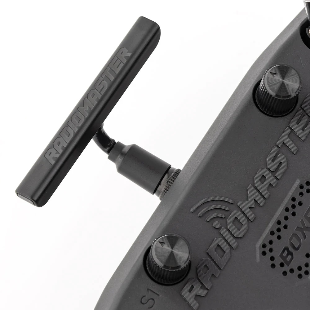
Boxer has T-shape bendable and removable antenna.
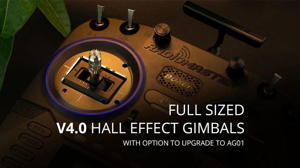
Radiomaster Boxer has full size easy adjustable gimbals. They can be upgraded with the high quality AG01 gimbals
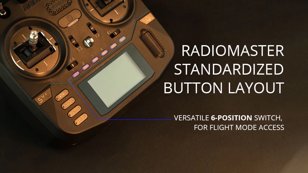
6 position switches were moved from the top to the bottom part, right over the LCD screen. By the way it was Jumper who introduced them first.
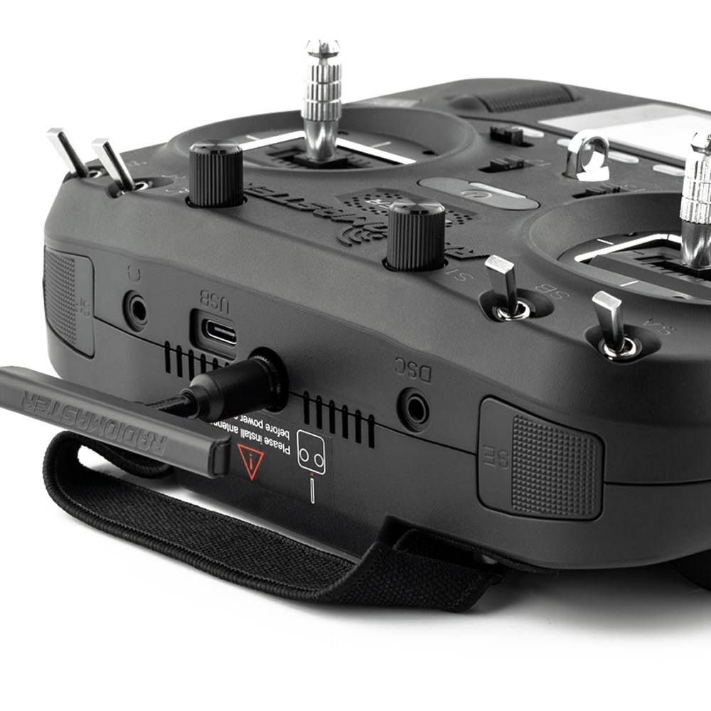
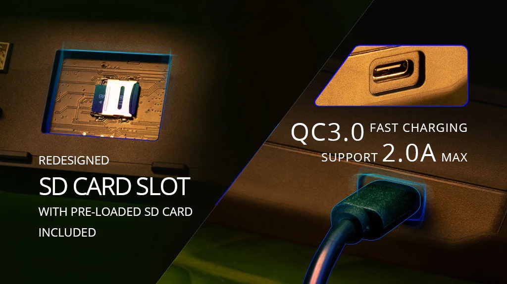
Boxer can be charged by USB-C cable with a charger supporting QC3.0 fast charging with up to 2.0A.
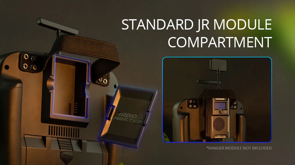
Radiomaster Boxer also has standard JR type bay for full size external modules.
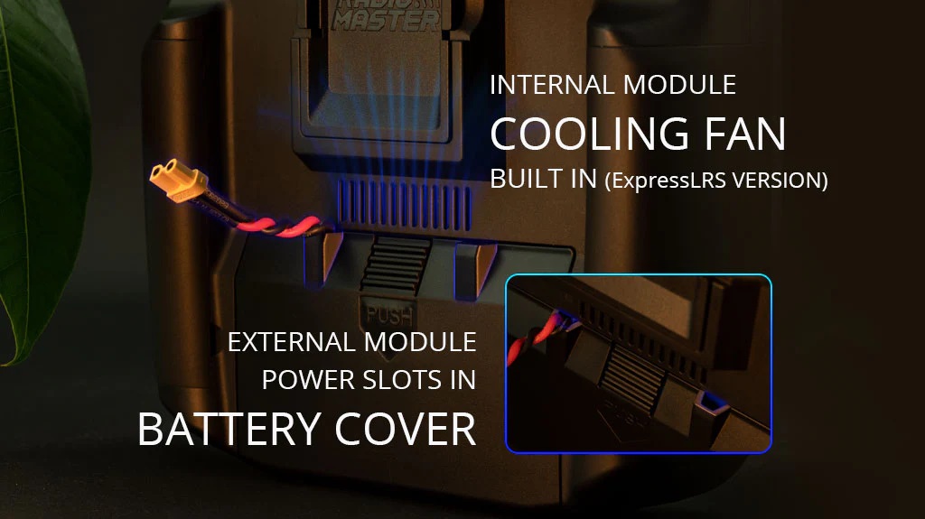
Internal ExpressLRS module provides up to 1W of RF output and is actively cooled with internal cooling fan.
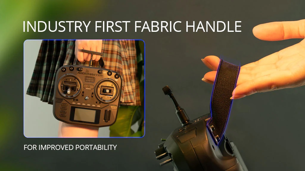
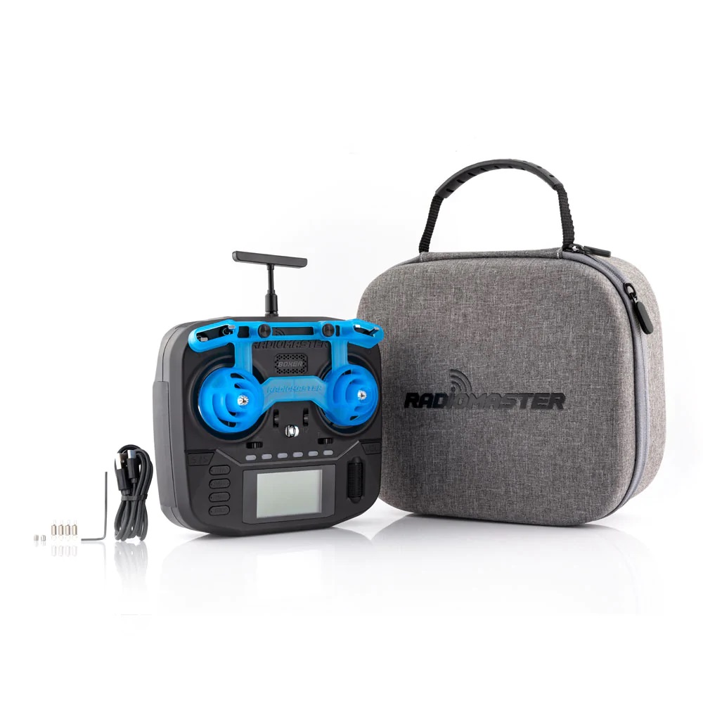
Radiomaster Boxer has never seen before soft fabric handle for weight and space savings.

Radiomaster Boxer can be purchased @
RadioMaster: https://www.radiomasterrc.com/products/boxer-radio-controller-m2
Features
- Available with built-in ExpressLRS or 4-in-1/CC2500 MPM RF modules
- Featuring a powerful STM32VGT6 processor with 1MB RAM
- Preinstalled EdgeTX firmware
- Internal ELRS module capable of 1,000Hz refresh rate
- Adjustable ELRS RF output (30dBm max FCC or 20dBm Max EU LBT)
- 4-in-1 or CC2500 only version capable of up to 20dBm RF output
- QC3.0 fast charging support 2.0A MAX
- Compact design with excellent ergonomics
- New low-profile latching SE switch and momentary SF switch
- Oversized battery compartment- Space for a 2S 6200mAh pack, up to 20-hour duration (Batteries not included)
- Full sized V4.0 Hall effect gimbals as standard, upgradable to AG01 CNC Hall effect gimbals
- Standard JR module compartment
- Internal module cooling fan built in (ELRS version)
- RadioMaster standardized button layout
- Versatile 6-position switch for flight mode access
- Adjustable and Removable T-shape Antenna
- Industry first fabric handle for improved portability
- Changeable, ergonomic grips
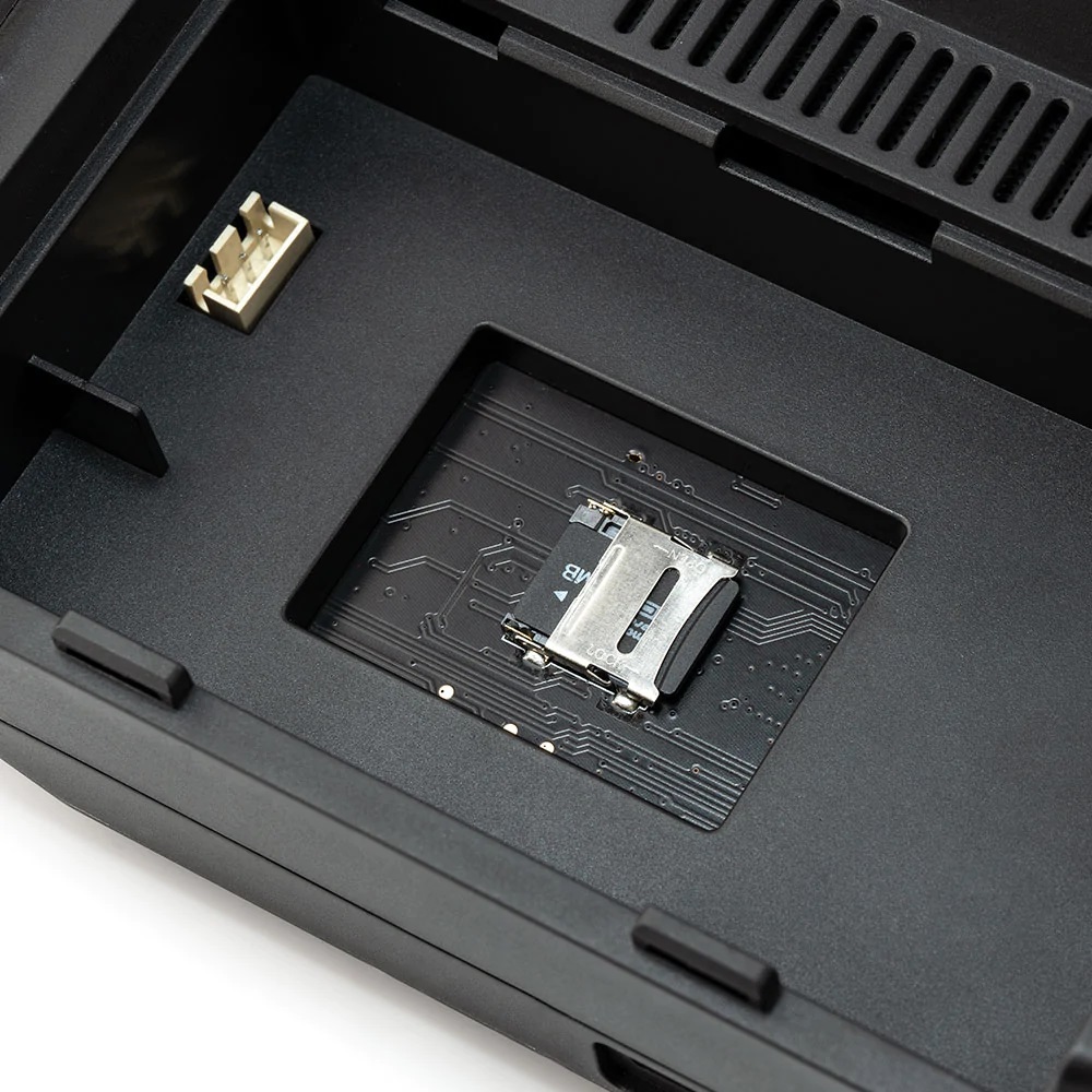
- Redesigned SD card slot with pre-loaded SD card included
- External module power slots in battery cover
- RadioMaster signature carry case and gimbal protector are included as standard to ensure your radio stays safe while on the move
Specification
- Item: BOXER Radio
- Size: 235*178*77mm
- Weight: 532.5g
- Frequency: 2.400GHz-2.480GHz
- Internal RF Options: CC2500 multi-protocol / 4-in-1 multi-protocol / ELRS 2.4GHz
- Supported protocols: Module dependent
- Transmitting Power CC2500 and 4IN1: Max 20dBm
- Transmitting Power ExpressLRS: Max 30dBm (international) / Max 20dBm (EU LBT)
- Cooling fan: Built in (ELRS version)
- Voltage Range: 6.6-8.4V DC
- Radio Firmware: EdgeTX (Transmitter) / Multi-Module (RF module) / ELRS
- Channels: Max 16 channels (Receiver dependent)
- Battery: 7.4V 2-cell Lithium-Polymer / Two 3.7V 18650 Lithium-Ion cells (batteries not included)
- Display: 128*64 Monochrome LCD display
- Gimbal: High precision 4.0 Hall gimbals as standard (AG01 Optional)
- External module: JR/FrSKY/Crossfire compatible
- Upgrade Method: USB/SD card & EdgeTX Companion PC software
Radiomaster Boxer Radio User Manual: https://cdn.shopify.com/s/…/files/Boxer_Radio_User_Manual.pdf
]]>
?
DIY ExpressLRS TX Nano module
Remarks
DIY Nano TX module build uses modular design it means it uses pre build modules. Only a few additional components are used (one resistor and one capacitor). Almost anyone could build this TX module with little soldering experience.?
Nano sized DIY TX module can be installed in the full and nano size JR module case. It can be even installed inside the radio as it is really small.
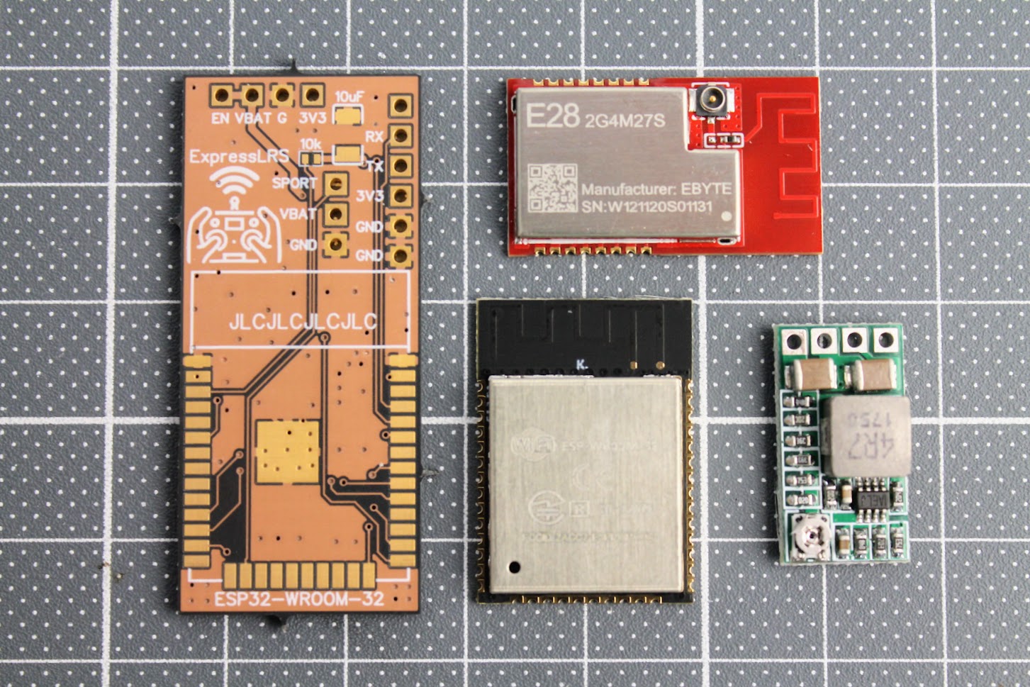
TX Parts list
Parts list starts from PCB. I have ordered the PCB on OSH Park?(https://oshpark.com/shared_projects/K4feONmv).?The cost of PCB was $7.10?for?3pcs.
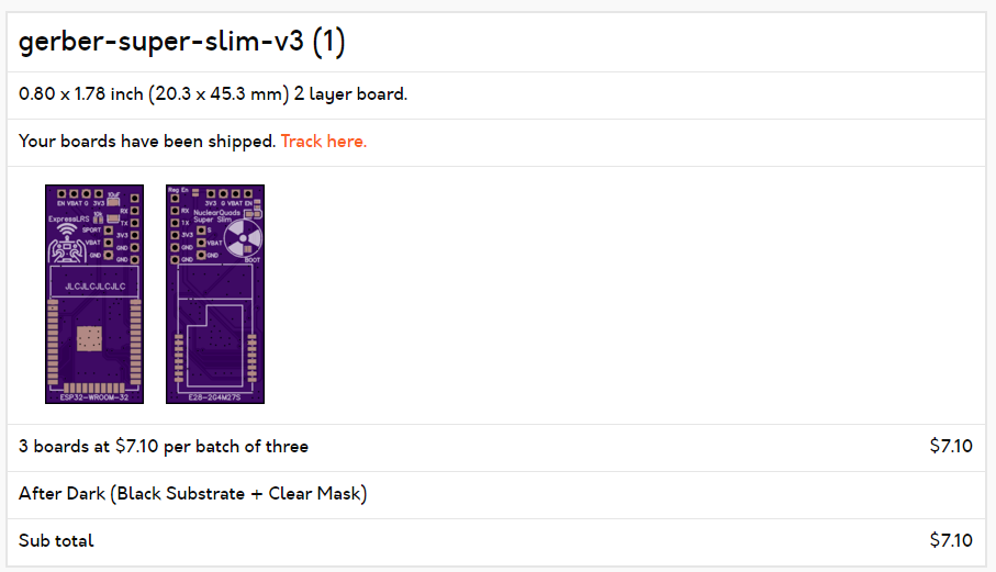
The original gerber files for PCB manufacturing can be found here:?
https://github.com/ExpressLRS/ExpressLRS-Hardware/tree/master/PCB/2400MHz/TX_SX1280_Super_Slim
I have purchased all the electronic parts from Aliexpress as it was the cheapest source.
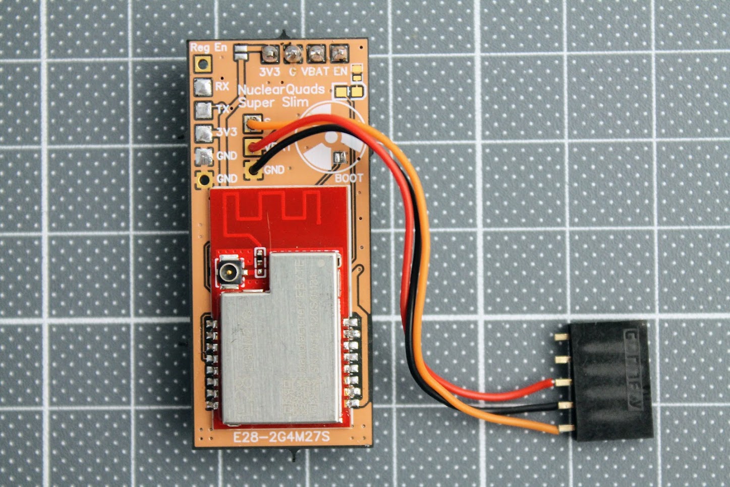
E28-2GM27S LoRa module (~$14) –?https://www.aliexpress.com/item/1005001812234542.html
ESP-WROOM-32? module (~$5) –?https://www.aliexpress.com/item/1005001833545594.html
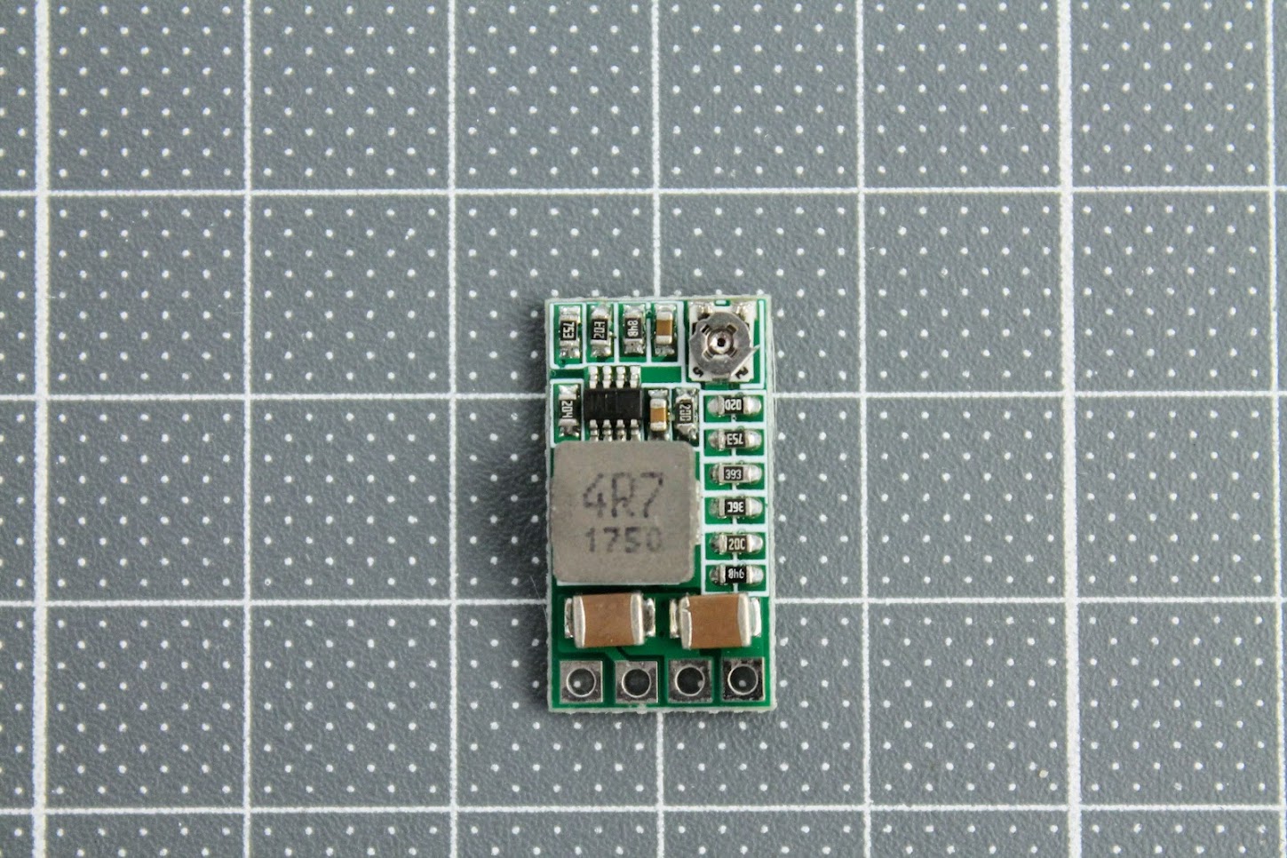
DC-DC power supply?module (~$2.5) – https://www.aliexpress.com/item/32880983608.html
SMA antenna pigtail (~ $0.5/pcs) –?https://www.aliexpress.com/item/4000848776660.html
Also you will need 10uF SMD capacitor (3528 or type B size) and the 10k?SMD resistor (0402 size).
Other things you will need: 5 pin 2.54mm header socket, silicone wires and of course a soldering iron set.
Build process
Soldered the ESP32-WROOM module and 10k resistor and 10uF capacitor. Soldering the resistor is the trickiest part as resistor is tiny (0402 size).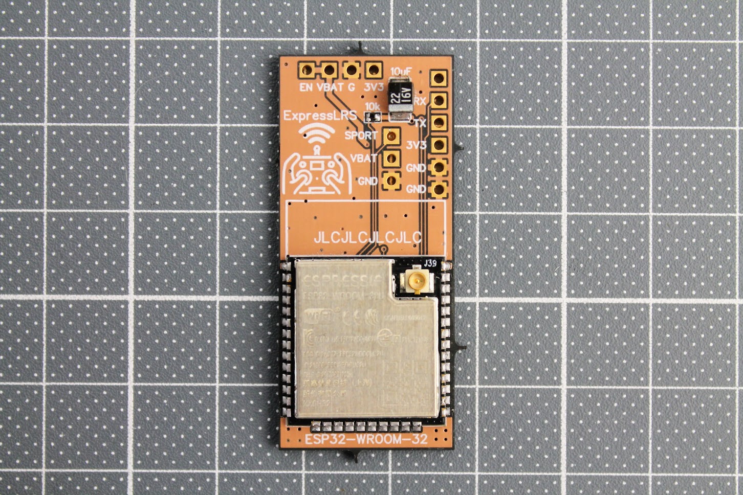
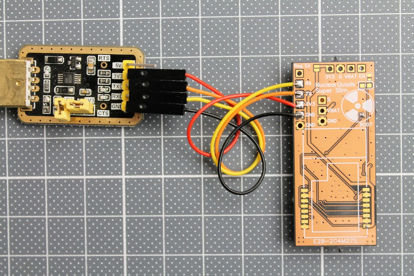
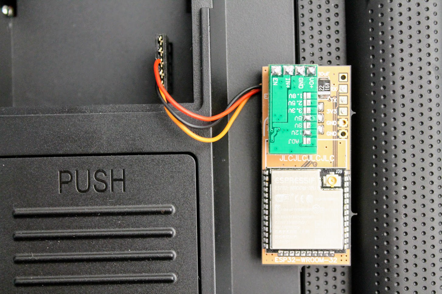
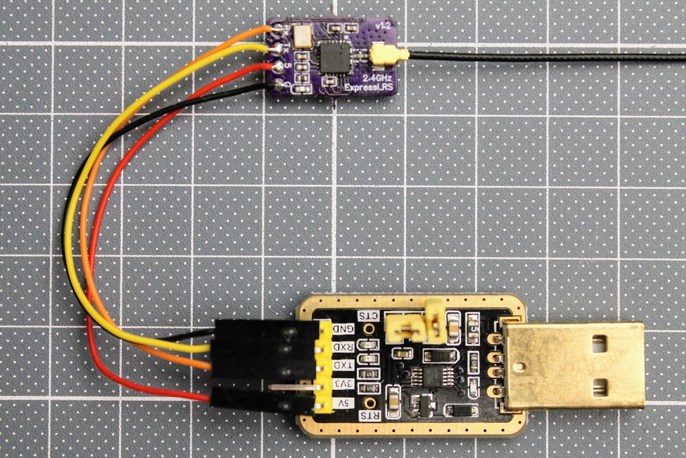
After the ESP32 module is soldered, you need to tempararily solder the RX, TX, 3.3V and GND wires. Connect these wires to the corresponding pins on the FTDI or any other USB to serial adapter. You can even use Arduino board. Don’t forget to short the BOOT pads for flashing the firmware by UART.
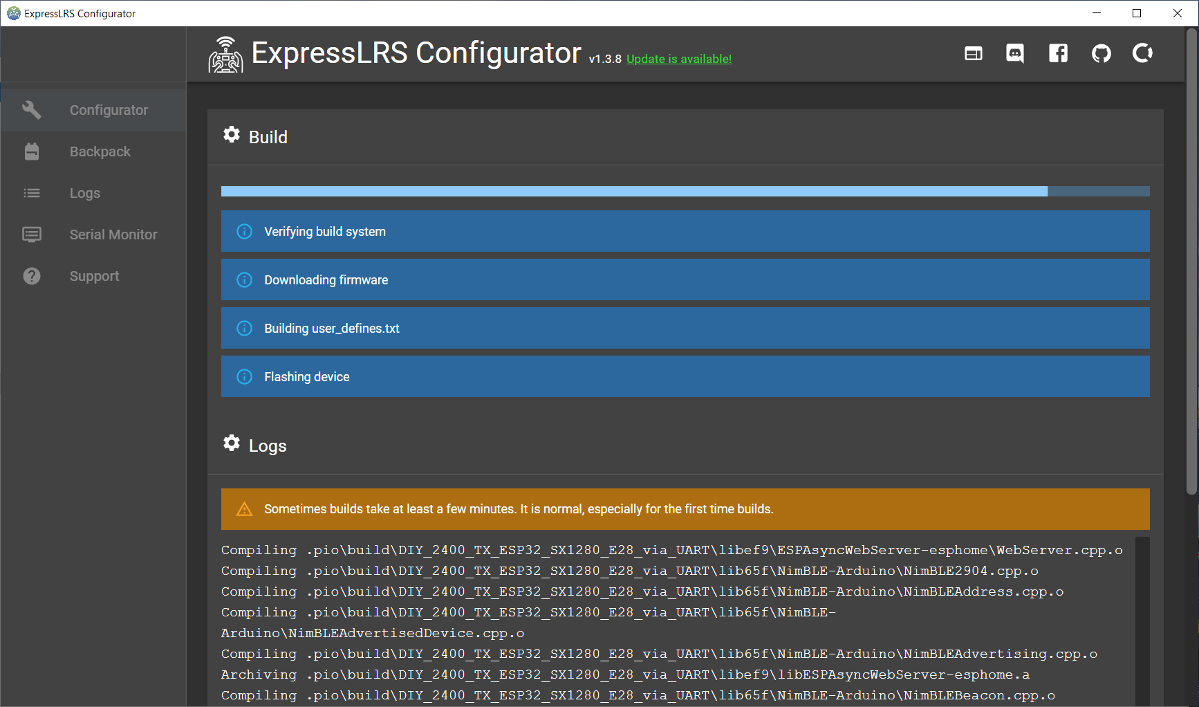
At this stage I would recommend to flash the ExpressLRS firmware to the ESP32-WROOM-32 module. For
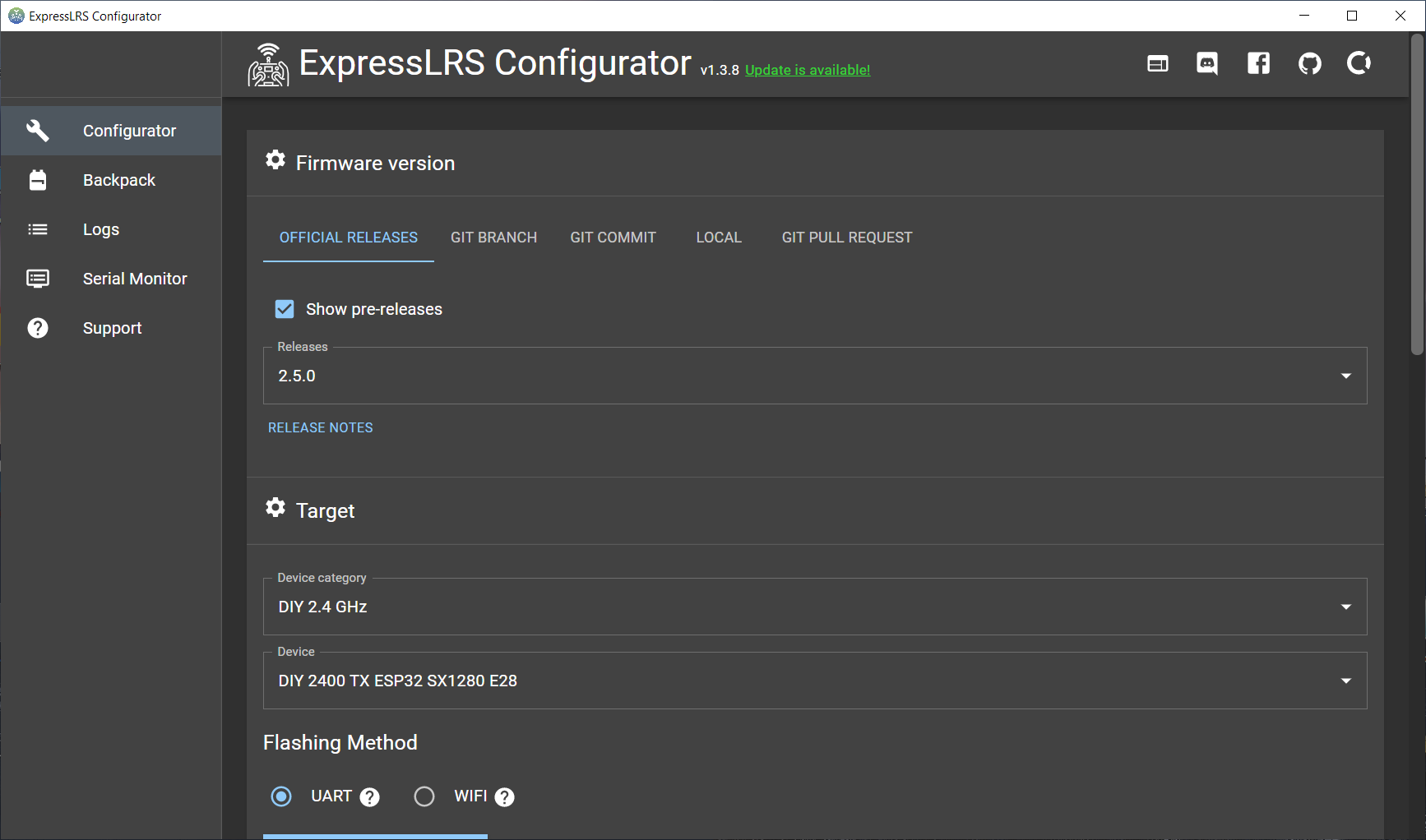
Start the ExpressLRS Configurator. You can download it from here:?https://github.com/ExpressLRS/ExpressLRS-Configurator/releases/?
Select “DIY 2.4 GHz” as Device category and “DIY 2400 TX ESP32 SX12800 E28” as Device.
Select UART as Flashing Method.
Read more about the flashing the ExpressLRS here:
ExpressLRS Open Source Long Range radio control system – Complete Guide
Press [Build & Flash]. Wait several minutes for it to compile.
And flashing successful!
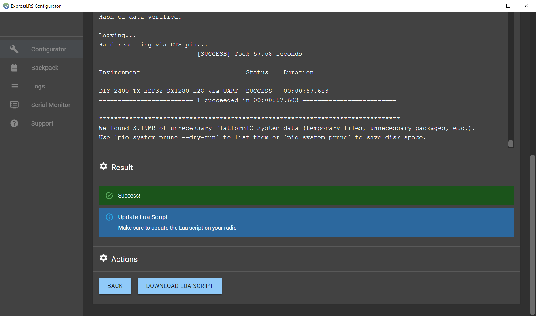
Now you can unsolder the FTDI (USB to Serial) adapter.
Next step solder the JR bay connector.
Prepare the power (voltage regulator) module. Short the 5V and 12V pads on the back side of the DC-DC regulator module. This will set the regulator to output the 3.45V, which is slightly more than 3.3V, but within the 5% tolerance of the modules.?
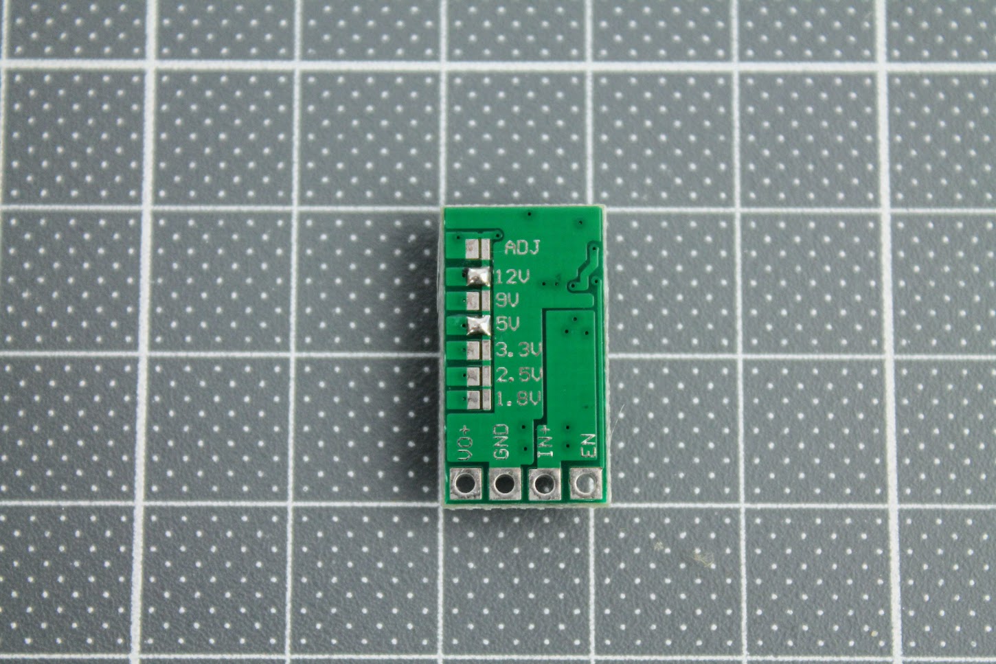
Turn the variable resistor to the clockwise end position (more about it below).
And solder the module to the EN, VBAT, G and 3V3 with the help of the pin headers.
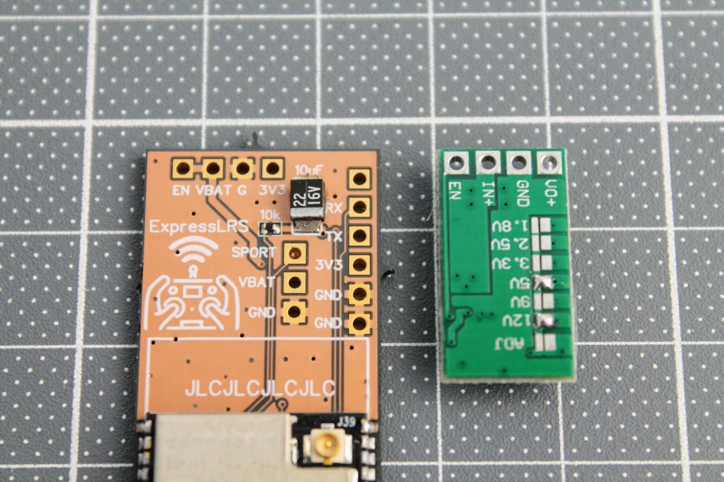
I also would like to suggest to connect the ExpressLRS module to the JR bay, power the radio, enable the External module in the model setup and measure the voltage between the GND and VO+ pads. It should be slightly more than 3.3V, the recommended voltage is 3.45V. In my case I have measured the voltage 3.58V, which is in the range of the absolute maximum voltage ratings (+10%) for the ESP32 and E28 modules, but its not recommended to operate the modules at this voltage, so I have turned slightly the dial on the variable resistor to set the 3.45V, which is 5% more than standard power voltage for modules. In theory E28 module should be happy to have a slight voltage overhead.
I need to notice, that at this point the ESP32 and E28 modules are not powered as the Reg En jumper pads are not connected.
Once the power voltage is set and verified, you can short the?Reg En solder pads and solder the E28-2GM27S module.
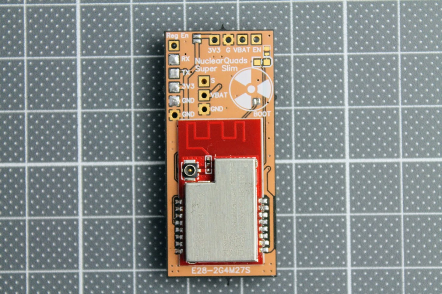
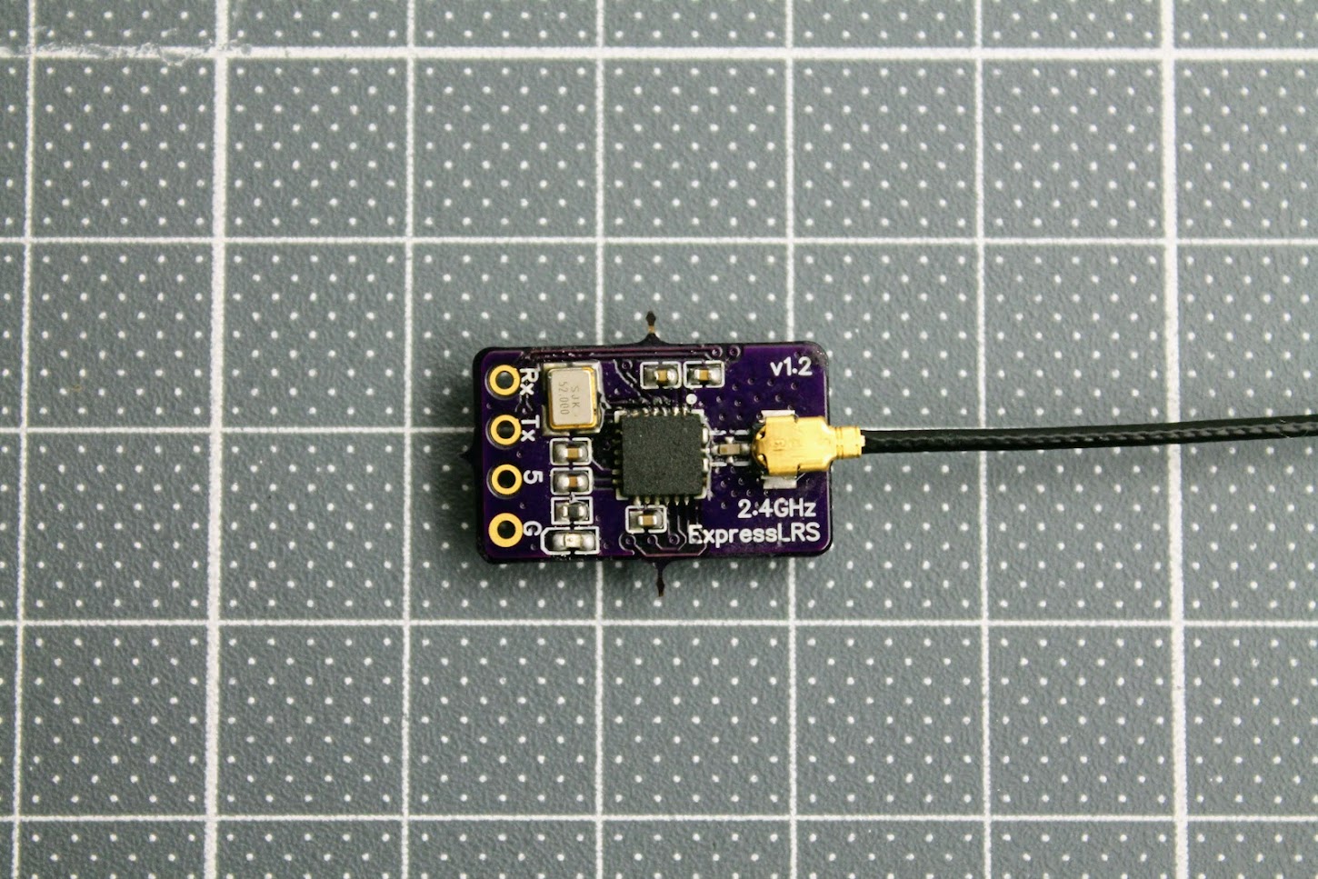
Another tricky part is to switch the zero Ohm resistor from the PCB antenna to the external (ipex) antenna position. I ended up just making the solder blob between the two pads as the resistor is zero ohms anyway.
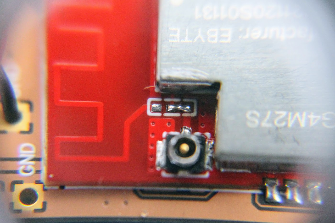
Completely assembled with all the antennas connected. Notice that 3.3V?power line Reg En jumper pads are soldered near the top right corner of the PCB board.
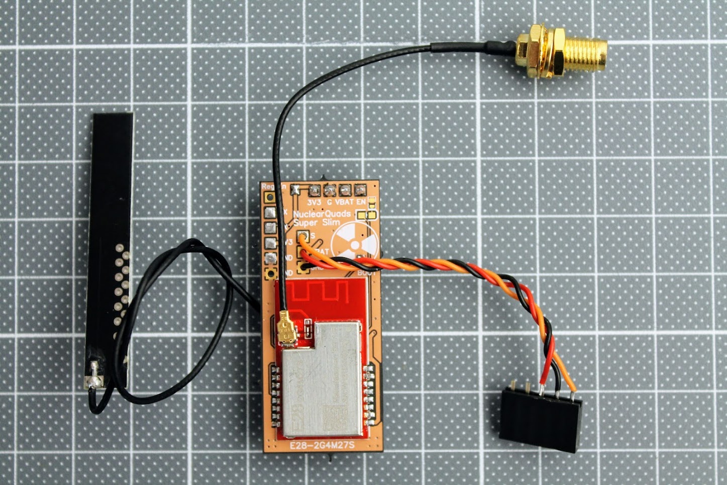
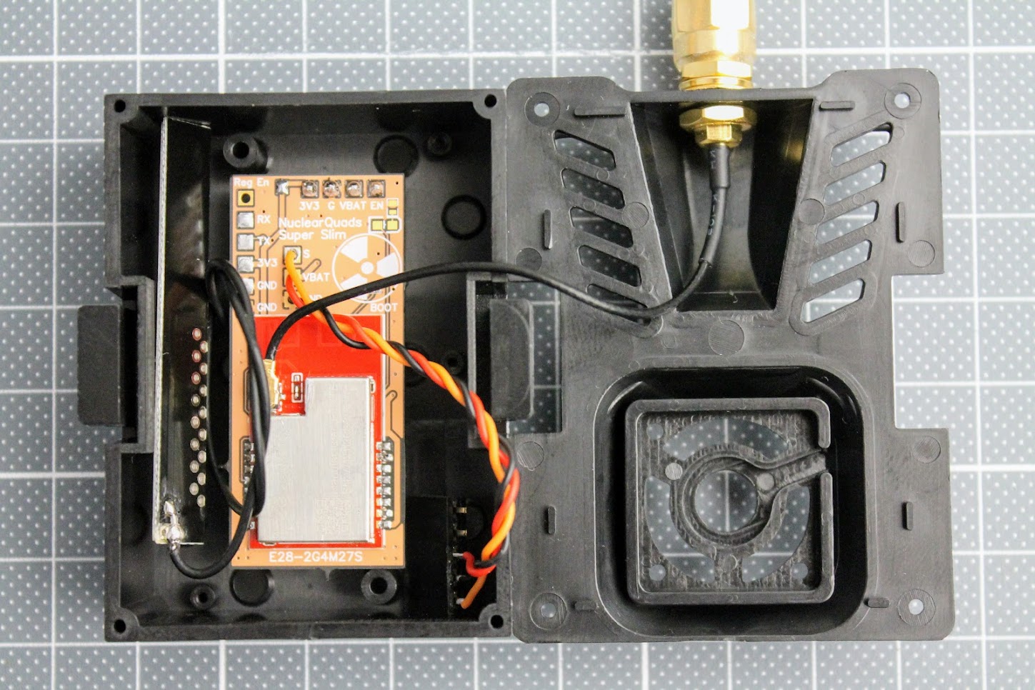
“Super slim” PCB variant of the ExpressLRS TX module fits easily in the JR case. Should also fit into the JR Nano case or even inside the radio as internal module.
Power output tests
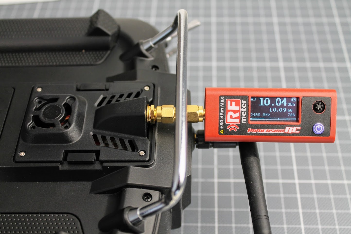
It is curious what RF power output does DIY ExpressLRS module gives. I have connected the ImmersionRC power meter to the antenna output of the DIY ExpressLRS module. The ExpressLRS module RF power output was set to 10mW, Dynamic power set to OFF. I’ve measured the exactly the 10mW of the power output.
At the 100mW output setting I’ve measured the 115mW output. 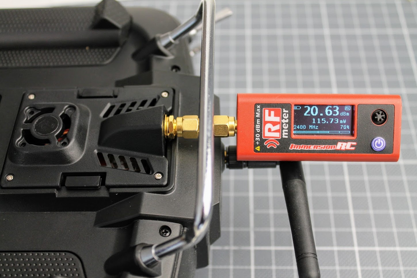
And at the 250mW?setting my RF power meter measured?255mW?of the RF output.?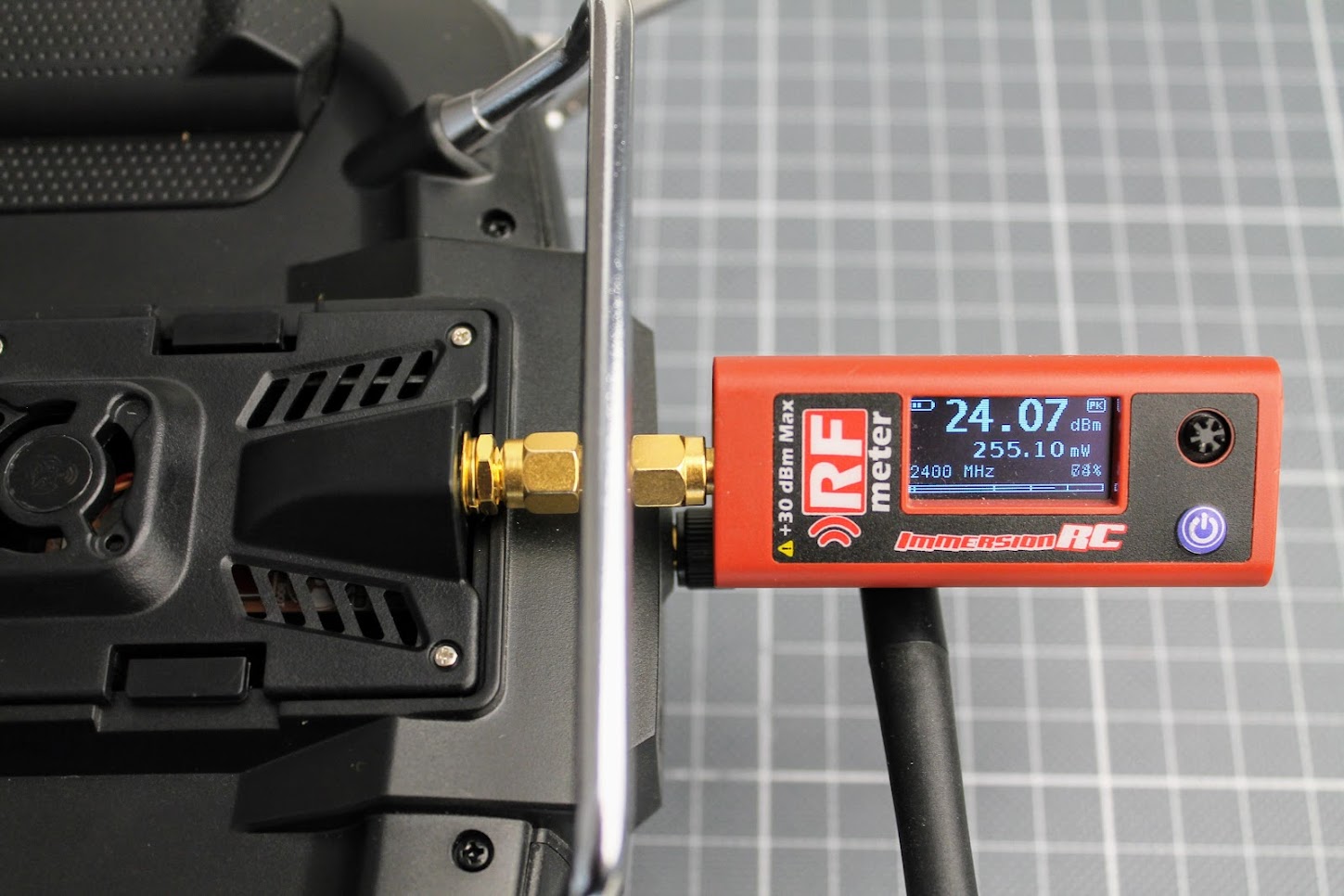
The 250mW output is stable, E28-2GM27S RF module does not heat up too much so no fan is needed.
?
DIY ExpressLRS Nano Receiver
Remarks
DIY ExpressLRS Nano receiver uses 0402 size components. They are small as 1.0 x 0.5mm (0.040″ x 0.020″). It is almost impossible or at least it is very hard to solder these components without hot air gun. You will need proper equipment and soldering skills for soldering this small RX.
RX Parts list
I have ordered the PCB on?OSH Park?(https://oshpark.com/shared_projects/yYtMC9D3).?The cost of PCB was $3.00?for 6pcs. That’s $0.5 for one piece. Cheap as beans.
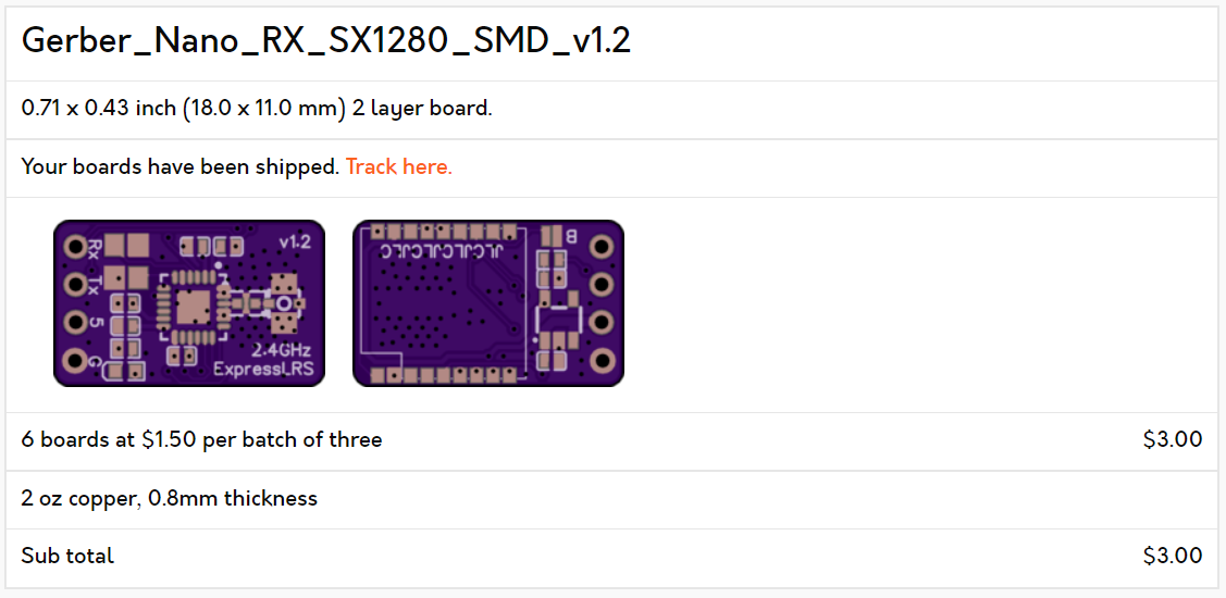
The original gerber files needed for PCB manufacturing can be found here: https://github.com/ExpressLRS/ExpressLRS-Hardware/…/PCB/2400MHz/RX_Nano
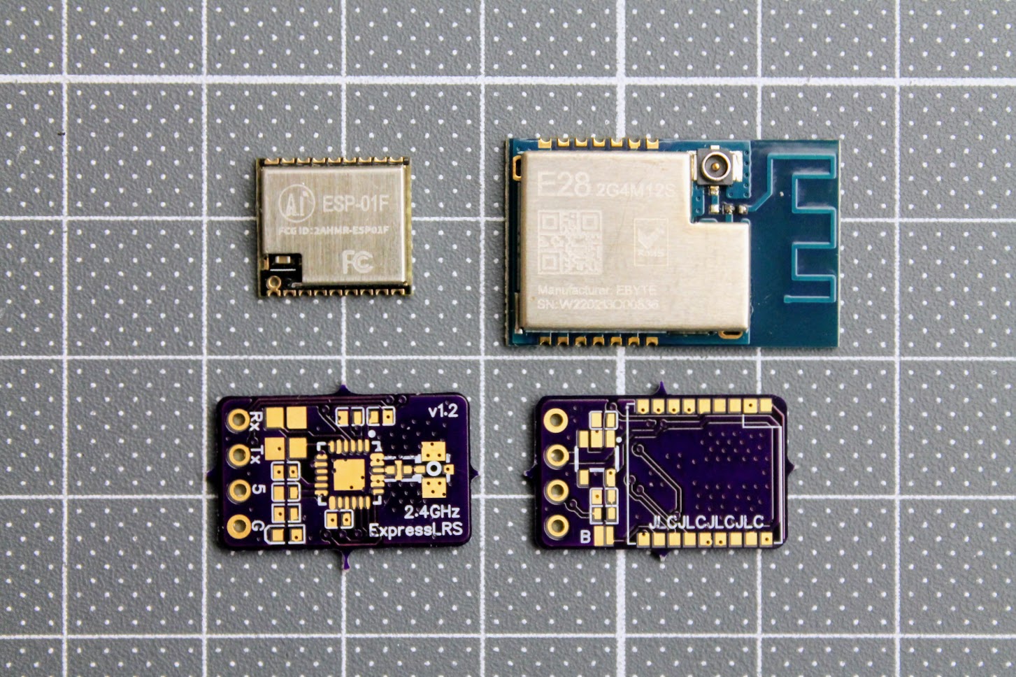
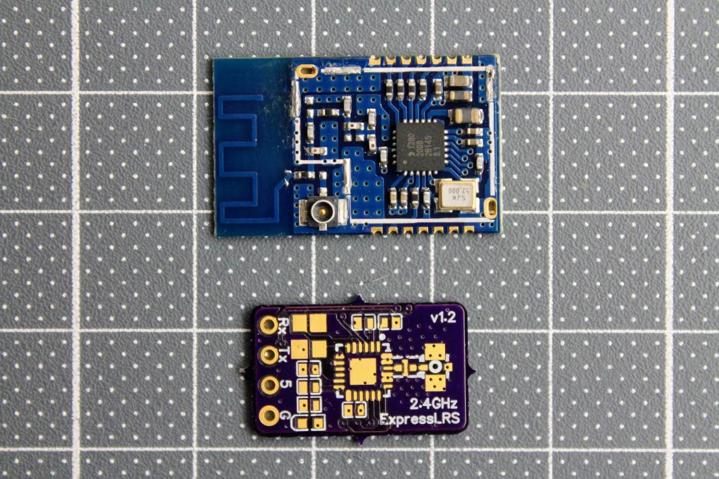
The EBYTE E28-2G4M12S module is used as the source for the cheapest SX1280 chip.?
EBYTE E28-2G4M12S on Aliexpress: https://www.aliexpress.com/item/1005001808615493.html
ESP-01F module – https://www.aliexpress.com/item/1005001808615493.html
Some 0402 size components
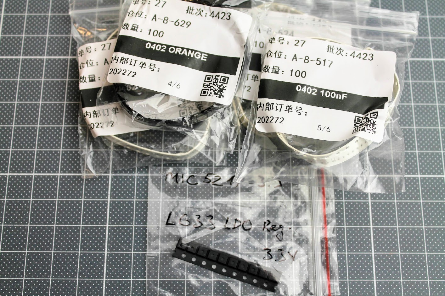
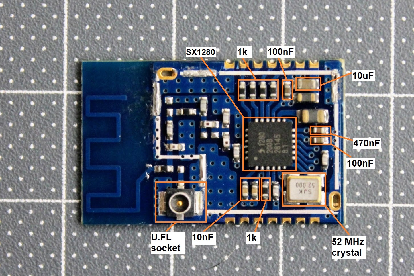
De-cased EBYTE E28-2G4M12S module.
Here is the diagram of the EBYTE E28-2G4M12S module components for reuse in ELRS receiver.
The only other components you need to get are:
0402 size LED diode, 0402 size 1uF and 2.2uF capacitors
MIC5219-3.3 or MIC5319-3.3 voltage regulator – https://www.aliexpress.com/item/33047428186.html
ESP-01F module – https://www.aliexpress.com/item/1005001808615493.html
2.4GHz low pass filter (ballun) – 2450FM07D0034T or 2450FM07A0029T. These are harder to get. Look for it on Mouser or DigiKey.
You will definitely need the RX antenna also.
Build process
The PCB and the components are so tiny, that you need definitely need the magnifying glass, hot air soldering gun, precision tweezers and SMD soldering paste. You will have to apply the soldering paste, place the SMD components on the back side of the receiver first, solder them with a help of hot air gun and then repeat the same on the top side of the receiver.
Photos of the soldered DIY ELRS Receiver.
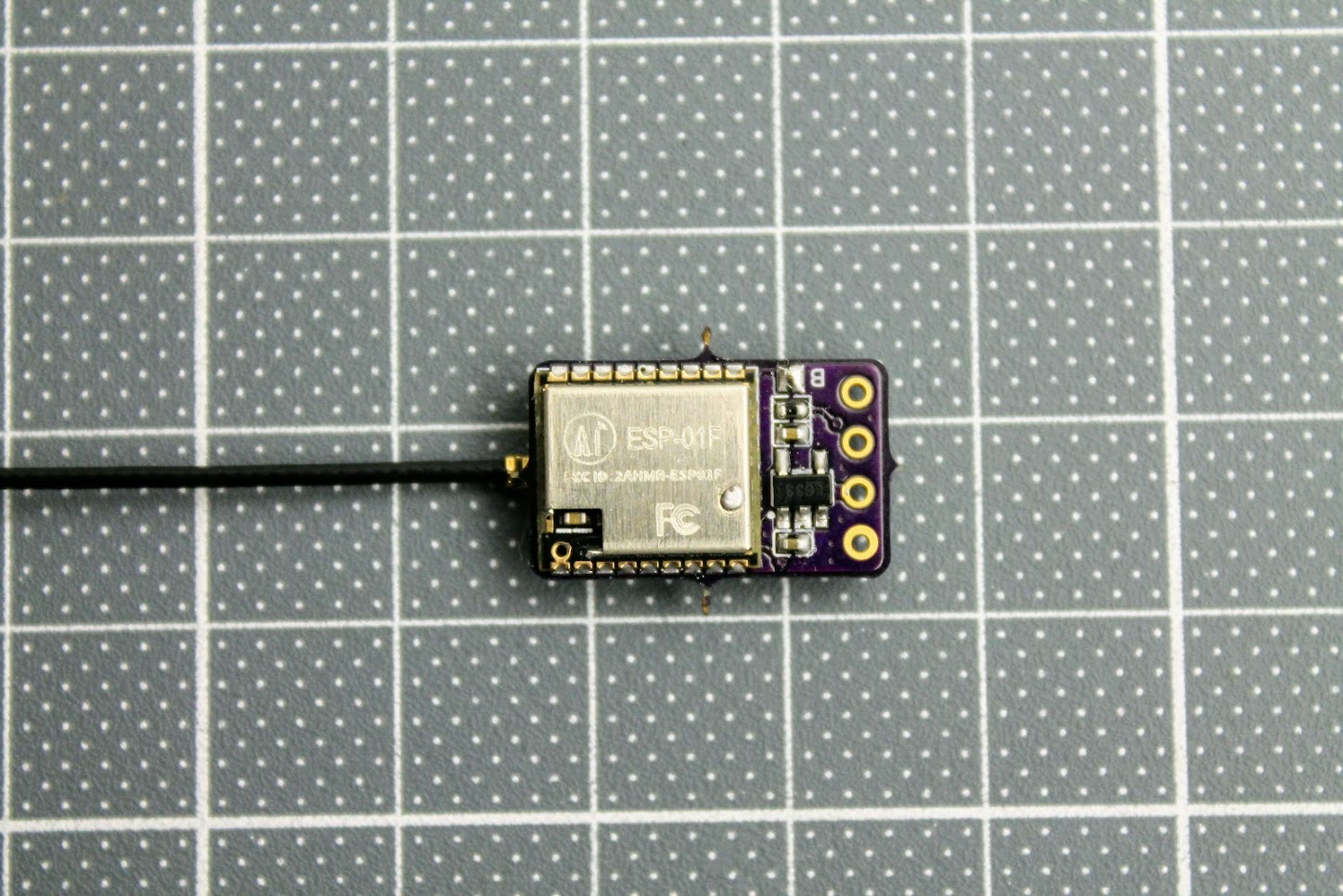
After the ESP-01F module is soldered, you need to solder the RX, TX, 3.3V and GND wires. Connect these wires to the corresponding pins on the FTDI or any other USB to serial adapter. You can also use Arduino Uno board for USB to serial adapter. Don’t forget to short the BOOT pads on the RX board for flashing the firmware by UART.
Read more about the flashing the ExpressLRS here:
ExpressLRS Open Source Long Range radio control system – Complete Guide
DIY ExpressLRS receiver ready for flashing.
Making the ExpressLRS transmitter and receiver by yourself is definitely a fun task, however you should evaluate your skills of the SMD soldering in case of the making the super small receiver.
]]>
Features and specifications
- EdgeTx / OpenTX Firmware
- Hall Sensor Gimbals
- Two options: internal CC2500 JP4IN1 Multi-Protocol Module or internal ELRS Module
- Jumper AION ELRS, TBS Crossfire Nano & ImmersionRC Ghost module support
- USB-C Charging
- Voice & Vibration feedback
- Frequency: 2.4GHz ISM
- JP4IN1 Version RF Chipsets:
- A7105 for Flysky,Hubsan,AFHDS2A etc
- CC2500 for Frsky, Futaba SFHSS, Hitec, Radiolink, Esky etc
- CYRF6936 for DSM / DSMX,Walkera Devo,Wfly etc
- NRF24L01 for HISKY,Syma,ASSAN etc
- ELRS version:
- RF Output Power: 10mw/25mW/50mW/100mW/(
150mW) - Packet Refresh Rate: 25Hz/50Hz/100Hz/250Hz/500Hz/1000Hz
- RF Output Power: 10mw/25mW/50mW/100mW/(
- Full-size adjustable hall sensor gimbals
- 1.3 ” LCD screen, resolution 128*64
- OpenTX/EdgeTX native support
- Voice and Vibration function
- Input Voltage: DC 3.5-4.2V
- Battery: 1×18650 Li-ion cell (Battery not included, needs button top 18650 battery as flat end batteries are too short)
- USB Type-C internal charging
- Support External module including Full Power Jumper AION ExpressLRS External Module and TBS Crossfire module
- 16 Channels
- Micro SD Card included
- Link Range: >5KM
- Size: 166x106x56mm
- Weight: 207g
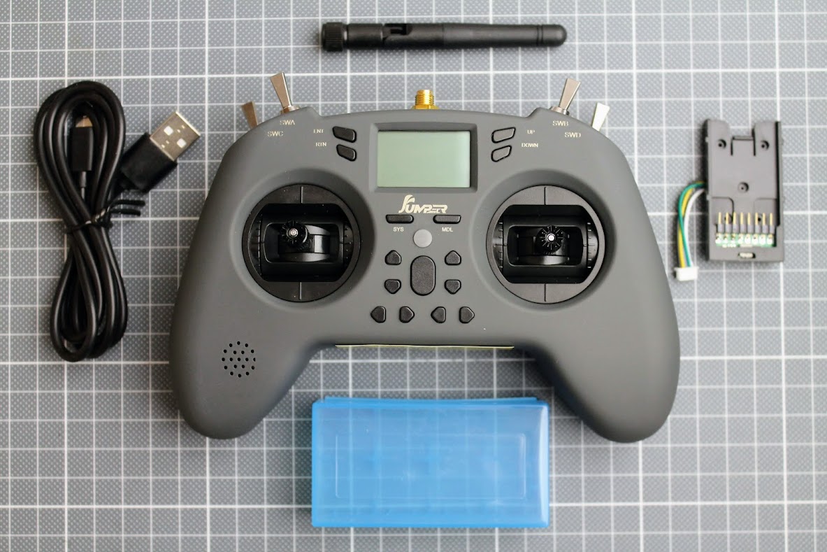
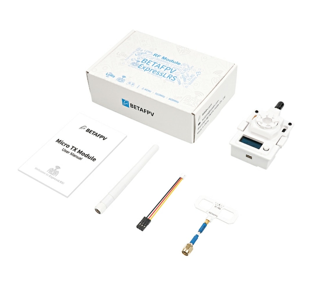
Package contents
You will get the T-Lite V2 radio, Antenna, USB Type-C cable, external nano sized module bay and a case for two 18650 batteries.
T-Lite V2 differences from V1
- The power supply circuit improved
- The main MCU was changed
- The internal ELRS module option
- Power led indicator changed
- Slightly brighter color
More on each of the changes are described below
Closer look
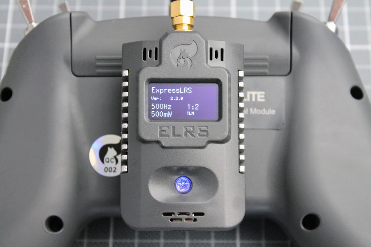
Radio hasn’t changed much. The only visible changes – radio power indicator led was changed to the led with less brightness and the T-Lite V2 has slightly brighter gray color.
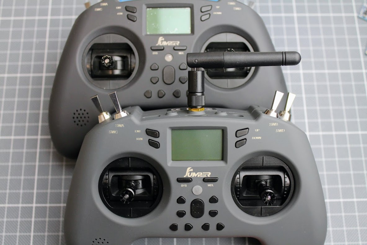
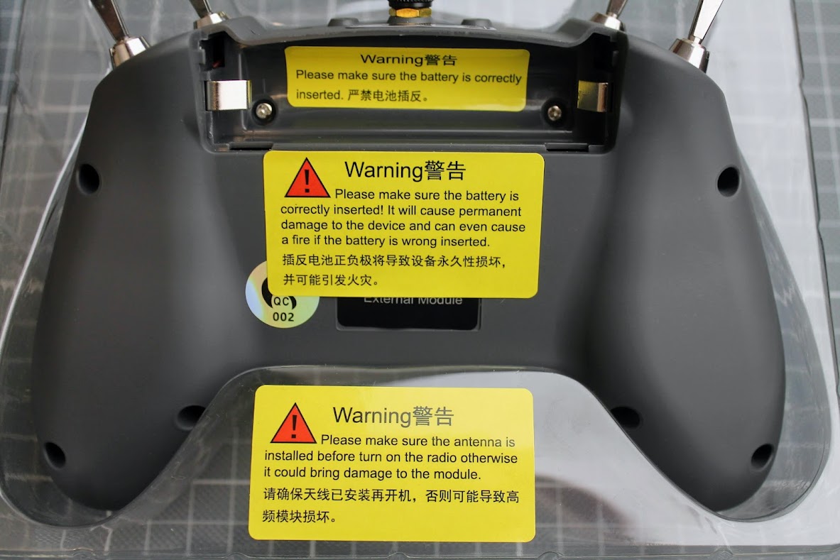
A lot of warnings on the stickers.
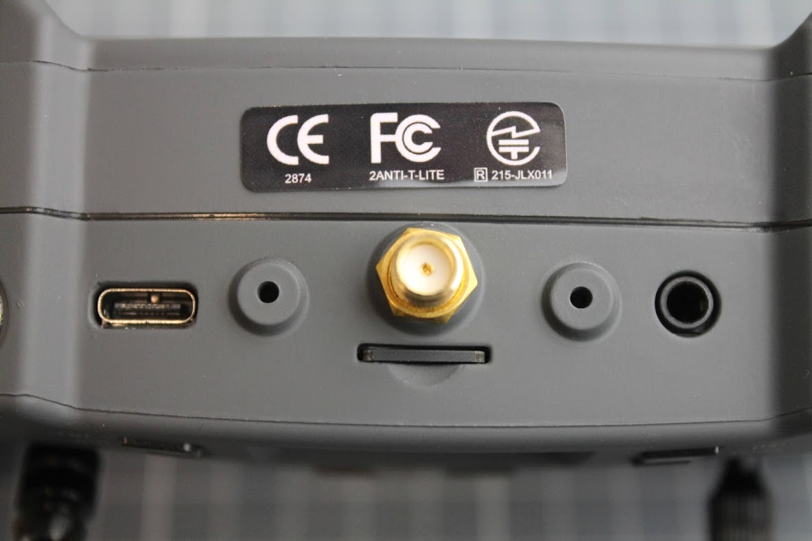
On the top side of the radio you will find the same USB Type-C and trainer sockets. Also the SD card slot with preinstalled SD Card and SMA type antenna connector.
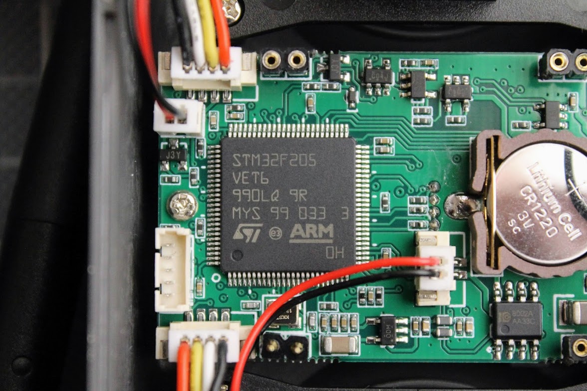
Inside the radio
Inside the radio you will find the same hall effect gimbals, switches, nothing has changed except the main board.
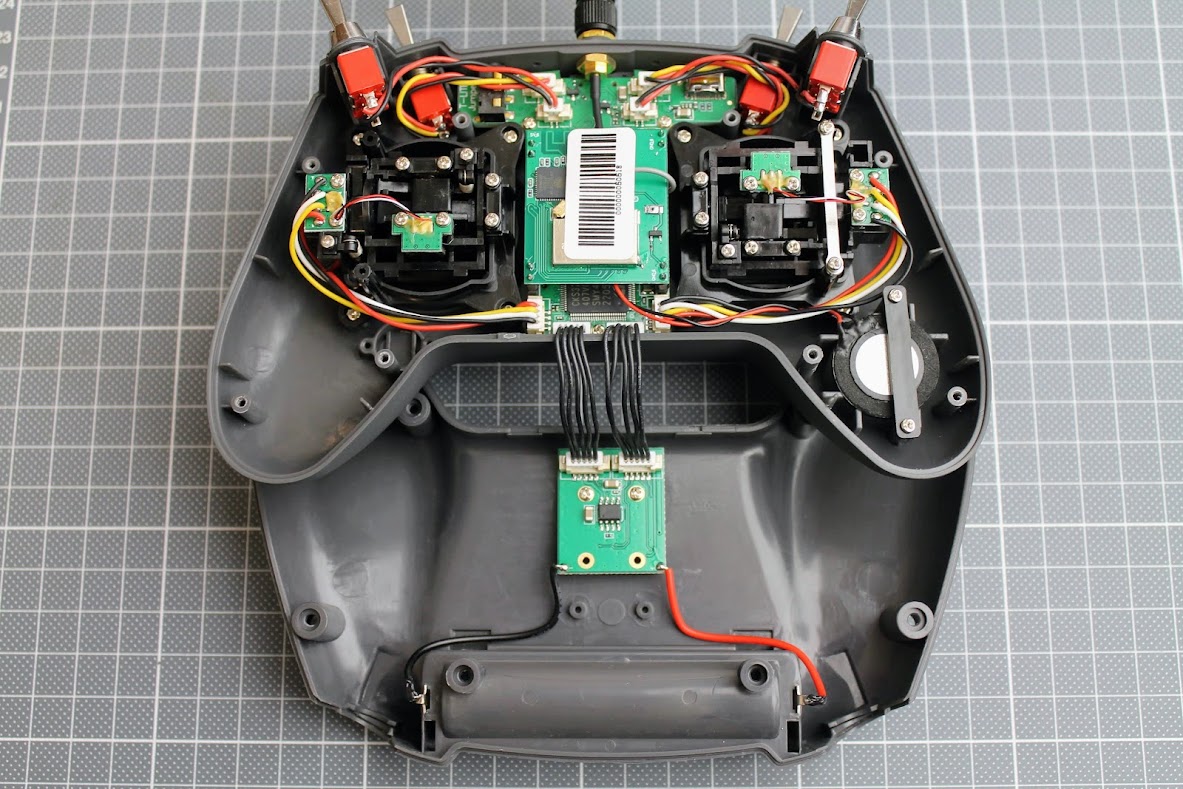
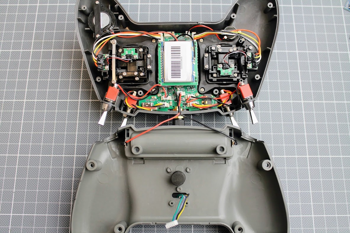
The main board was redesigned. The changes are mainly for the power supply part of the radio.
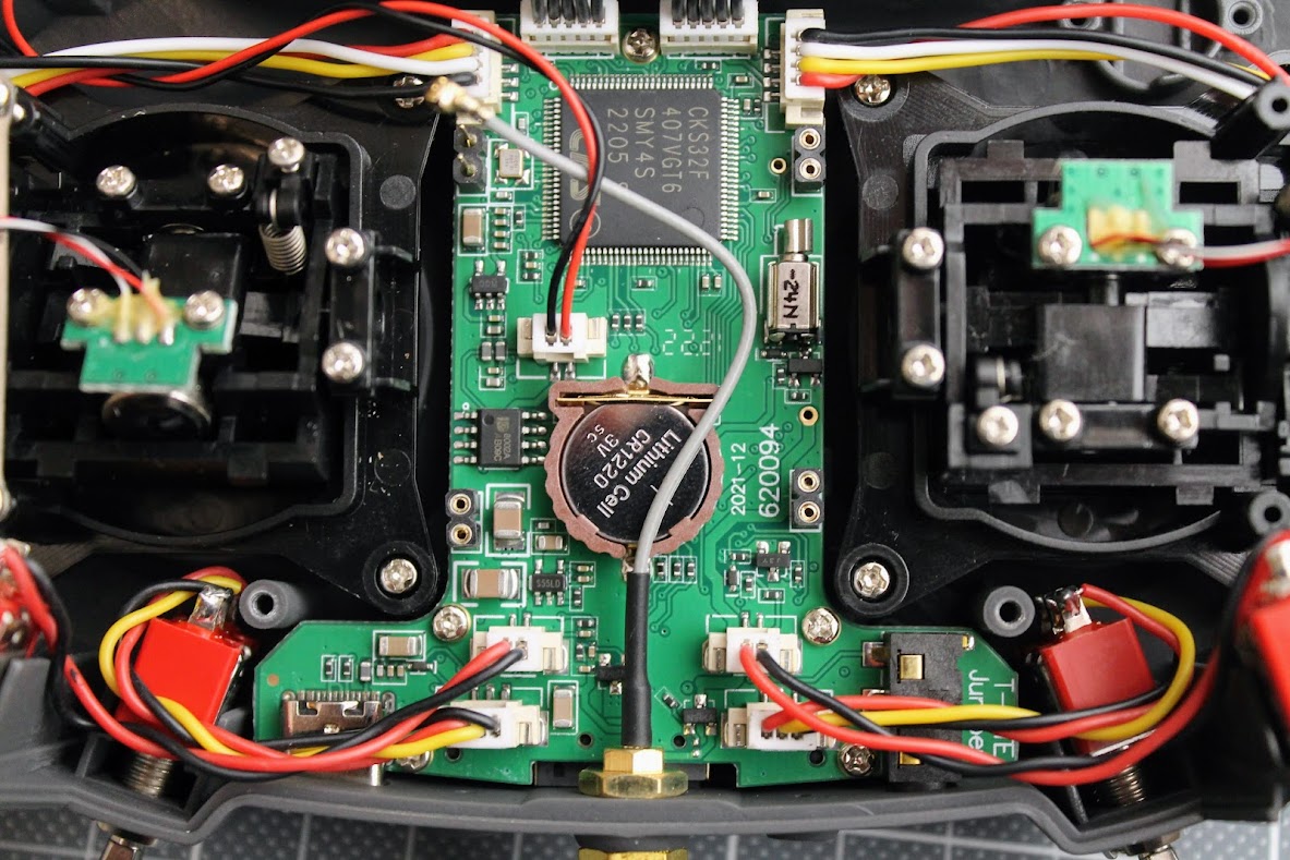
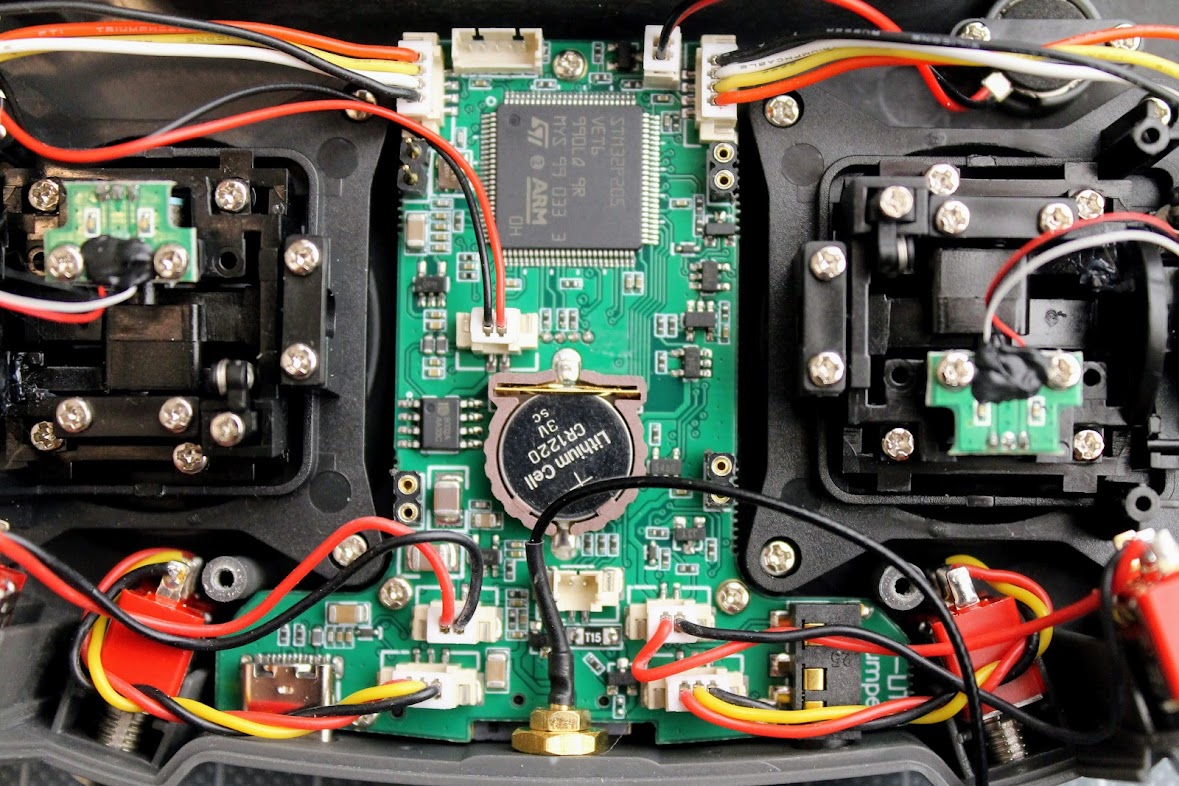
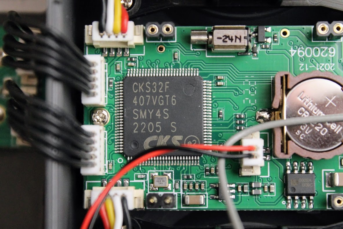
The main MCU was changed from STM32F205 to some cheaper cloned CKS32F407 MCU. Probably the chip shortage and skyrocketed prices influenced it. While it is cheaper MCU (cloned from STM32F407VGT6) it has ~25% faster clock speed and twice more the flash size (1 Mb compared to 512 Kb). So faster and bigger is better.
T-Lite V1
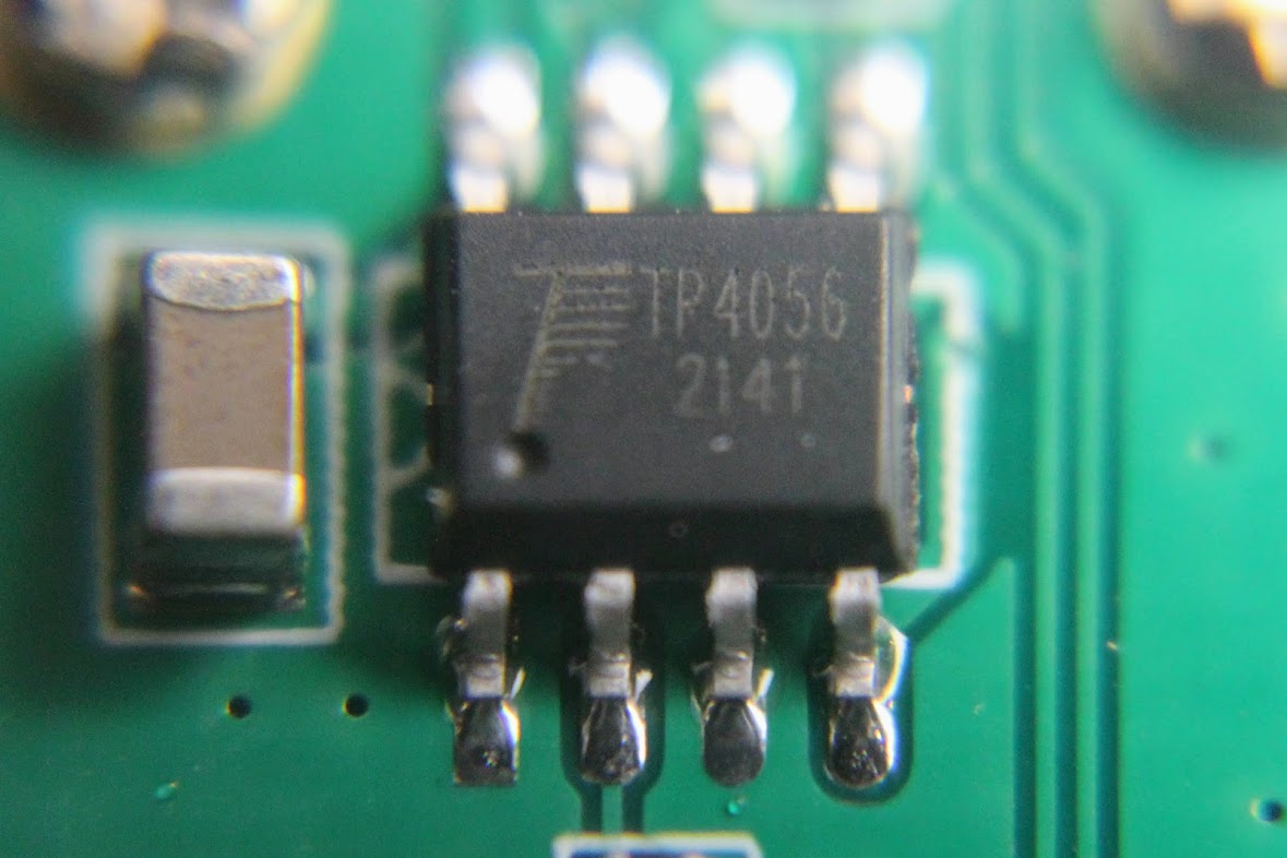
The lion battery charging circuit is located on the separate PCB which also populates the external module bay connector.
The battery charging process is controlled by simple and widely popular TP4056 IC.
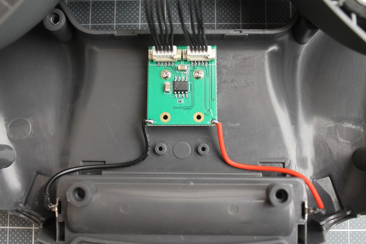
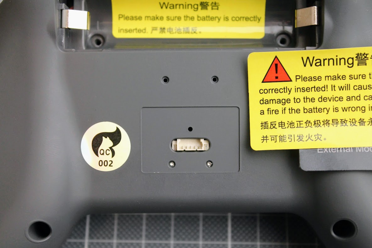
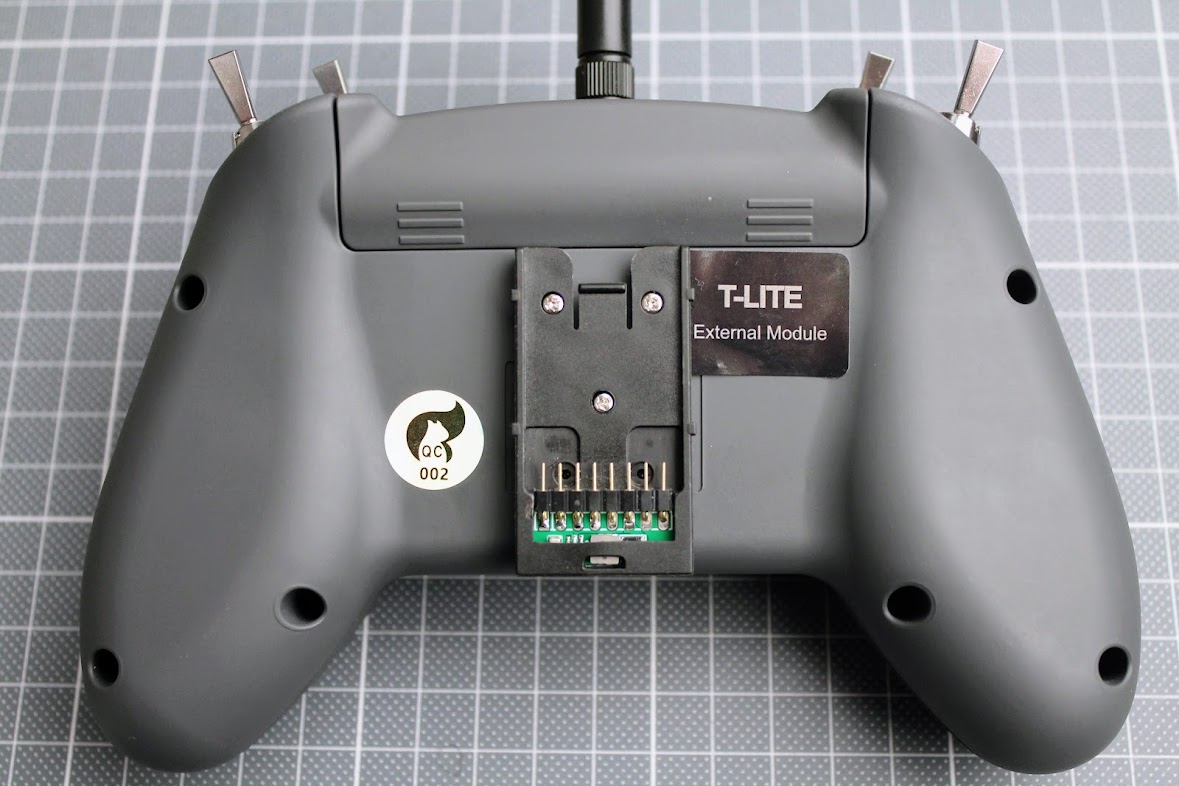
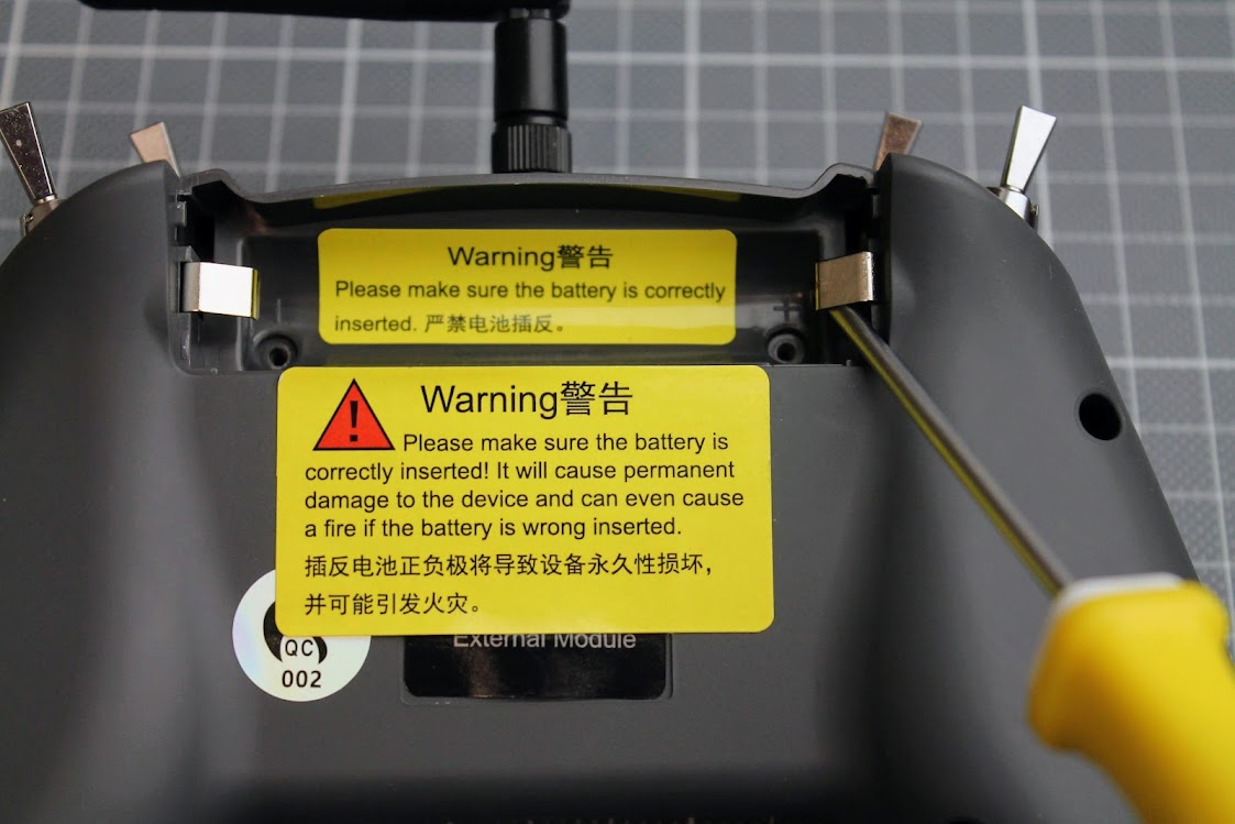
External module bay
External module connector is hidden under the sticker on the back side of the radio. This connector was inaccessible from the outside in the T-Lite V1 and required opening the radio in order to connect the external module cable to the radio mainboard. You don’t need to to open the T-Lite V2 and it makes the installation of the external module bay much easier.
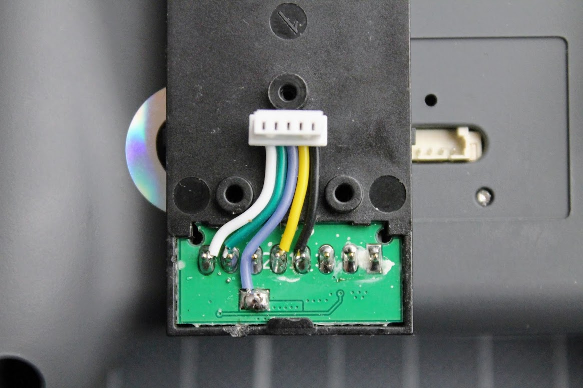
The external module bay connection cable lengh was ok for the T-Lite V1 radio, as the connector was inside the radio and mosto of the cable stays inside. However on the T-Lite V2 this connector cable is way too long and stick outside.
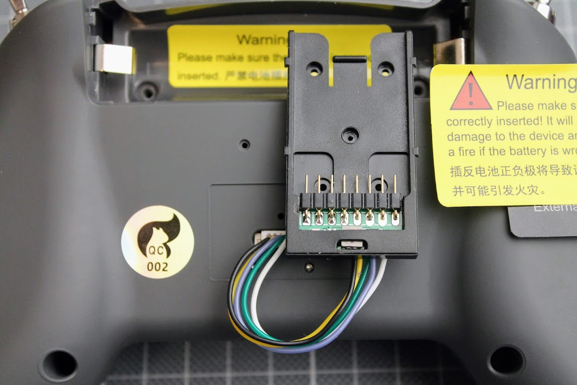
I had to trimm and solder the wires to make the cable shorter.
Clear and neat installation – no cables are seen.
The power supply in the T-Lite V2 is capable of providing the enough current to the higher power external modules. Quick test with Jumper AION TX module on 500mW setting confirmed if – no problem with power supply. It was unable to use power hungry external TX modules on the T-Lite V1 – not enough current and modules were tending to shut down.
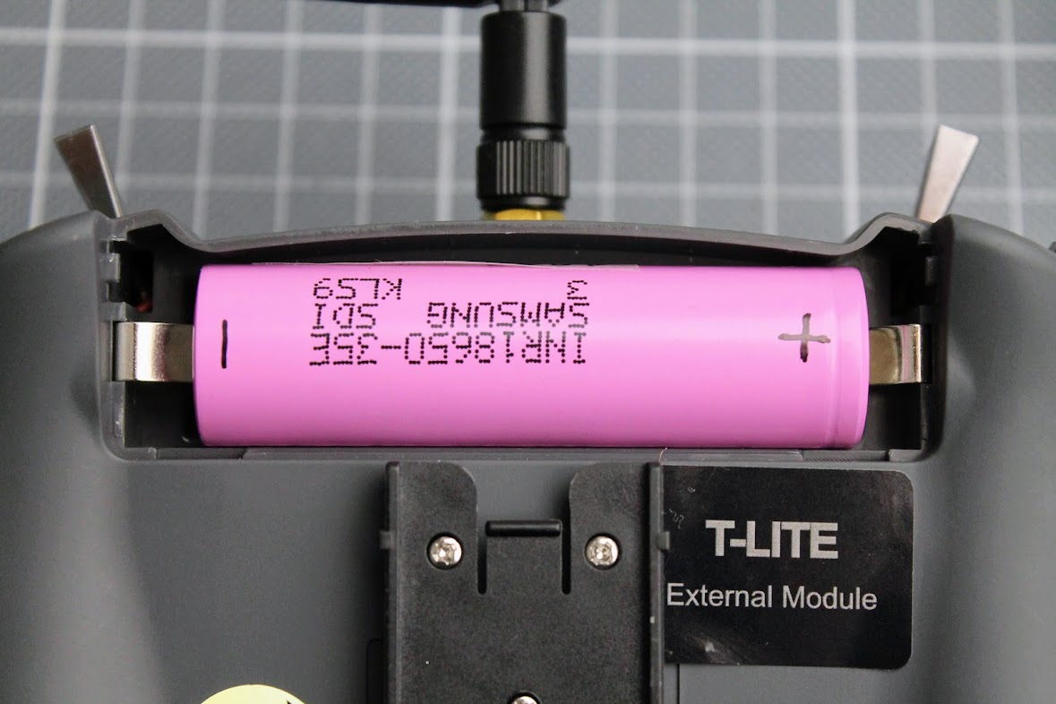
Battery notes
Jumper T-Lite radio is designed to use the lion 18650 batterie with the button top.
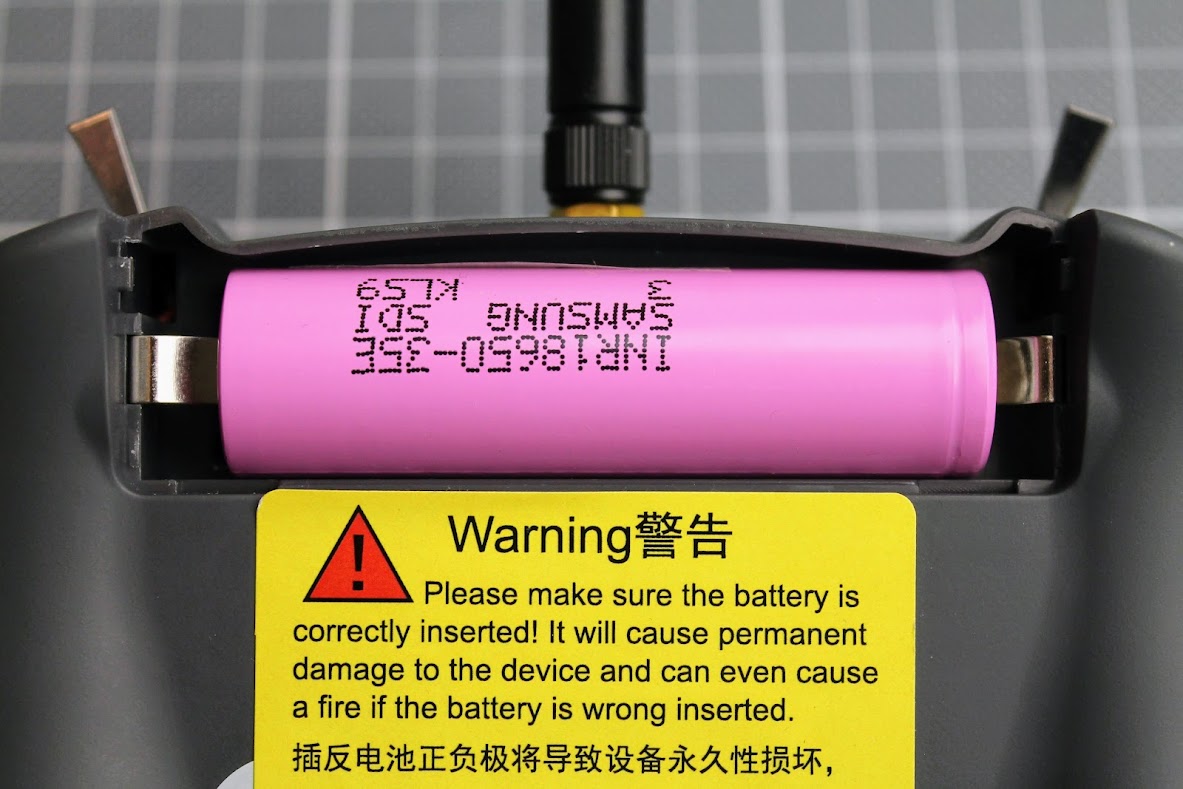
Simple hack enabling to use the batteries with flat ends is to bend the battery tabs inwards. After this small mod you can use the most common lion 18650 batteries with flat end.
I also marked the polarity of the battery with a marker to make sure it is installed in correct way. There is a warning sticker saying that inserting the battery in reverse polarity will damage your devce. I have accidentally inserted the battery in reverse several times, however it did no harm to the T-Lite V2 radio.
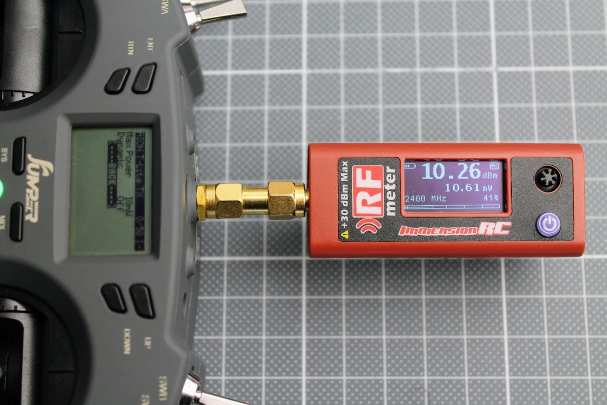
RF power output test
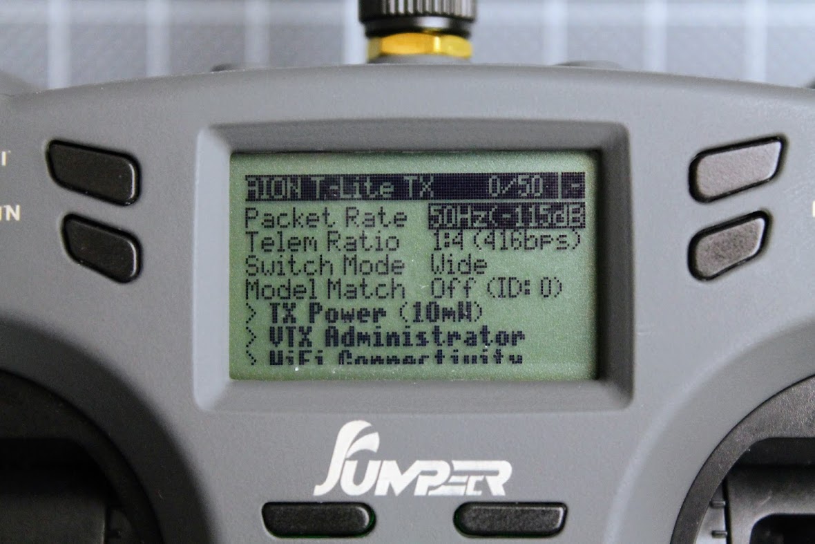
I have testedthe RF power output of the Jumper T-Lite V2 ELRS Radio. On the 10 mW setting (Dynamic power set to OFF) it outputs almost exactly the 10 mW
On the maximal 100mW power setting (Dynamic power set to OFF) radio outputs 124 mW.
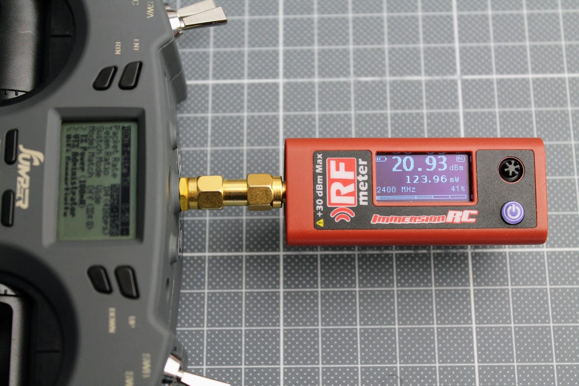
There is no 150 mW output setting in the ELRS firmware for the Jumper AION T-Lite ELRS module despite the specifications on the Jumper website.
T-Lite V2 internal ELRS module firmware upgrade
The T-Lite ExpressLRS TX module can be upgraded by WiFi, EdgeTX passthrough or UART. WiFi and EdgeTX passthrough are recommended as UART method requires additional hardware and is the most complicated one.
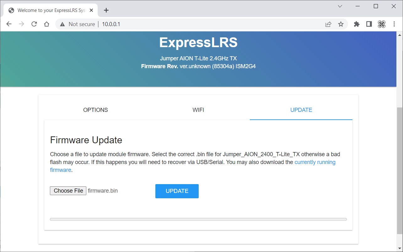
Upgrade by WiFi
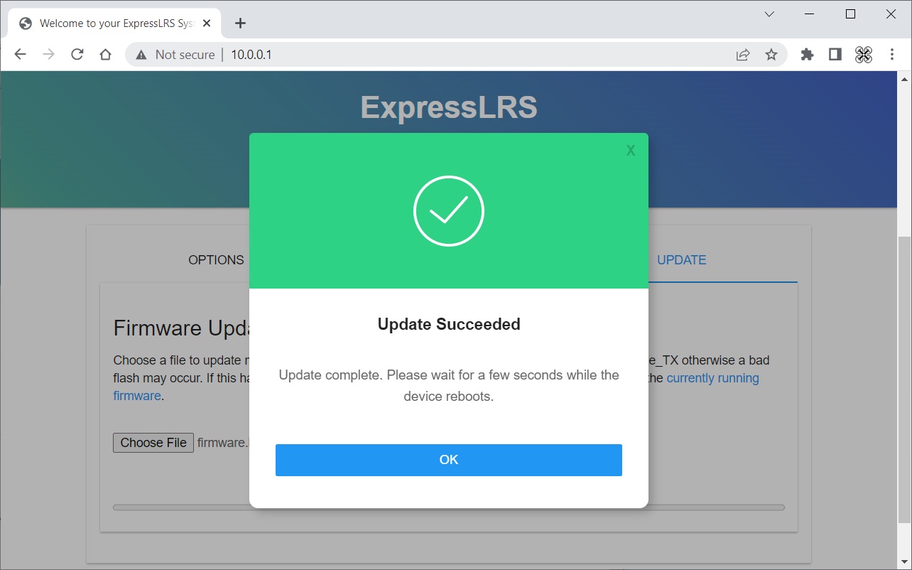
Go to ExpressLRS LUA script on the radio, select WiFi connectivity and enable WiFi. Then open the url http://10.0.0.1 on your web browser. Select the UPDATE tab and choose firmware file.
Hi the update button and wait for the firmware to update.
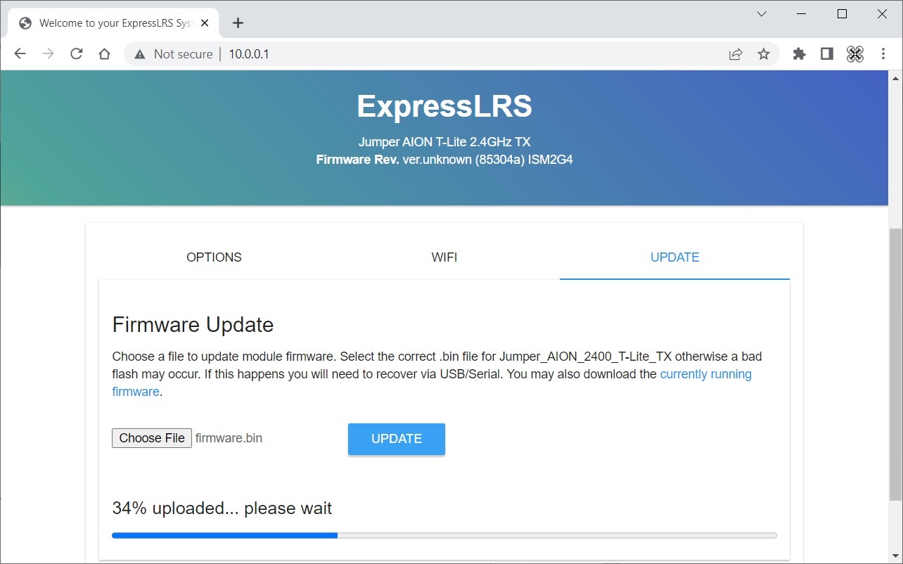
ExpressLRS firmware successfully updated!
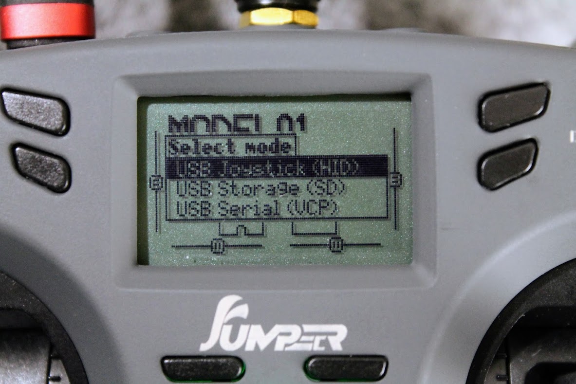
Update by EdgeTX serial passthrough
EdgeTX has ability to connect directly to the internal TX module. This is called EdgeTX serial passthrough. It can be enabled by connecting the radio to the PC by USB TypeC cable and selecting the “USB Serial (VCP)” option in the popup menu on the radio.
After this you should see the Serial port device in the Device manager, however it didn’t worked on my pc at first. All I could see were some Jumper TLite Serial Port and USB Serial Device with exclamation marks, meaning that these devices don’t work properly or the device drivers are incorrect.
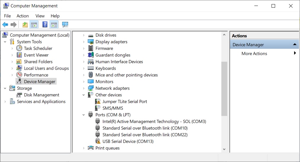
I downloaded the STM32 virtual serial port drivers from the STM32 MCU manufacturer website. Here is the link (or you can google it): https://www.st.com/en/development-tools/stsw-stm32102.html
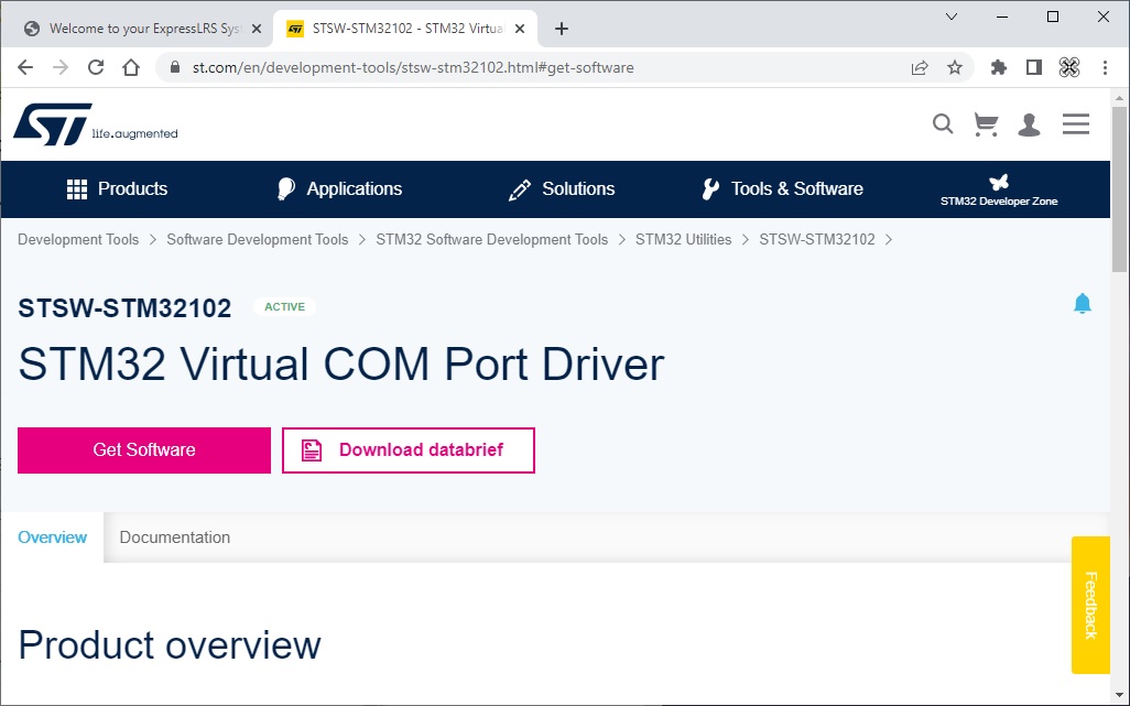
After I installed the driver it worked like charm. Now I can see the STMicroelectronics Virtual COM Port device in my Device Manager.

Once your T-Lite Radio EdgeTX serial passthrough is working, you can open the ExpressLRS Configurator and select the EdgeTxPassThrough as Flashing method.
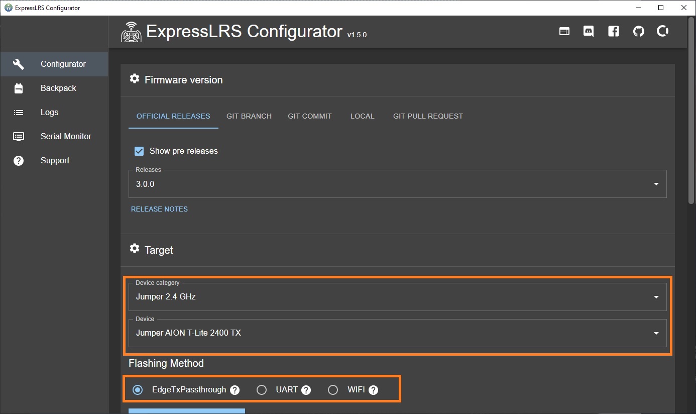
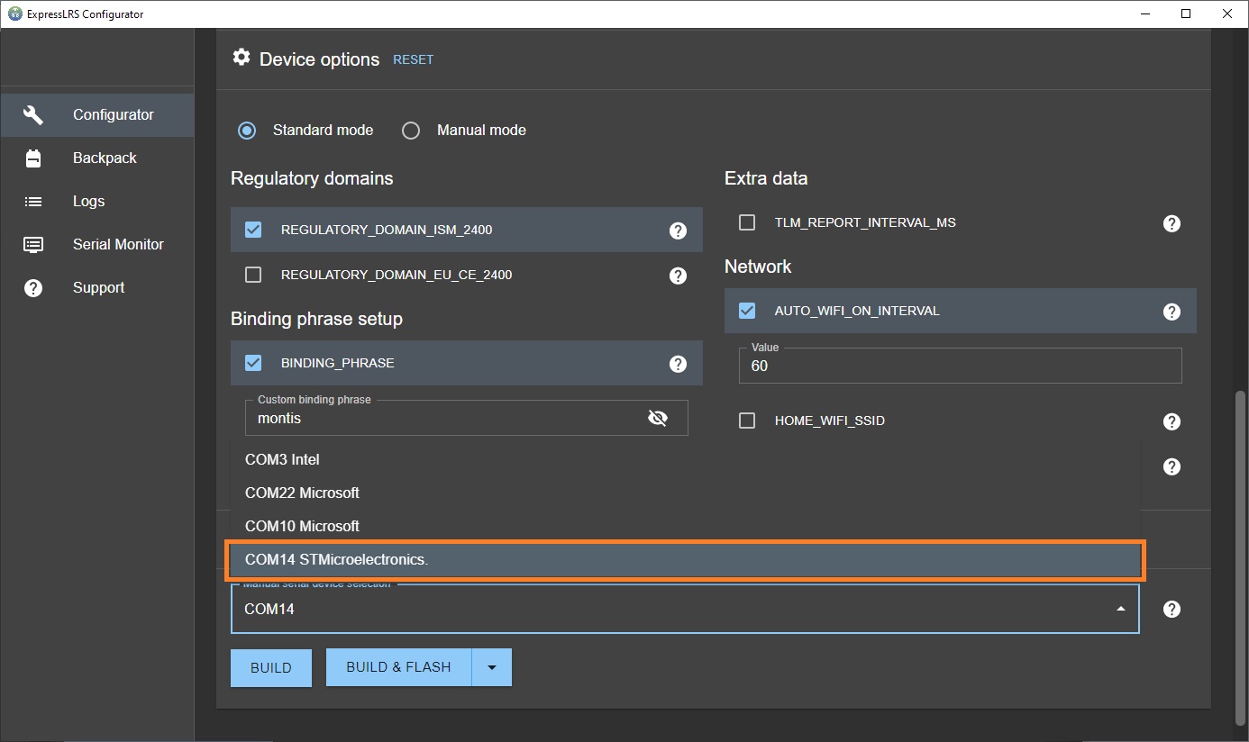
Choose COMxx STMicroelectronics as serial port from the drop down below. Hit the BUILD & FLASH button and wait for the firmware to be updated.
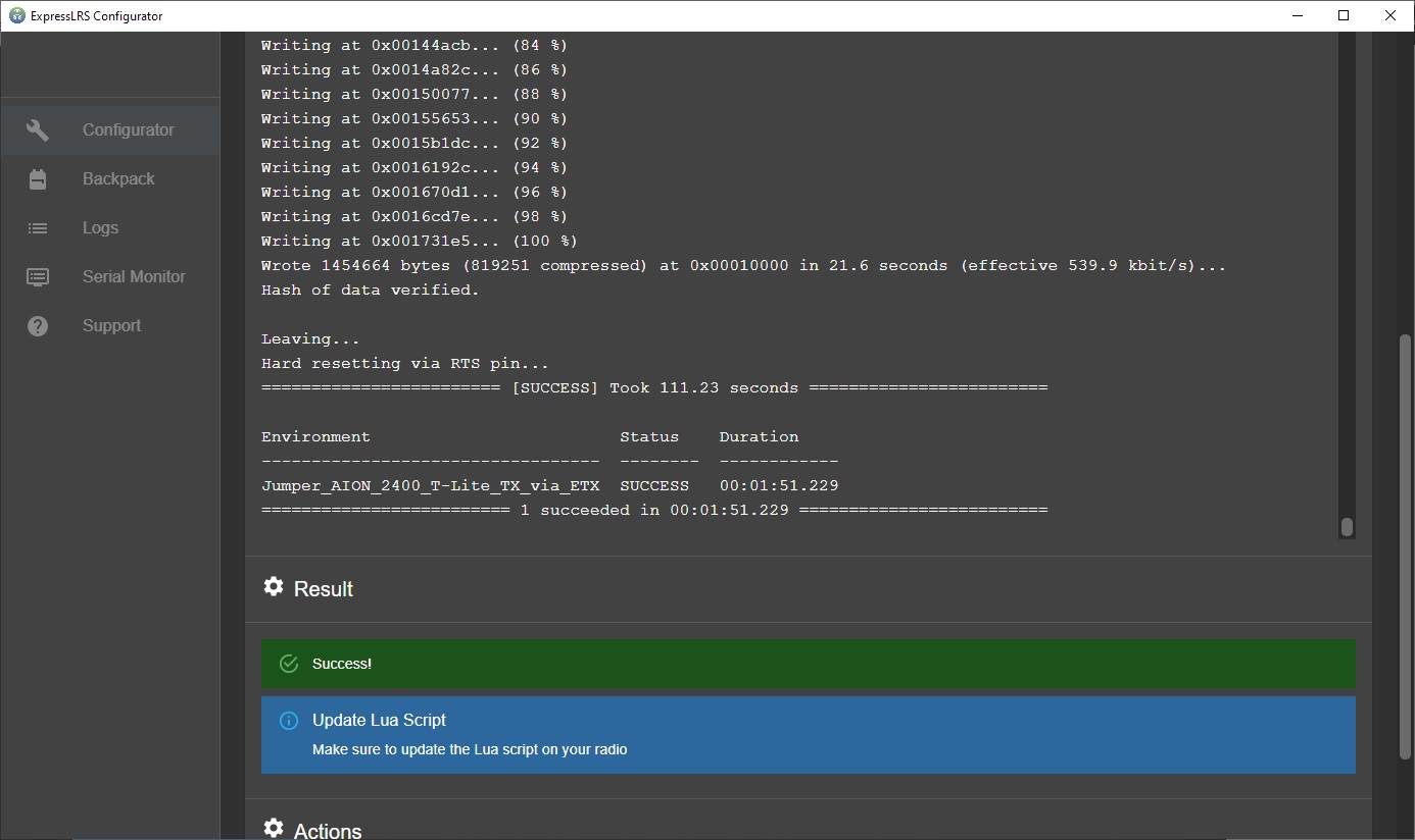
ExpressLRS firmware successfully updated.
Don’t forget to download the newest ExpressLRS lua script after the TX module update. Especially if you are upgrading from the versions 1.0 or 2.0. You can download the Lua script from here https://github.com/ExpressLRS/ExpressLRS/tree/master/src/lua or from the ExpressLRS Configurator.
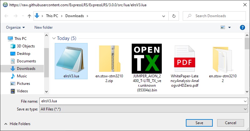
Place it on the radio SD card folder \SCRIPTS\.
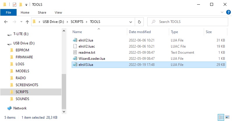
ExpressLRS Lua script in action.
Things I don’t like
The menu navigation buttons are definitely too small. Unfortunately this is due to the extremely compact radio size. Actually the radio is so small that sometimes I wish it was just a bit bigger.
I would swap the upper three position switches with the lower two position switches as I use the top one for arming and the two position is just enough for this task.
Things I like
T-Lite is the most compact full featured OpenTX/EdgeTX radio in the market. I really like it’s compact size and from. It is very convenient to carry this radio in the backpack. T-Lite is half the size of the full sized radio.
Only one Lion 18650 battery is needed and it lasts for hours. You can also bring another one for the backup battery.
Jumper T-Lite V2 can be purchased from:
Banggood: https://www.banggood.com/JumperRC-T-Lite-V2-…-Radio-Transmitter-for-RC-Drone-Airplane-p-1959513.html
Disclaimer: This item was supplied by Banggood for a fair and unbiased review. Banggood never asked for a positive review and never influenced my opinion in any way. I’m trying my best to stay uninfluenced and give you only my own opinion. All affiliate links, if there are any, help me purchase items for reviews and tests.
]]>
Video from iFlight:
Update 2022-04-11:
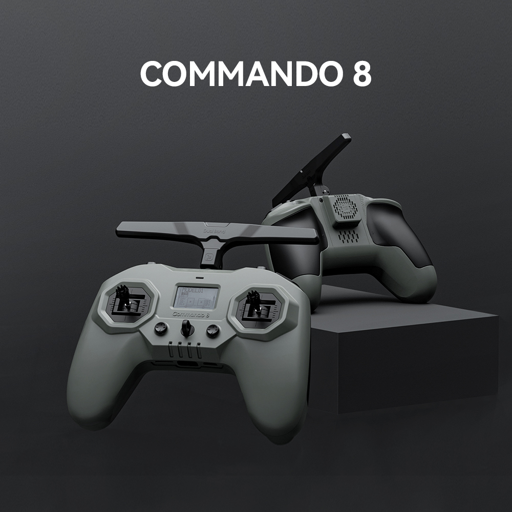
iFlight has upgraded Commando 8 ELRS radio: upgraded circuits and gimbals, added a speaker and some other improvements. Also developed a Nano module bay upgrade for modules like the TBS Crossfire. The power supply for external module supports modules with?1W.
Available @:
iFlight:?https://shop.iflight-rc.com/Commando-8-Radio-Transmitter-Pro1696
Banggood: https://www.banggood.com/IFlight-Commando-8-ExpressLRS-ELRS-…-1925414.html
Specifications:
Item: Commando 8 Radio Transmitter
First module: Frsky D8/D16 and Futaba Multiprotocol transmitter
Supported Protocols: Futaba S-FHSS/Frsky D16/Frsky D8
Second module: ExpressLRS 915MHz or 2.4GHz (inbuilt in back of the radio)
2.4GHz system: CC2500/SX1280
915MHz system:?SX1276
Antenna:?Dual-Band Antenna (915MHz+2.4GHz)
RF Power:
ExpressLRS 2.4GHz: 10-25-50-100-250-500mW
ExpressLRS 915MHz: 100-250-500-1000mW
D8/D16: 100mW
Channels: 8
Mini High Precision Hall Gimbal
Support TYPE-C 20W Quick Charge / Firmware Update
Battery: Built-in 4000mAh 1S2P 18650 Battery
Charging Connector: Type-C
Weight: 310g
2022-04-11: Updated radio revision
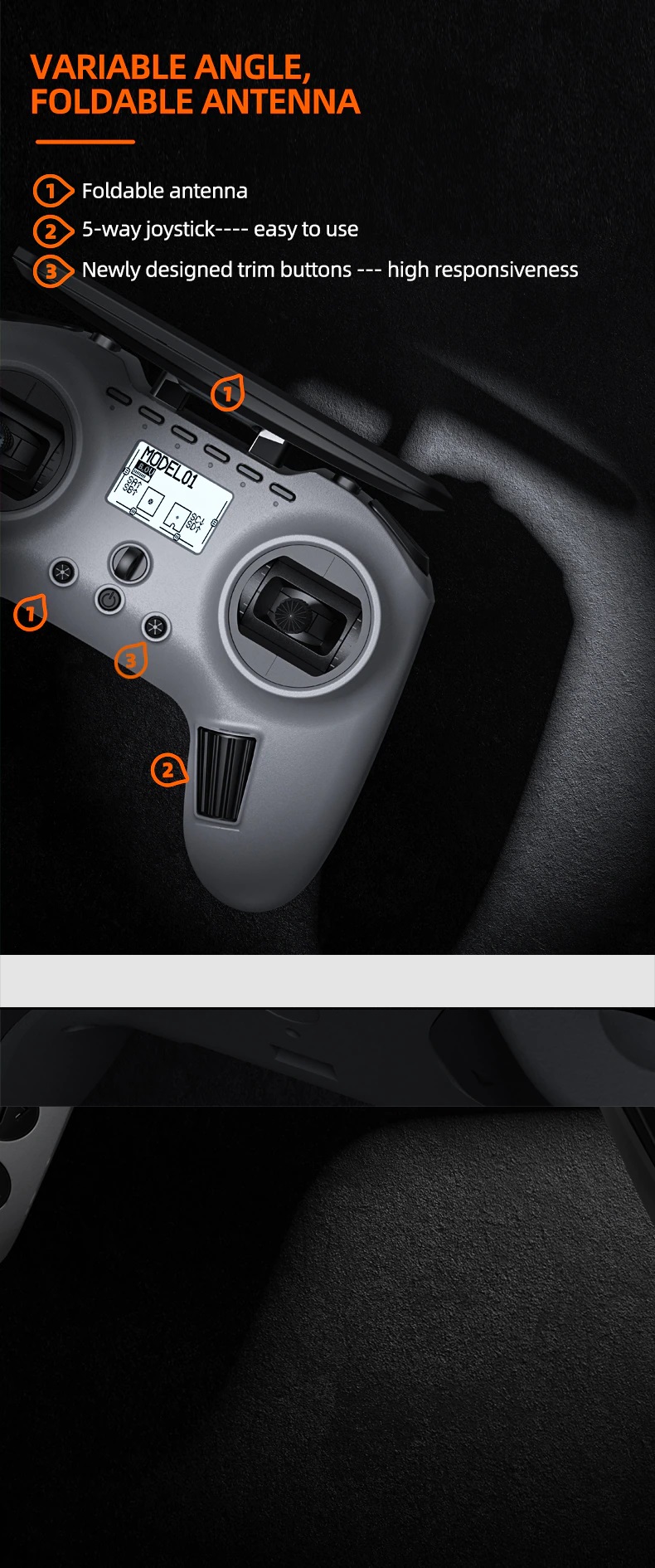
]]>It will have internal 4-in-1 multiprotocol?at first and then version with?internal?2.4GHz ExpressLRS modules will be released with foldable and non removable antennas that can’t be oriented vertically (be the way, the recommended position of the dipole antenna should be vertical)
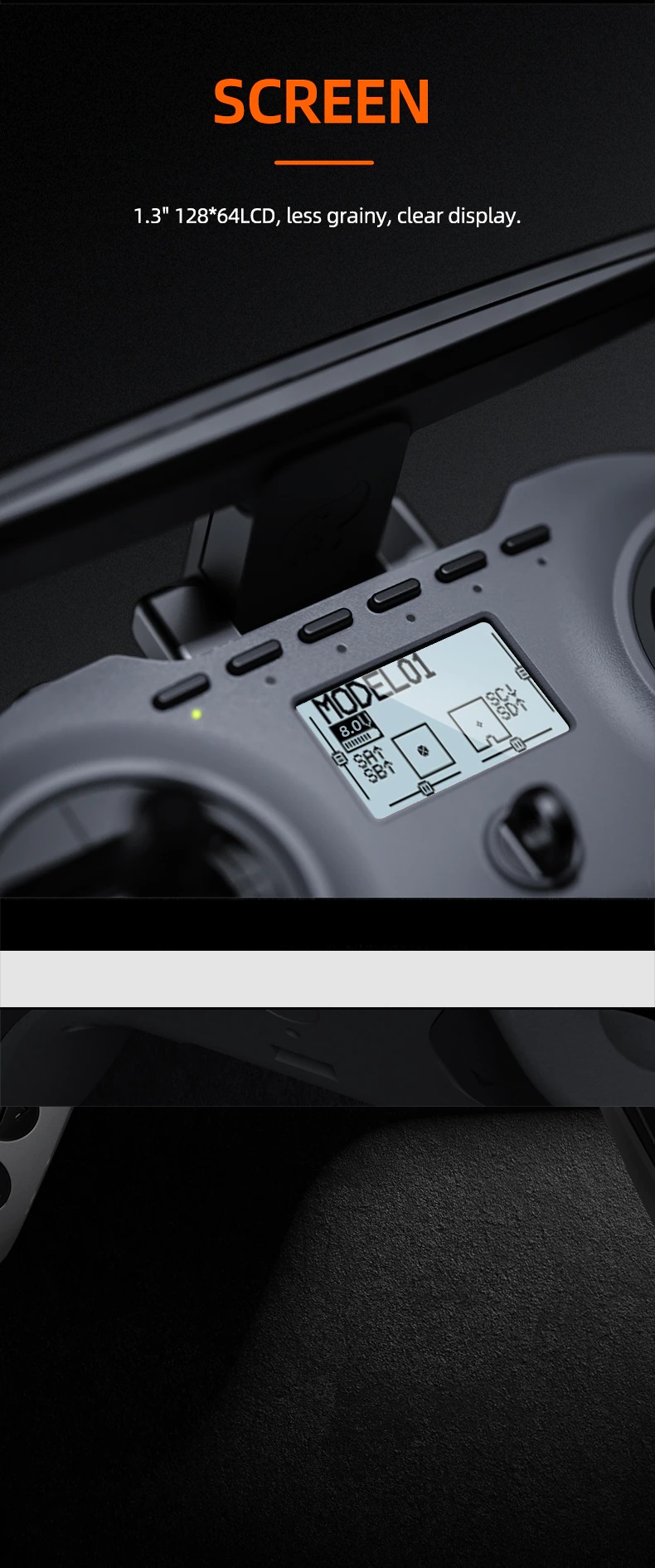
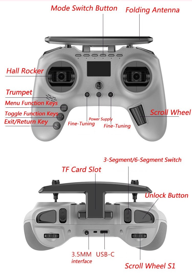
Jumper T-Pro will have the same gimbals as on the Jumper T-Lite radio, navigation scroll wheel as on?TBS Tango 2 and three buttons for menu control. There are two trimmer joystick switches and the neck strap hook in the middle. 6-pos push buttons are located on the top side of the radio. T-Pro is equipped with 128×64 monochrome LCD screen.
There will be two 3-pos toggle switches (similar as on TBS Tango 2), two momentary switches and two scroll wheels.
Jumper T-Pro will have JR Lite (Nano) TX module slot for Multiprotocol, ExpressLRS or TBS Crossfire/Tracer modules.


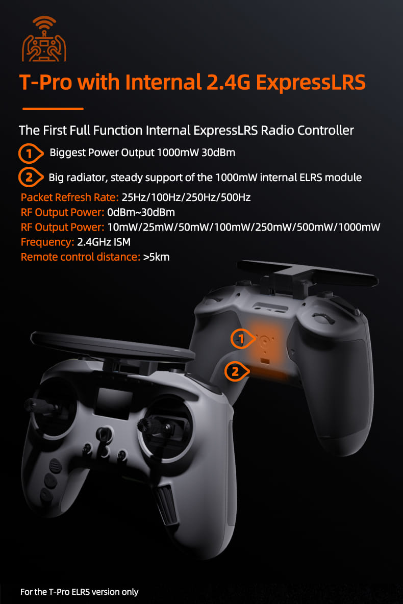
There is also Jumper T-Pro version with integrated ExpressLRS module. Up to 1000mW (30dBm) of RF power output.
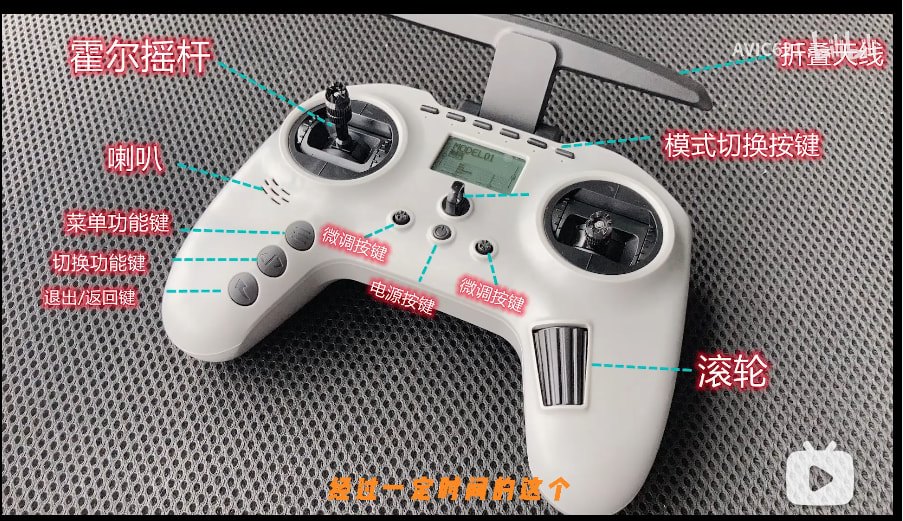
Jumper T-Pro switches and buttons layout diagram. (Glossary: “Hall rocker” – hall effect gimbal, “Fine-Tuning” – trim button, “Unlock button” – momentary button  )
)
A video of the working prototype:
Jumper will be offering the external ELRS AION Nano TX module. It will have the LCD screen for settings display. No joystick, so you need to use LUA script for settings.
The computer generated pictures of Jumper AION Nano TX module:
Jumper T-Pro Radio User Manual: https://www.jumper-rc.com/wp-content/uploads/2022/01/T-Pro-Manual.zip
Release date: 2022-01
Available @
Makerfire:?(you can use my?5% discount code “MONTIS“):
Internal 4in1 mutiprotocol module:?https://shop.makerfire.com/products/jumper-t-pro-jp4-in-1-multi-protocol-remote-controller
Internal ELRS module:?https://shop.makerfire.com/products/jumper-t-pro-expresslrs-elrs-internal-module-radio-controller-2-4g-1000mw
Features:
JP4-in-1 Multi-protocol module included. DSM2/X, FrSKY, SFHSS, FlySky, FlySky AFHDS2A, Hubsan?etc.
or
Internal ELRS module??1000mW maximum output power.
OpenTX firmware
Hall sensor gimbals
ELRS Nano / TBS CRSF Nano compatible module bay on rear side.
USB-C internal charging
Up to 16 channels of output (depending on the receiver)
Power supply: 2 x 18650 Lion batteries
Haptic feedback function
Support telemetry (depending on the receiver)
LUA Script support: Yes
Specifications:
Working voltage: DC 6V-8.4V (2S)
Firmware: OpenTX
Display: 1.3 inch LCD display, 128* 64 resolution
Gimbal Type: HALL Sensor
Upgrade method: USB online upgrade
Simulator mode: 3.5mm standard ppm output or USB
Battery: 2×18650 (Battery not included)
External Micro SD Card: micro SD card slot
Size: 160*128*68
Weight: 488g (without battery)
Jumper External AION ExpressLRS transmitter module specifications:
Model:?AION ELRS 2.4TX-NANO
Main control chip: ESP32
Transmitting power:?10-500mw
Frequency bandwidth: 2.4GHz-2.5GHz
Compatible firmware: ELRS
Antenna: omnidirectional high gain diamond antenna
Quick socket: NANO (JR lite) interface
Working voltage: DC5-8.4V
Maximum refresh rate: 500Hz
Screen form:?0.96 inch white light OLED
Screen resolution: 128*64
Menu button:?five-way joystick
Upgrade method: UBC-C or Bluetooth
Simulator: supports Bluetooth and WIFI wireless mode
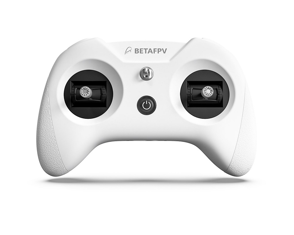
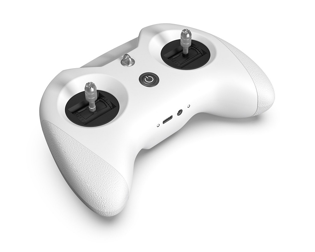
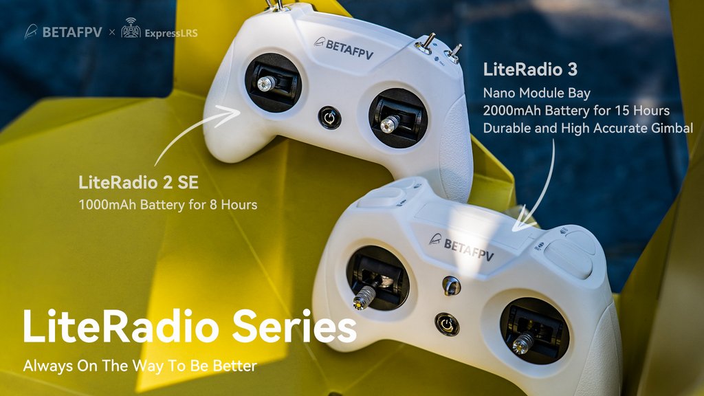
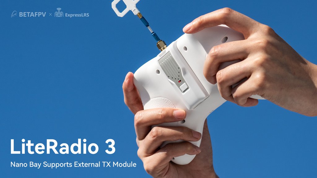
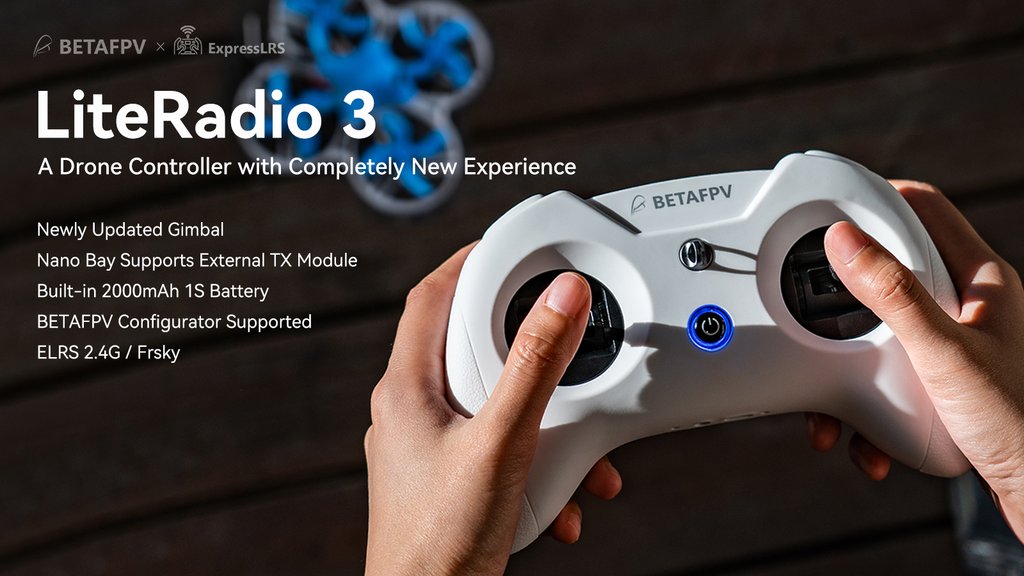
In comparison with LiteRadio 2 SE, the LiteRadio 3 is equipped with a 2000mAh 1S battery, allowing up to 15 working hours (without an external module). A Nano (JR lite) bay on the backside of the radio supports an external module (like?ELRS Nano TX Module) with CRSF protocol. Also LiteRadio 3?gimbal?is newly updated with an accurate potentiometer and adjustable stick ends.
| Comparison table | LiteRadio 3 Transmitter | LiteRadio 2 SE Transmitter |
| Built-in Battery | 2000mAh 1S Battery | 1000mAh 1S Battery |
| Gimbal | Newest durable and accurate?gimbal | Orders from?Dec. are the same as LiteRadio3 |
| Lanyard Hook | Support | Not Support |
| BETAFPV Configurator | Support | Orders from Dec. support |
| Nano Bay for External Module | Support | Not Support |
BetaFPV LiteRadio 3 has Nano (JR Lite) external module bay. You can install the external?ELRS (or maybe Crossfire?) TX module in it. Radio uses only CRSF protocol to communicate with the external module.
Available @
BetaFPV:?https://betafpv.com/products/literadio-3-radio-transmitter
LiteRadio 3 Radio Transmitter User Manual:?https://support.betafpv.com/hc/en-us/articles/4412082282009-Manual-for-LiteRadio-3
Specifications:
Item: LiteRadio 3 Radio Transmitter
Frequency: 2.4GHz
2.4GHz System: CC2500/SX1280
Channel: 8
Support Protocol: Futaba S-FHSS/Frsky FCC D16/Frsky LBT D16/Frsky D8, ExpressLRS 2.4G
Power: ELRS version 25mW/50mW/100mW, Frsky version 100mW
Adapted Drone Type: Multirotor, Airplane
Support USB Charging / Firmware Update
Support BETAFPV Configurator / Most Practice Simulator
LED Light: Green-Power On / Red-Warning if the voltage is lower than 3.5V / Blue-Normal
Battery: Built-in 2000mAh 1S Battery
Charging Connector: USB?Type-C
Recommend External TX Module: ELRS Nano TX Module
Recommend Accessories: Nano Gimbal for LiteRadio 3, Storage Case, Transmitter Neck Strap

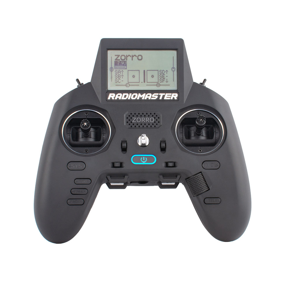
Radiomaster Zorro features and highlights
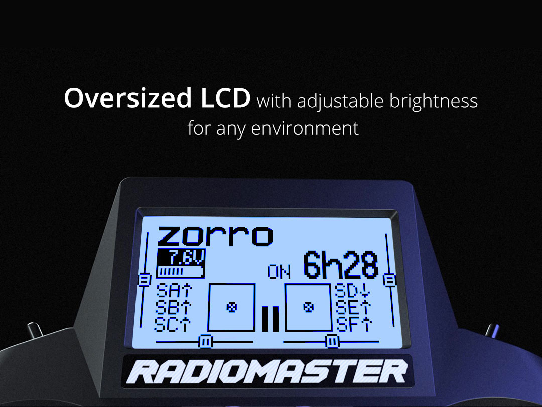
Zorro radio will be equipped with large?128*64?monochrome LCD screen with adjustable brightness.
Radio will have adjustable hall gimbals with stick travel adjustments and the roller wheel for easy navigation.
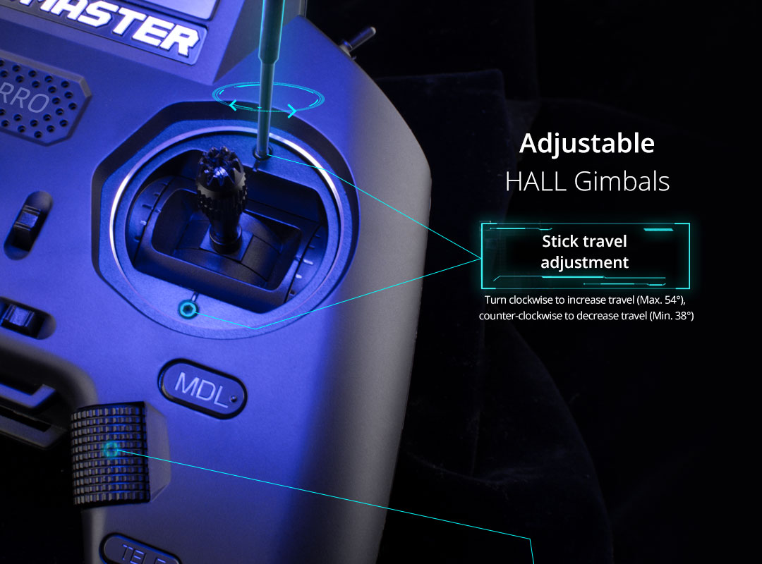
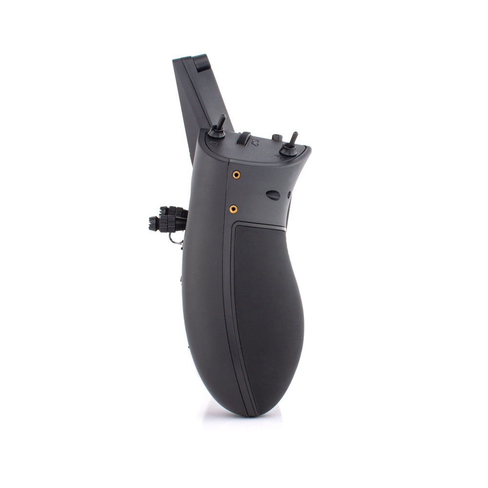
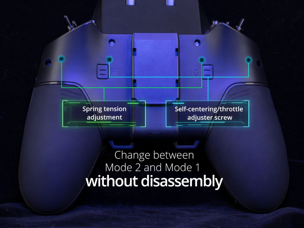
Spring tension and centering/throttle adjustments can be done by by turning the screws and without the need of disassemble the radio.
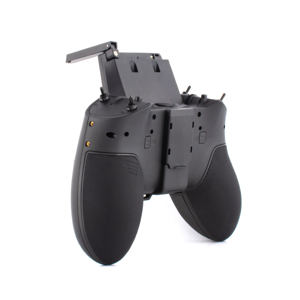
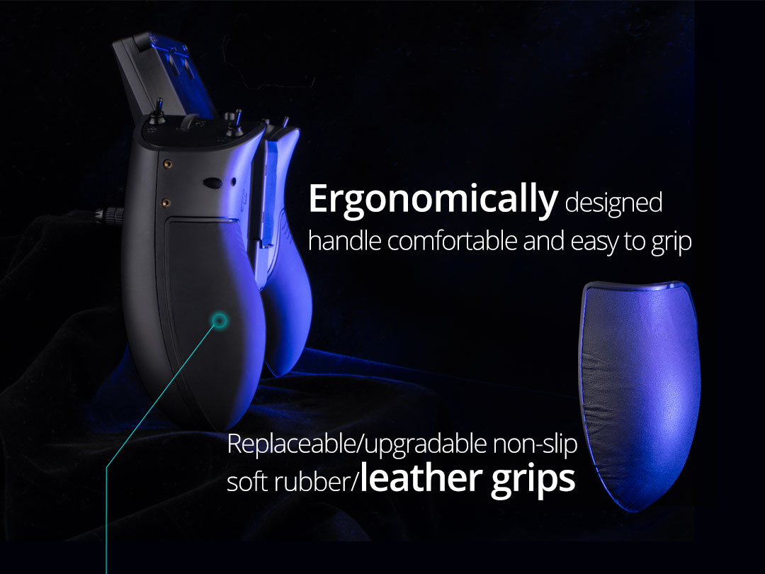
Replaceable soft rubber handle grips and even optional leather grips.
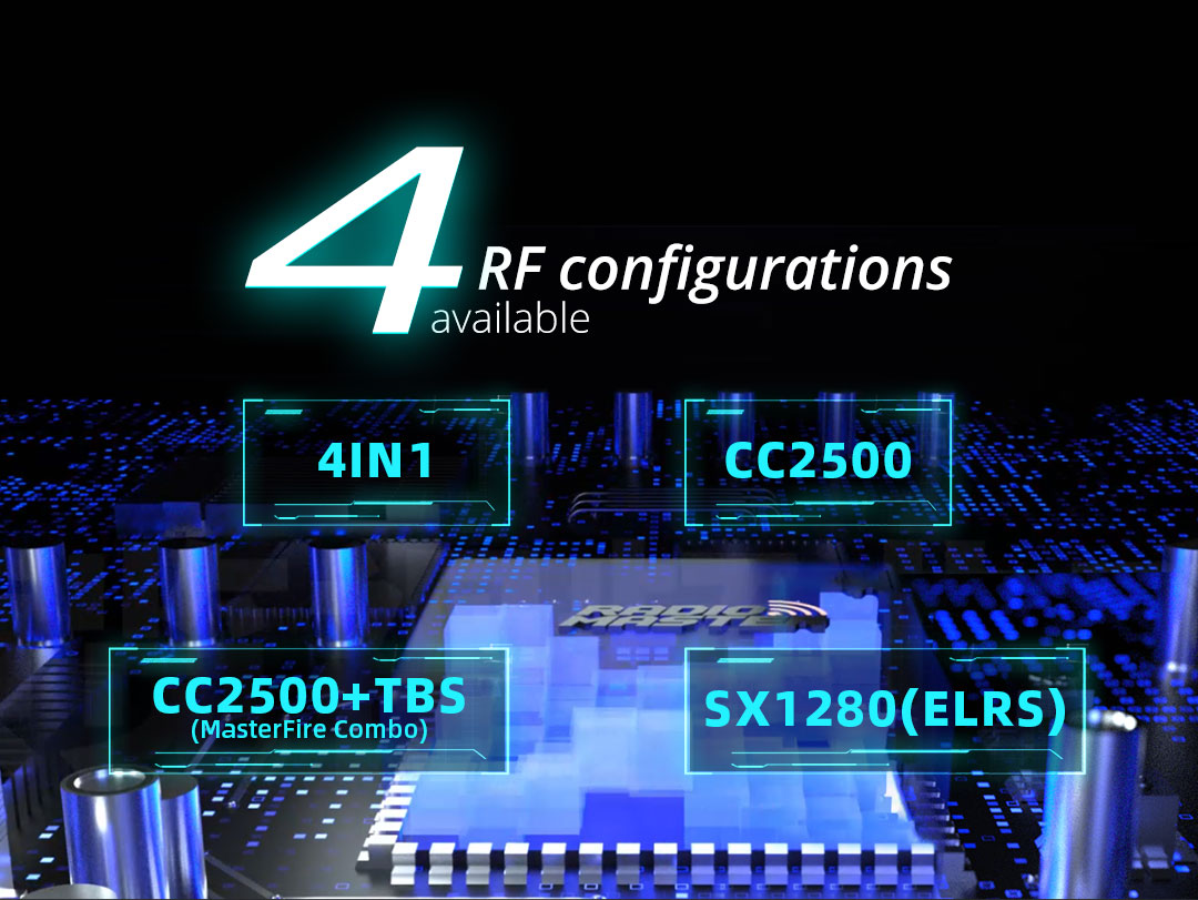
Radiomaster Zorro can be ordered in 4 RF configurations: internal CC2500 (only FrSky and Futaba), internal 4in1 (full multiprotocol), internal ELRS (2.4 GHz) and internal CC2500 plus external TBS Crossfire Nano?TX module.
Radio is powered by two Lion 18350 size batteries.
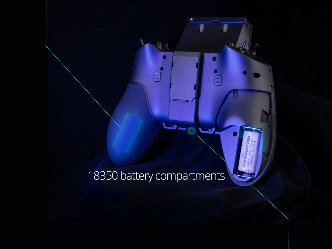
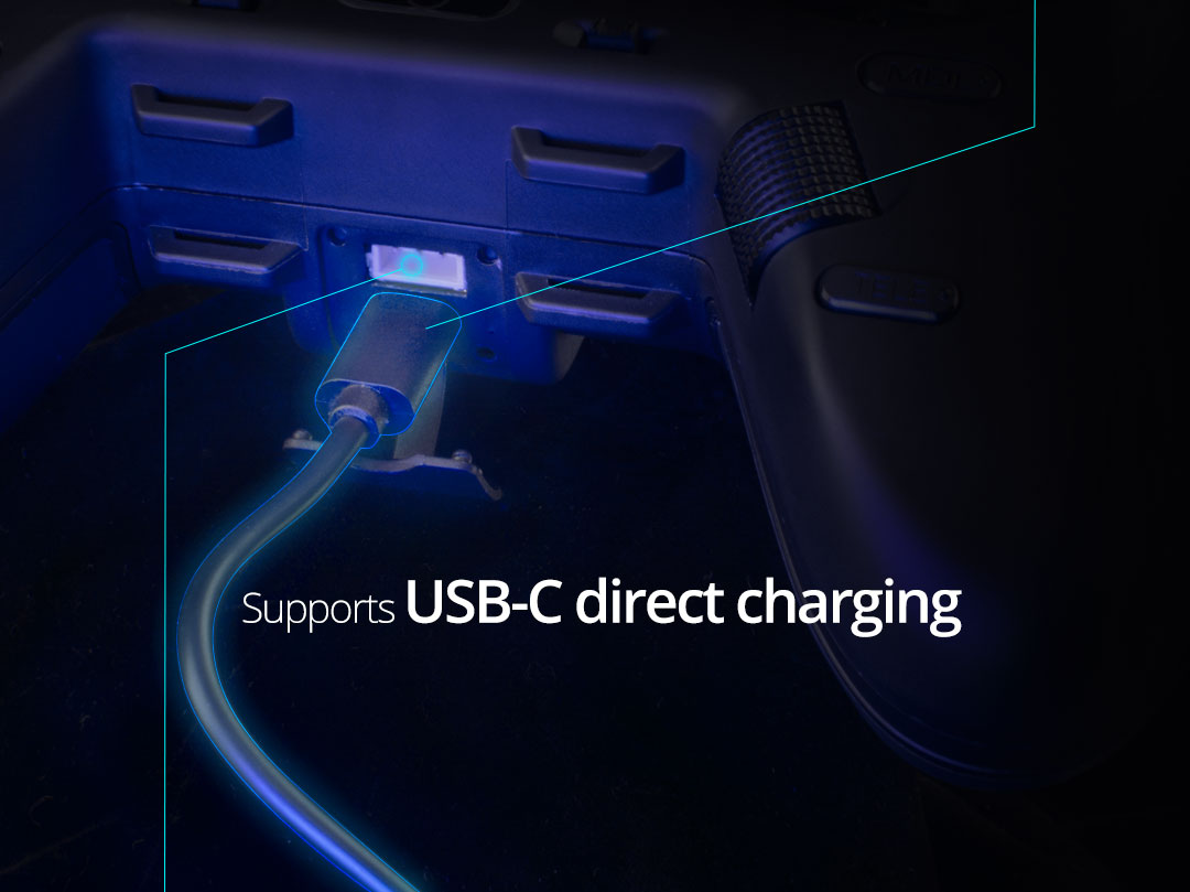
Batteries can be charged by internal charging using USB-C cable.
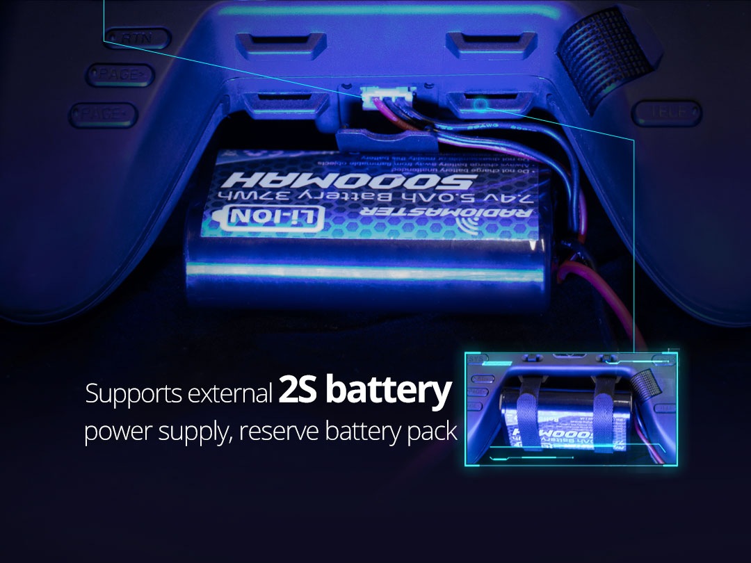
Alternatively radio can be powered by external 2S battery.
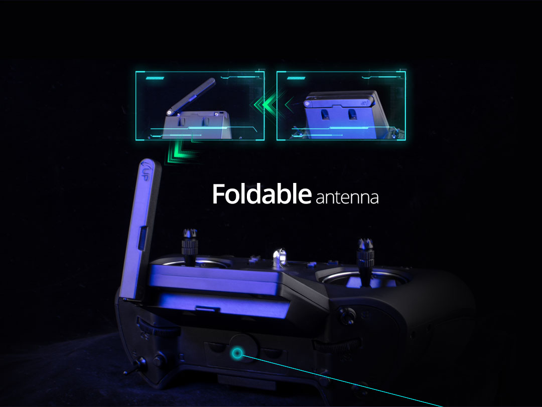
Radio even has foldable antenna.
There are 6 DIY attachement point for various addons (like FPV Screen). Also two user buttons can be found on the back of the radio.
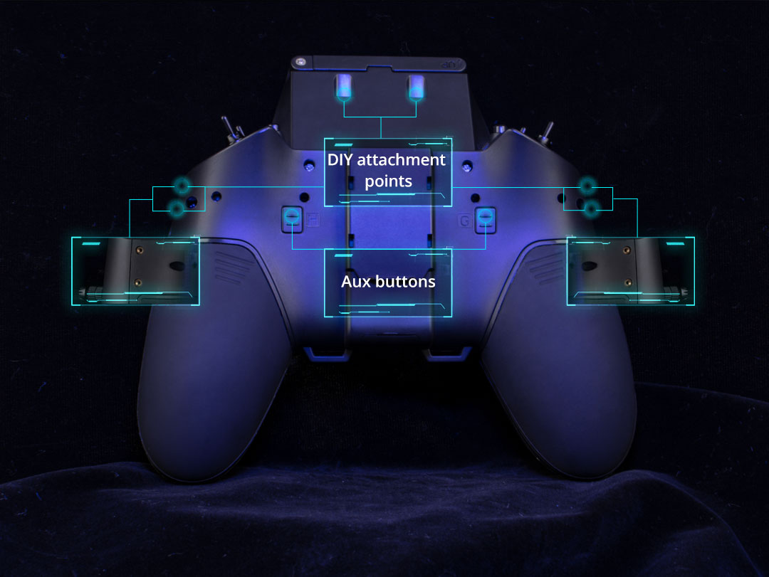
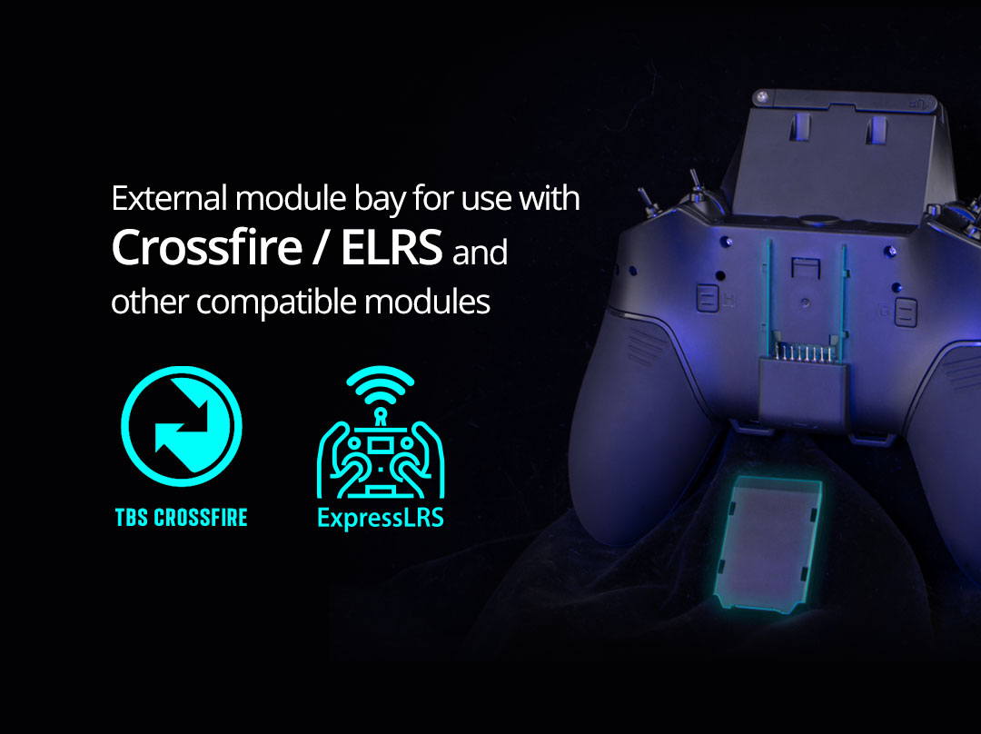
There is external module bay for nano size TX modules.
Radiomaster Zorro is the first of the many radios to come with the internal ELRS module and full featured firmware (such as OpenTX or EdgeTX).
Advertising video from Radiomaster:
Release date: end on January, 2022
Available @
Makerfire (pre-order):?https://shop.makerfire.com/products/radiomaster-zorro-radio-control-cc2500-4in1-elrs-version
Specifications:
Operating frequency: 2.400GHz-2.480GHz
Internal RF Options: 4-in-1 multi-protocol/ ELRS 2.4 GHz
Supported protocols: Module dependent
RF power: CC2500: 20dBm max / 4-in-1: 20dBm max / ELRS: unknown
Antenna: Folding, gain 2db
Operational current: 160mA@8.4V
Operational voltage: 6.6-8.4v DC
Control distance: > 2km @ 20dbm?
Operating system: OpenTX / EdgeTX Compatible
Control channels: Maximum 16 (Rx dependent)
Display: 128*64 Monochrome LCD
Battery: 2 x 18350 (Not included)
Charging: Built in USB-C Charging
Gimbals: Hall-effect
Module bay: Nano size (Compatible with TBS Nano Crossfire / Nano Tracer / IRC Ghost)
Firmware Upgrade method: Via USB or SD card (SD Not included)
Physical dimensions: 170*159*108mm
Weight: 350 grams
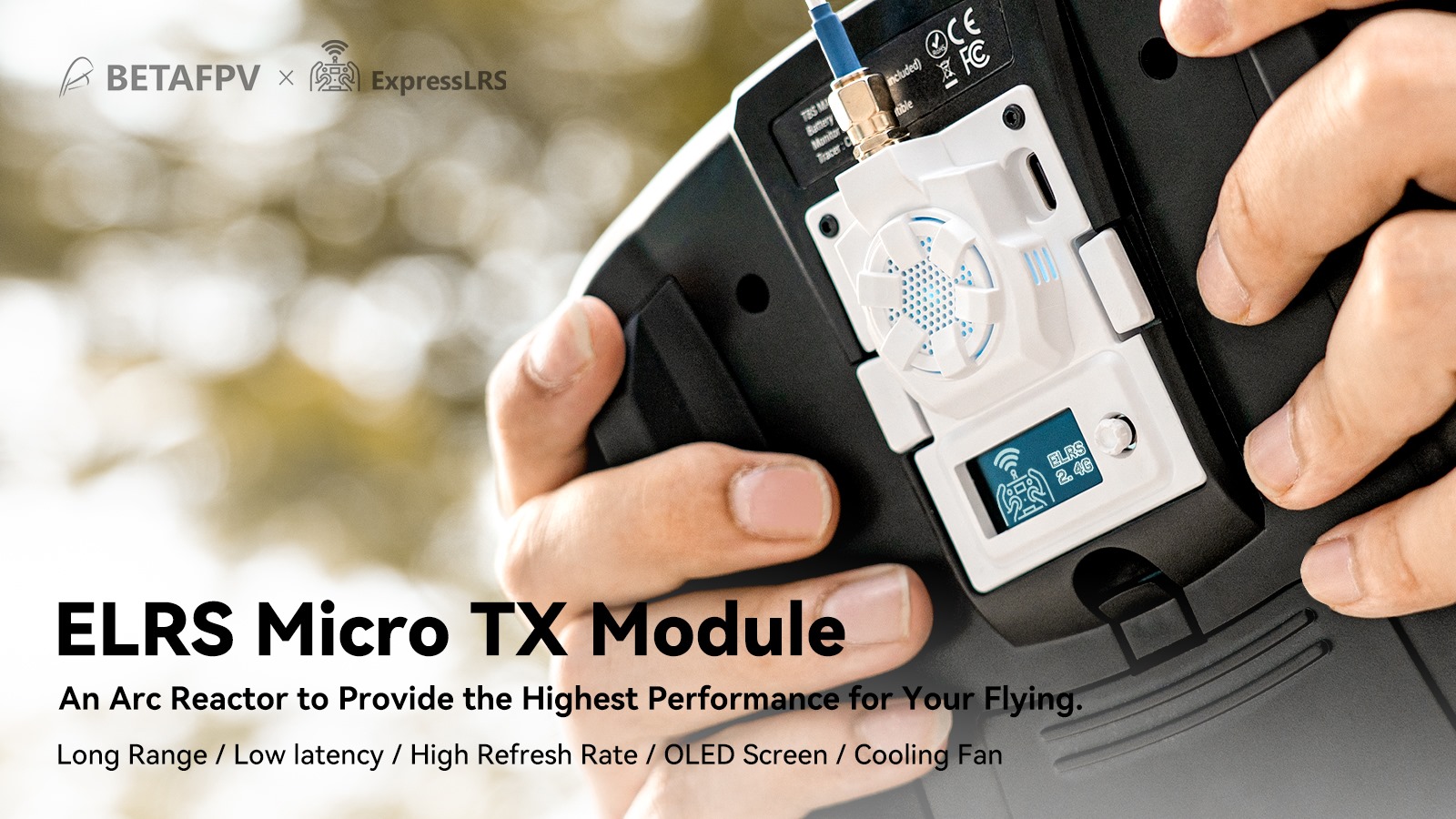
BetaFPV ELRS Micro TX module has output power up to 500mW.??OLED screen and navigation button makes possible to change the ExpressLRS settings without the OpenTX Lua script, enabling the support for the radios that don’t run on OpenTX firmware (Futaba, Radiolink, etc).
There is USB Type-C connector for firmware updates and XT30 connector for external power support.
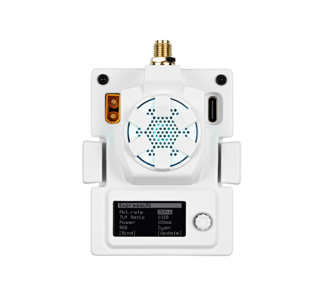
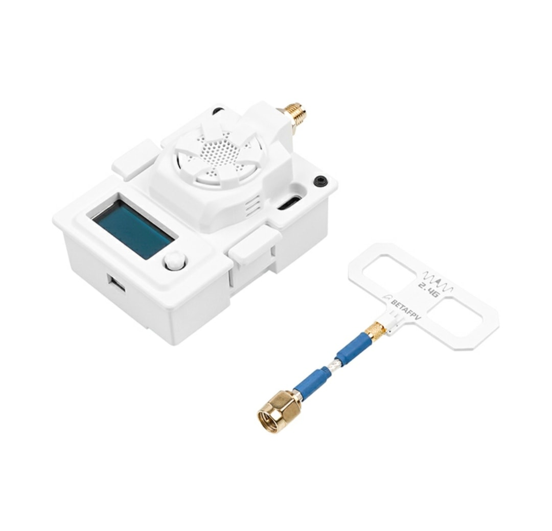
BetaFPV ELRS Micro TX module has cooling fan that turns on automatically according to the output power level (start from 250mW) and? multicolor LED light to ad fancy lighting for on your module.
Oh, and BetaFPV states that this module has “An Arc Reactor to provide the highest performance…”?
Available in 2.4GHz, 868MHz and 915MHz options @
BetaFPV:?https://betafpv.com/products/elrs-micro-tx-module
Specifications
Packet refresh rate: 25Hz/50Hz/100Hz/200Hz (915MHz/868MHz), 50Hz/150Hz/250Hz/500Hz (2.4GHz)
RF output power: 25mW/50mW/100mW/250mW/500mW (2.4GHz), 100mW/250mW/500mW (915MHz/868MHz)
Frequency bands (Micro RF Module 2.4G version): 2.4GHz ISM
Frequency bands (Micro RF Module 915MHz/868MHz version): 915MHz FCC/868MHz EU
Input voltage: 5V~12V
XT30 port: 5V~12V, recommend 2S(8.4V) battery, DO NOT support 3S(12.6V) or above
USB port: Type-C